Advertisement
FAB205-6P5 Series Quick Installation Guide
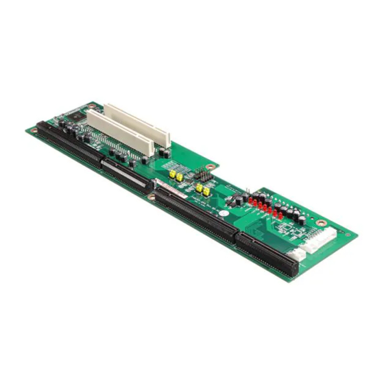
III.
Board Dimensions
Top Side
Bottom Side
4
©
Copyright 2008 AXIOMTEK Co., Ltd.
Version A1 April 2008
Printed in Taiwan
9419B205020E
FAB205-6P5 Series Quick Installation Guide
I.
Checklist
FAB205-6P5 6 Slot PICMG 1.3 Bus
Butterfly Backplane x 1
Note: Please contact your local vendors if any damaged or missing items.
DO NOT apply power to the board if any damaged components.
II.
Connectors
Connector
SHB1 ~ SHB4
PICMG 1.3 Full-sized SBC Slot
SPCI1~SPCI3, PCI4
PCI Slots 32-bit/33MHz
PCI5
PCI Slot through PCIe*1 to PCI bridge
SCN2
24-Pin ATX Power Connector
CN3
8-Pin Power Output Connector
PWR_BT1
Power ON/OFF push button Connector
HW_RST1
Hardware Reset Connector
8-Pin Power Output Connector (CN3)
Pin
1
2
3
4
5
6
7
8
©
Copyright 2008 AXIOMTEK Co., Ltd.
Version A1 April 2008
Printed in Taiwan
9419B205020E
Quick Installation Guide x 1
Description
Signal
GND
GND
5VSB
+3.3V
-5v
+5V
-12V
+12V
1
Advertisement
Table of Contents

Related Manuals for AXIOMTEK FAB205-6P5 Series


Summary of Contents for AXIOMTEK FAB205-6P5 Series
- Page 1 FAB205-6P5 Series Quick Installation Guide FAB205-6P5 Series Quick Installation Guide III. Board Dimensions Checklist FAB205-6P5 6 Slot PICMG 1.3 Bus Quick Installation Guide x 1 Butterfly Backplane x 1 Note: Please contact your local vendors if any damaged or missing items.
- Page 2 FAB205-6P5 Series Quick Installation Guide FAB205-6P5 Series Quick Installation Guide Power ON/OFF Push Button Connector (PWR_BT1) 24-Pin ATX Power Connector (CN2) Cable Cable Signal Signal Color Color 3.3V Brown 3.3V Brown 3.3V Brown -12V Blue Black Black Signal PS_ON Green...
Need help?
Do you have a question about the FAB205-6P5 Series and is the answer not in the manual?
Questions and answers