Table of Contents
Advertisement
Available languages
Available languages
Quick Links
GF Piping Systems
Electric Actuators
Type EA04
Operating Instructions
Elektrische Stellantriebe
Typ EA04
Betriebsanleitung
Servomécanisme électrique
Types EA04
Manuel d'utilisation
Servomecanismo eléctrico
Tipos EA04
Manual de instrucciones
700278081 Electric Actuators Type EA04
6329 / DE EN FR ES / 02 (10.2022)
© Georg Fischer Piping Systems Ltd
CH-8201 Schaffhausen/Switzerland
+41 52 631 30 26/info.ps@georgfischer.com
www.gfps.com
Advertisement
Chapters
Table of Contents

Related Manuals for GF EA04


Summary of Contents for GF EA04
- Page 1 Servomécanisme électrique Types EA04 Manuel d'utilisation Servomecanismo eléctrico Tipos EA04 Manual de instrucciones 700278081 Electric Actuators Type EA04 6329 / DE EN FR ES / 02 (10.2022) © Georg Fischer Piping Systems Ltd CH-8201 Schaffhausen/Switzerland +41 52 631 30 26/info.ps@georgfischer.com www.gfps.com...
- Page 2 Content Electric Actuators Type EA04 Elektrische Stellantriebe Typ EA04 Servomécanisme électrique Type EA04 Servomecanismo eléctrico Tipo EA04...
- Page 3 GF Piping Systems Electric Actuators Type EA04 Instruction manual...
- Page 4 GF Piping Systems Translation of the original instruction manual Disclaimer The technical data are not binding. They neither constitute expressly warranted characteristics nor guaranteed properties nor a guaran- teed durability. It is subject to modification. Our General Terms of Sale apply.
-
Page 5: Table Of Contents
Design and function Principle of operation Operating mode on standard operation Technical specifications Installation Assembly actuator with ball valve Type 546 Pro Electrical connection Connection diagram Limit switches Commissioning Functional test Using manual emergency override Status light (only EA04 20Nm) - Page 6 Electric Actuators Type EA04 Instruction manual Maintenance Troubleshooting Spare parts Disposal...
-
Page 7: About This Document
GF Planning Fundamentals Industry 700671687 Data sheet www.gfps.com/is-manuals-valves Chemical resistance www.gfps.com Instruction manual ball valve These documents are available from the GF Piping Systems Sales Company or at www.gfps.com. Symbols Symbol Indication Listed in no particular order. • ► Call for action: Here, something has to be done. -
Page 8: Safety Information
Electric Actuators Type EA04 Instruction manual Safety Information The safety instructions apply to use as described under „Intended use“. The safety instructions do not cover the following cases: Incidental events occurring during installation, operation and service. • The operator is responsible for the local and site-related safety regulations. -
Page 9: Notes For Service And Operating Personnel
Instruction manual Electric Actuators Type EA04 Notes for service and operating personnel The following target groups are addressed in these operating instructions: Operators Operators are instructed in the operation of the product and observe the safety guidelines. Service personnel The service personnel has professional technical training and performs installation, putting into operation, as well as maintenance work. -
Page 10: Product Description
Product description Intended use The EA04 electric actuators are designed for mounting on a valve and for connection to a control system provided by the plant and are intended to operate valves with swivel movements of up to 180°. The product is not intended for any other type of use than those listed here. Failure to observe the instructions contained in this manual will void the manufacturer›s liability for the above-mentioned products. -
Page 11: Type Overview
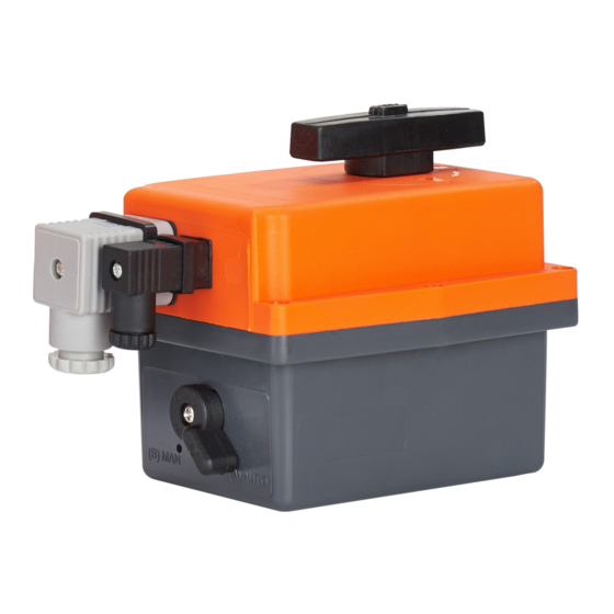
Internal assembly number Maximum torque Voltage type Regulating time Duty cycle Serial number CE marking 3.5.2 Design EA04 Pos. Designation Switch manual emergency override Position indicator / manual emergency override Connection for control voltage Connection for feedback Status light (only EA04 20Nm) -
Page 12: Principle Of Operation
The position indicator shows the valve position. The valve positions can be read on the installed cover. NOTE! GF actuators are always delivered in the OPEN position. When the cover is installed, the following image can be seen (Example ball valve):... -
Page 13: Operating Mode On Standard Operation
Instruction manual Electric Actuators Type EA04 Operating mode on standard operation The actuator runs by connecting the mains voltage from the „Open“ position to the „Closed“ position. By switching the mains voltage to the other input, the actuator runs from the „Closed“ position to the „Open“... - Page 14 Electric Actuators Type EA04 Instruction manual 3.8.3 Dimensions EA04 20Nm...
-
Page 15: Installation
Instruction manual Electric Actuators Type EA04 Installation Assembly actuator with ball valve Type 546 Pro The electrical actuator can built on the ball valve type 546 Pro with the appropriate coupling piece and appropriate adapter: Overveiw Description Insert the two screws (1) into the hexagonal attachments in the adapter panel (2). -
Page 16: Electrical Connection
Electric Actuators Type EA04 Instruction manual ► In addition to these instruction manual, also follow manufacturer›s specifications on ball valve type 546 Pro. ► Before installation, compare technical data of the actuator with the control and the valve. Only install actuator if the data match- ►... -
Page 17: Connection Diagram
Instruction manual Electric Actuators Type EA04 Connection diagram The power supply is connected with the large, grey DIN plug. NEUTRAL o (-) PHASE o (+) ACTUATING MOVEMENT PIN 1 PIN 2 CLOSED PIN 1 PIN 3 OPEN PIN 4 IS THE CONNECTION TO EARTH OR GROUND The potential-free connection is made via the small, black DIN plug. -
Page 18: Commissioning
Electric Actuators Type EA04 Instruction manual Commissioning Before commissioning the system, carry out a functional test of the product. Functional test Before actuator is connected to mains voltage: ► Make sure that main voltage matches details on type lable. ► Make sure that actuator is connected properly. -
Page 19: Using Manual Emergency Override
Instruction manual Electric Actuators Type EA04 Using manual emergency override The integrated manual emergency override is used to move the actuator manually into another position. The integrated manual emergency override allows the actuator to continue operating temporarily if there is no power. -
Page 20: Status Light (Only Ea04 20Nm)
Maintenance CAUTION! Lack of product quality through use of spare parts not provided by GF Piping Systems! Danger of injury. ► Only use the listed spare parts, see Chapter “Spare parts list”. ► Set maintenance intervals as per the conditions of use (e. g. actuating cycles, fluid, ambient temperature). - Page 21 ► Replace valve stem Valve stem twisted Spare parts Designation Code No. Actuator EA04 10 Nm 100–230 V AC/DC 198 151 480 Actuator EA04 10 Nm 24 AC/DC 198 151 481 Actuator EA04 20 Nm 100-230 V AC/DC 198 151 482...
- Page 22 Electric Actuators Type EA04 Instruction manual Disposal Before disposing of the different material, separate it by recyclables, normal waste and special waste. Comply with local legal regulations and provisions when recycling or disposing of the product, the individual components and the packaging.
- Page 23 Instruction manual Electric Actuators Type EA04...
- Page 24 GF Piping Systems Local support around the world Visit our webpage to get in touch with your local specialist: www.gfps.com/our-locations The information and technical data (altogether “Data”) herein are not binding, unless explicitly confirmed in writing. The Data neither constitutes any expressed, implied or warranted characteristics, nor guaranteed properties or a guaranteed...
- Page 25 GF Piping Systems Elektrische Stellantriebe Typ EA04 Betriebsanleitung...
- Page 26 GF Piping Systems Originalbetriebsanleitung Haftungsausschluss Die technischen Daten sind unverbindlich. Sie gelten nicht als zugesicherte Eigenschaften oder als Beschaffenheits- oder Haltbarkeits- garantien. Änderungen vorbehalten. Es gelten unsere Allgemeinen Verkaufsbedingungen.
- Page 27 Betriebsanleitung Elektrische Stellantriebe Typ EA04 Inhaltsverzeichnis Zu diesem Dokument Mitgeltende Dokumente Symbole Abkürzungen Sicherheitshinweise Bedeutung der Signalwörter Betriebsanleitung beachten Sicherheit und Verantwortung Hinweise für Service- und Bedienpersonal Produktbeschreibung Bestimmungsgemässe Verwendung Nicht bestimmungsgemässe Verwendung EG-Einbauerklärung Typenübersicht Aufbau und Funktion Funktionsweise Funktionsweise bei Standardbetrieb...
- Page 28 Elektrische Stellantriebe Typ EA04 Betriebsanleitung Wartung Störungsbehebung Ersatzteile Entsorgung...
-
Page 29: Zu Diesem Dokument
Betriebsanleitung Elektrische Stellantriebe Typ EA04 Zu diesem Dokument Mitgeltende Dokumente Dokument GF Planungsgrundlagen Industrie 700671686 Datenblatt www.gfps.com/is-manuals-valves Chemische Beständigkeit www.gfps.com Betriebsanleitung Kugelhahn Diese Unterlagen sind über die Georg Fischer Vertriebsgesellschaft oder unter www.gfps.com erhältlich. Symbole Symbol Bedeutung Aufzählung in nicht definierter Reihenfolge. -
Page 30: Sicherheitshinweise
Elektrische Stellantriebe Typ EA04 Betriebsanleitung Sicherheitshinweise Die Sicherheitshinweise gelten für den Einsatz wie beschrieben unter „Bestimmungsgemässe Verwendung“. Die Sicherheitshinweise decken folgende Fälle nicht ab: Bei Installation, Betrieb und Wartung zufällig auftretende Ereignisse. • Für die lokalen und ortsbezogenen Sicherheitsbestimmmungen ist der Betreiber verantwortlich. -
Page 31: Hinweise Für Service- Und Bedienpersonal
Betriebsanleitung Elektrische Stellantriebe Typ EA04 Hinweise für Service- und Bedienpersonal Folgende Zielgruppen werden in dieser Betriebsanleitung angesprochen: Bediener Bediener sind in die Bedienung des Produktes eingewiesen und befolgen die Sicherheitsvorschriften. Servicepersonal Das Servicepersonal verfügt über eine fachtechnische Ausbildung und führt die Installation, Inbetriebnahme, sowie Wartungsarbei- ten durch. -
Page 32: Produktbeschreibung
Produktbeschreibung Bestimmungsgemässe Verwendung Die elektrischen Stellantriebe EA04 sind zum Aufbau auf ein Ventil und zum Anschluss an eine anlagenseitig beigestellte Steuerung vorgesehenund dazu bestimmt, Kugelhähne mit Schwenkbewegungen bis 180° zu betätigen. Für andere als die hier aufgeführten Verwendungsarten ist das Produkt nicht vorgesehen. Bei Nichtbeachten der in dieser Anleitung enthaltenen Hinweise erlischt die Haftung des Herstellers für die oben genannten Produkte. -
Page 33: Typenübersicht
Betriebsanleitung Elektrische Stellantriebe Typ EA04 Typenübersicht Standard Typ Spannung Drehmoment Code Elektrischer Anschluss EA04 100 – 230V 10 Nm 198 151 480 DIN-Stecker EA04 10 Nm 198 151 481 DIN-Stecker EA04 24 – 240V 20 Nm 198 151 492 DIN-Stecker Aufbau und Funktion 3.5.1... -
Page 34: Funktionsweise
3.6.1 Stellungsanzeige Die Stellungsanzeige zeigt die Ventilposition an. Die Ventilposition kann am montierten Deckel abgelesen werden. HINWEIS! GF Stellantriebe werden immer in der AUF Position ausgeliefert. Bei montiertem Deckel ist folgendes Bild zu sehen (Beispiel: Kugelhahn): Stellungsanzeige Funktion Ventil Stellwinkel 0°... -
Page 35: Funktionsweise Bei Standardbetrieb
Betriebsanleitung Elektrische Stellantriebe Typ EA04 Funktionsweise bei Standardbetrieb Der Antrieb fährt durch Anlegen der Netzspannung von der „Auf“-Position in die „Zu“-Position. Durch Umschalten der Netzspannung auf den anderen Eingang fährt der Antrieb von der „Zu“-Position in die „Auf“- Position. Die Endlagen werden durch zwei Endschalter definiert. - Page 36 Elektrische Stellantriebe Typ EA04 Betriebsanleitung 3.8.3 Abmessungen EA04 20Nm...
-
Page 37: Installation
Betriebsanleitung Elektrische Stellantriebe Typ EA04 Installation Montage Antrieb mit Kugelhahn Typ 546 Pro Der elektrische Antrieb kann mit geeignetem Kupplungsstück und geeignetem Adapter auf den Kugelhahn Typ 546 Pro aufgebaut werden: Übersicht Beschreibung Die zwei Schrauben (1) in die Sechskant-Aufnahmen der Adapterplatte (2) stecken. -
Page 38: Elektrischer Anschluss
Elektrische Stellantriebe Typ EA04 Betriebsanleitung ► Zusätzlich zu dieser Betriebsanleitung auch die Herstellervorgaben zum Kugelhahn Typ 546 Pro beachten. ► Vor Installation technische Daten des Antriebs mit der Steuerung und der Armatur vergleichen. Stellantrieb nur installieren, wenn die Daten zueinan¬der passen. -
Page 39: Anschlussschema
Betriebsanleitung Elektrische Stellantriebe Typ EA04 Anschlussschema Die Spannungsversorung wird mit dem grossen, grauen DIN-Stecker verbunden. NEUTRAL o (-) PHASE o (+) STELLBEWE- GUNG PIN 1 PIN 2 PIN 1 PIN 3 PIN 4 IST DER ANSCHLUSS AN ERDE ODER MASSE Der potentialfreie Anschluss erfolgt über den kleinen, schwarzen DIN-Stecker. -
Page 40: Inbetriebnahme
Elektrische Stellantriebe Typ EA04 Betriebsanleitung Inbetriebnahme Vor der Inbetriebnahme der Anlage muss eine Funktionsprüfung des Stellantriebs durchgeführt werden. Funktionsprüfung Bevor Stellantrieb mit Netzspannung verbunden wird: ► Sicherstellen, dass Netzspannung mit Angaben auf Typenschild übereinstimmt ► Sicherstellen, dass Antrieb korrekt angeschlossen ist ►... -
Page 41: Handnotbetätigung Einsetzen
Betriebsanleitung Elektrische Stellantriebe Typ EA04 Handnotbetätigung einsetzen Die integrierte Handnotbetätigung dient dazu, den Stellantrieb manuell in eine andere Position zu fahren. Die integrierte Handnot- betätigung ermöglicht den Betrieb des Antriebs kurzfristig aufrechtzuerhalten, wenn kein Strom anliegt. ► Wenn der Stellantrieb dauerhaft oder häufiger ausfällt: Antrieb austauschen. -
Page 42: Statusleuchte (Nur Ea04 20Nm)
Wartung VORSICHT! Fehlende Produktqualität durch Verwendung von Ersatzteilen, die nicht von GF Piping Systems zur Verfügung gestellt wurden! Verletzungsgefahr. ► Ausschliesslich die aufgeführten Ersatzteile verwenden, siehe Kapitel „Ersatzteilliste“. ► Wartungsintervalle entsprechend der Einsatzbedingungen festlegen (z. B. Stellzyklen, Medium, Umgebungstemperatur). - Page 43 ► Ventilzapfen austauschen Ventilzapfen verdreht Ersatzteile Bezeichnung Code-Nr. Antrieb EA04 10 Nm 100–230 V AC/DC 198 151 480 Antrieb EA04 10 Nm 24 AC/DC 198 151 481 Antrieb EA04 20 Nm 100-230 V AC/DC 198 151 482 Antrieb EA04 20 Nm 24 AC/DC...
- Page 44 Elektrische Stellantriebe Typ EA04 Betriebsanleitung Entsorgung WARNUNG! Teile des Produkts können mit gesundheits- und umweltschädlichen Medien kontaminiert sein, so dass eine einfache Reinigung nicht ausreichend ist! Gefahr von Personen- oder Umweltschäden durch diese Medien. ► Vor der Entsorgung des Produkts: auslaufende Medien sammeln und entsprechend der örtlichen Vorschriften entsorgen.
- Page 45 Betriebsanleitung Elektrische Stellantriebe Typ EA04...
- Page 46 GF Piping Systems Lokale Unterstützung – weltweit Besuchen Sie unsere Website und kontaktieren Sie Ihren lokalen Spezialisten: www.gfps.com/our-locations Die hierin enthaltenen Informationen und technischen Daten (insgesamt „Daten”) sind nicht verbindlich, sofern sie nicht ausdrücklich schriftlich bestätigt werden. Die Daten begründen weder ausdrückliche, stillschweigende oder zugesicherte Merkmale noch garantierte Eigenschaften oder eine...
- Page 47 GF Piping Systems Servomécanisme électrique Type EA04 Mode d‘emploi...
- Page 48 GF Piping Systems Traduction du manuel d‘utilisation original Exclusion de responsabilité Les données techniques ne sont pas contractuelles. Elles ne sont pas des garanties et ne constituent pas non plus un gage de propriété intrinsèque ou de durabilité. Sous réserve de modifications. Nos conditions générales de vente s’appliquent.
- Page 49 Données techniques Installation Montage servomécanisme avec vanne à bille 546 Pro Raccordement électrique Schéma de raccordement Interrupteurs de fin de course Mise en service Contrôle de fonctionnement Utilisation de la commande manuelle de secours Voyant d'état (uniquement EA04 20 Nm)
- Page 50 Servomécanisme électrique Type EA04 Mode d‘emploi Maintenance Dépannage Pièces de rechange Mise au rebut...
-
Page 51: À Propos De Ce Document
Mode d‘emploi Servomécanisme électrique Type EA04 À propos de ce document Documents applicables Document Bases de planification GF pour l'industrie 700671687 Fiche technique www.gfps.com/is-manuals-valves Résistance chimique www.gfps.com Mode d‘emploi du robinet à bille Ces documents sont disponibles auprès de la société de vente de Georg Fischer ou sur le site www.gfps.com. -
Page 52: Consignes De Sécurité
Servomécanisme électrique Type EA04 Mode d‘emploi Consignes de sécurité Les consignes de sécurité se fondent sur un emploi comme décrit au chapitre « Utilisation conforme aux dispositions ». Les consignes de sécurité ne couvrent pas les cas suivants : Événements fortuits survenant pendant l‘installation, le fonctionnement et la maintenance. -
Page 53: Consignes Pour Le Personnel D'entretien Et Les Opérateurs
Mode d‘emploi Servomécanisme électrique Type EA04 Consignes pour le personnel d‘entretien et les opérateurs Ce manuel d‘utilisation s‘adresse aux groupes cibles suivants : Opérateurs Opérateur : les opérateurs sont formés à l‘utilisation du produit et suivent les prescriptions de sécurité. Personnel d‘entretien Personnel d‘entretien : le personnel d‘entretien dispose d‘une formation technique spécialisée et procède aux travaux d‘installation,... -
Page 54: Description Du Produit
Utilisation conforme aux dispositions Les servomécanismes électriques EA04 sont conçus pour être montés sur une vanne et pour être raccordés à un système de régu- lation fourni par l’usine. Ils sont destinés à actionner des vannes à bille avec des mouvements de pivotement jusqu’à 180°. -
Page 55: Variantes Et Types De Produits Décrits
Numéro de série Marquage CE 3.5.2 Structure EA04 N° Désignation Interrupteur de la commande manuelle de secours Indicateur de position / commande manuelle de secours Raccord pour la tension de commande Raccord pour retour d'information Voyant d'état (uniquement EA04 20 Nm) -
Page 56: Fonctionnement
L‘indicateur de position indique la position de la vanne. Les positions de la vanne peuvent être relevées lorsque le couvercle est monté. REMARQUE ! Les servomécanismes GF sont toujours livrés en position « OUVERTS ». Lorsque le couvercle est monté, le schéma suivant est visible (exemple : vanne à bille) : OUVERTS FERMÉ... -
Page 57: Mode De Fonctionnement En Mode Standard
Mode d‘emploi Servomécanisme électrique Type EA04 Mode de fonctionnement en mode standard Avec l‘application de la tension, le servomécanisme passe de la position « ouvert » à la position « fermé ». En commutant la ten- sion secteur sur une autre entrée, le servomécanisme passe de la position « fermé » à la position « ouvert ». - Page 58 Servomécanisme électrique Type EA04 Mode d‘emploi 3.8.3 Dimensions EA04 20Nm...
-
Page 59: Installation
Mode d‘emploi Servomécanisme électrique Type EA04 Installation Montage servomécanisme avec vanne à bille 546 Pro Le servomécanisme électrique peut être monté sur les vannes à bille de type 546 Pro avec une pièce d‘accouplement adaptée : Aperçu Description Enficher les deux vis (1) dans les logements hexagonaux de la plaque d‘adaptation (2). -
Page 60: Raccordement Électrique
Servomécanisme électrique Type EA04 Mode d‘emploi ► Outre le présent mode d'emploi, respecter également les prescriptions du fabricant du robinet à bille type 546 Pro. ► Avant l'installation, comparer les caractéristiques techniques du servomécanisme avec celles de commande et de la vanne. -
Page 61: Schéma De Raccordement
Mode d‘emploi Servomécanisme électrique Type EA04 Schéma de raccordement L‘alimentation en tension est raccordée avec la grande fiche DIN grise. NEUTREo (-) PHASE o (+) MOUVEMENT DE RÉGLAGE BROCHE 1 BROCHE 2 FERMÉ BROCHE 1 BROCHE 3 FERMÉ BROCHE 4 : RACCORD A LA TERRE OU A LA MASSE Le raccordement libre de potentiel se fait via la petite fiche DIN noire. -
Page 62: Mise En Service
Servomécanisme électrique Type EA04 Mode d‘emploi Mise en service Avant la mise en service de l‘installation, vérifier le fonctionnement du produit. Contrôle de fonctionnement Avant de connecter le servomécanisme à la tension secteur : ► S'assurer que la tension secteur correspond aux indications de la plaque signalétique. -
Page 63: Utilisation De La Commande Manuelle De Secours
Mode d‘emploi Servomécanisme électrique Type EA04 Utilisation de la commande manuelle de secours La commande manuelle de secours intégré permet de placer manuellement le servomécanisme dans une autre position. La com- mande manuelle de secours intégré permet de maintenir temporairement le fonctionnement du servomécanisme en cas de coupure de courant. -
Page 64: Voyant D'état (Uniquement Ea04 20 Nm)
Maintenance CAUTION! Qualité de produit défaillante due à l‘utilisation de pièces de rechange non fournies par GF Piping Systems ! Risque de blessure. ► Utiliser exclusivement les pièces de rechange indiquées dans le chapitre « Liste de pièces de rechange ». - Page 65 ► Remplacer le pointeau de vanne Pointeau de vanne inversé Pièces de rechange Désignation Code Servomécanisme EA04 10 Nm 100–230 V CA/CC 198 151 480 Servomécanisme EA04 10 Nm 24 V CA/CC 198 151 481 Servomécanisme EA04 20 Nm 100-230 V CA/CC 198 151 482 Servomécanisme EA04 20 Nm 24 V CA/CC...
- Page 66 ► Trier les différents matériaux (plastiques, métaux, etc.) et les éliminer conformément aux dispositions locales. Un produit identifié par le symbole suivant doit être éliminé parmi les appareils électriques et électroniques. En cas de questions relatives à l'élimination du produit, contactez la représentation nationale de GF Piping Systems.
- Page 67 Mode d‘emploi Servomécanisme électrique Type EA04...
- Page 68 GF Piping Systems Assistance locale dans le monde entier Rendez-vous sur notre site internet pour contacter votre expert local : www.gfps.com/our-locations Les informations et les données techniques (ci-après « Données ») contenues ici ne sont pas contractuelles, sauf mention explicite par écrit.
- Page 69 GF Piping Systems Servomecanismo eléctrico Tipo EA04 Instrucciones de uso...
- Page 70 GF Piping Systems Traducción del manual de usuario original Exclusión de responsabilidad Los datos técnicos no son vinculantes. No constituyen una garantía de propiedad intrínseca o de durabilidad. Nos reservamos el derecho a realizar cambios. Se aplican nuestras condiciones generales de contratación.
- Page 71 Datos técnicos Instalación Montaje del actuador con válvula esférica 546 Pro Conexión eléctrica Esquema de conexiones Interruptor de fin de carrera Puesta en marcha Prueba de funcionamiento Utilizar el control manual de emergencia Lámpara de estado (sólo EA04 20 Nm)
- Page 72 Servomecanismo eléctrico Tipo EA04 Instrucciones de uso Mantenimiento Solución de problemas Piezas de recambio Eliminación...
-
Page 73: Acerca De Este Documento
Instrucciones de uso Servomecanismo eléctrico Tipo EA04 Acerca de este documento Documentación complementaria Documento Fundamentos de planificación industrial de GF 700671687 Ficha técnica www.gfps.com/is-manuals-valves Resistencia química www.gfps.com Instrucciones de uso de la válvula de bola Estos documentos están disponibles en su filial de la sociedad Georg Fischer o en www.gfps.com. -
Page 74: Advertencias De Seguridad
Servomecanismo eléctrico Tipo EA04 Instrucciones de uso Advertencias de seguridad Las indicaciones de seguridad se aplican a la utilización tal como se describe en „Uso conforme a lo dispuesto“. Las advertencias de seguridad no cubren los siguientes casos: Eventos que ocurren por casualidad durante la instalación, el funcionamiento y el servicio. -
Page 75: Indicaciones Para El Personal De Servicio Y Operación
Instrucciones de uso Servomecanismo eléctrico Tipo EA04 Indicaciones para el personal de servicio y operación El manual de instrucciones está dirigido a los siguientes grupos de destinatarios: Operario Los operarios cuentan con formación sobre el funcionamiento del producto y siguen las normas de seguridad. -
Page 76: Uso Previsto
Utilisation conforme aux dispositions Los actuadores eléctricos EA04 están previstos para su montaje en una válvula y para la conexión a un mando facilitado en el lado del equipo y van dirigidos a accionar válvulas de bola con movimientos de giro de hasta 180°. -
Page 77: Variantes De Productos Y Tipos
Número de serie Certificaciones CE 3.5.2 Estructura EA04 N° Designación Interruptor control manual de emergencia Indicador de posición / control manual de emergencia Conexión para tensión de mando Conexión para mensaje de respuesta Lámpara de estado (sólo EA04 20 Nm) -
Page 78: Cómo Funciona
El indicador de posición muestra la posición de la válvula. Las posiciones de las válvulas se pueden leer con la tapa montada. ¡¡AVISO! Los actuadores GF se entregan siempre en la posición ABIERTA. La siguiente imagen se puede ver con la tapa montada (ejemplo, válvula de bola):... -
Page 79: Modo De Operación En El Funcionamiento Estándar
Instrucciones de uso Servomecanismo eléctrico Tipo EA04 Modo de operación en el funcionamiento estándar Al aplicar la tensión de red el actuador se desplaza desde la posición „abierta“ a la posición „cerrada“. Al conmutar la tensión de red a la otra entrada el actuador se desplaza de la posición „cerrada“ a la posición „abierta“. - Page 80 Servomecanismo eléctrico Tipo EA04 Instrucciones de uso 3.8.3 Dimensiones EA04 20Nm...
-
Page 81: Instalación
Instrucciones de uso Servomecanismo eléctrico Tipo EA04 Instalación Montaje del actuador con válvula esférica 546 Pro El actuador eléctrico se puede montar en la válvula esférica tipo 546 Pro con una pieza de acoplamiento y un adaptador adecuados: Resumen Descripción Insertar los dos tornillos (1) en el alojamiento hexagonal de la placa del adaptador (2). -
Page 82: Conexión Eléctrica
Servomecanismo eléctrico Tipo EA04 Instrucciones de uso ► Además de este manual de instrucciones deben observarse también las especificaciones del fabricante de la válvula esférica tipo 546 Pro. ► Antes de la instalación, comparar los datos técnicos del actuador con el controlador y la válvula. Instalar el actuador únicamen- te si los datos son adecuados. -
Page 83: Esquema De Conexiones
Instrucciones de uso Servomecanismo eléctrico Tipo EA04 Esquema de conexiones La alimentación de tensión se conecta con el conector DIN grande y gris. NEUTRO o (-) FASE o (+) MOVIMIENTO DE AJUSTE TERMINAL 1 TERMINAL 2 CERRADO TERMINAL 1 TERMINAL 3 ABIERTO EL TERMINAL 4 ES LA CONEXIÓN A TIERRA O MASA... -
Page 84: Puesta En Marcha
Servomecanismo eléctrico Tipo EA04 Instrucciones de uso Puesta en marcha Ejecutar una prueba de funcionamiento del producto antes de realizar la puesta en servicio. Prueba de funcionamiento Antes de conectar el actuador a la tensión de red: ► Asegurarse de que la tensión de red coincide con las especificaciones de la placa de tipo. -
Page 85: Utilizar El Control Manual De Emergencia
Instrucciones de uso Servomecanismo eléctrico Tipo EA04 Utilizar el control manual de emergencia El control manual de emergencia sirve para desplazar el actuador manualmente a otra posición. El control manual de emergencia integrado permite mantener el funcionamiento del actuador brevemente cuando no hay corriente. -
Page 86: Lámpara De Estado (Sólo Ea04 20 Nm)
► Vérifier si l›indicateur de position correspond au signal de la commande. Regularmente ► Ajuster l›interrupteur de fin de course, si nécessaire. Si tiene alguna pregunta sobre el mantenimiento del producto, póngase en contacto con su representante nacional de GF Piping Systems. - Page 87 ► Sustituir el perno de la válvula Perno de la válvula torsionado Piezas de recambio Designación Código no. Actuador EA04 10 Nm 100–230 V CA/CC 198 151 480 Actuador EA04 10 Nm 24 CA/CC 198 151 481 Actuador EA04 20 Nm 100-230 V CA/CC...
- Page 88 Un producto marcado con este símbolo debe desecharse en una ubicación designada para el reciclaje de aparatos eléctricos y elec- trónicos. Si tiene dudas respecto a la eliminación del producto, póngase en contacto con su representación nacional de GF Piping Systems.
- Page 89 Instrucciones de uso Servomecanismo eléctrico Tipo EA04...
- Page 90 GF Piping Systems Asistencia local en todo el mundo Visite nuestra web para ponerse en contacto con su especialista local: www.gfps.com/our-locations Esta información y características técnicas (en adelante, “datos”) no son vinculantes a no ser que se confirme expresamente por escrito.
Need help?
Do you have a question about the EA04 and is the answer not in the manual?
Questions and answers