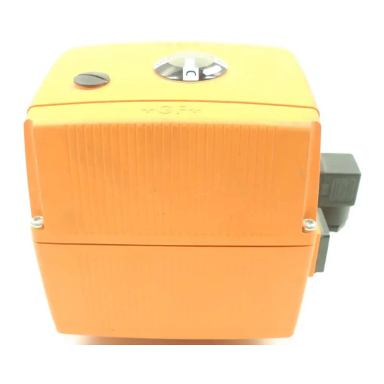
GF EA21 Instruction Manual

GF EA21 Instruction Manual

Electrical actuator

Advertisement

Index of content
1. Introduction .................................................................. 36
2. EC Manufacturer's Declaration .................................. 36
3. Intended use ................................................................. 37
4. Safety Information ....................................................... 37
5. Actuator Design ............................................................ 38
5.3 DIP switch in case of error ...................................................... 40
6. Setting Up the Actuator ............................................... 40
Electrical Actuator Type EA 21/31 ............................................. 42
7.5 Monitoring print ........................................................................ 52
.................................................................................. 60
8. TROUBLESHOOTING .................................................... 66
Ordering Information ....................................................... 67
...................................................................... 36
......................................... 37
........................................................................ 37
............................................................ 38
......................................................................... 39
...................................................41
.......................................................... 43
....................................................................... 44
........................................................................ 45
........................................................ 47
........................................... 48
.................................................................... 49
.............................................................. 58
............................................................................ 68
.................................... 39
37

Advertisement

Table of Contents
loading
Need help?

Need help?

Do you have a question about the EA21 and is the answer not in the manual?

Questions and answers

Subscribe to Our Youtube Channel

Summary of Contents for GF EA21

  • Page 1: Table Of Contents

    Index of content 1. Introduction ..............36 General Information ..............36 2. EC Manufacturer’s Declaration ........36 3. Intended use ..............37 4. Safety Information ............37 4.1 Due care required by the operator ......... 37 4.2 Special hazards ................ 37 4.3 Transport and Storage ............
  • Page 2: Introduction

    1. Introduction This instruction manual contains all the pertinent information on the de- sign, installation and operation of the electrical actuator type EA 21/31/42. General Information Hazard notices Hazard notices are used in this manual to warn you of possible injuries or damages to property.
  • Page 3: Intended Use

    Modifications to the actuator which have an effect on the technical data given in this instruction manual and its intended use, i.e. significantly alter the actuator, render this manufacturer’s declaration null and void. 3. Intended use When mounted on a valve and connected to a system control, the purpose of this actuator is to •...
  • Page 4: Transport And Storage

    In addition, the operating instructions of the manual valve must be observed. They are an integral component of this manual. 4.3 Transport and Storage The actuators must be handled, transported and stored with care. Please note the following points: • The actuators should be transported and/or stored in their original unopened packaging.
  • Page 5: Wiring Diagram For Standard Version

    5.1 Wiring Diagram for Standard Version Position indicator 3/2-way 2/2-way/BV horizontal vertical Releaiscontact max. 24V closed B−C B−C open A−C A−C A−B Installation note If the actuator is directly connected to the power supply, it is necessary to install a disconnector between the actuator and the power supply (do not disconnect the earth cable).
  • Page 6: Dip Switch In Case Of Error

    The two LEDs will go out and the actuator is ready to ope- rate again. 5.3 DIP switch in case of error In case of malfunc- In case of an error the actuator can be set to the CLOSED or tion the actuator the OPEN position with the help of the DIP switch.
  • Page 7: Emergency Manual Override

    When letting go the crank, the actuator is energized again. With 9 revolutions, the actuator EA21 turns by 90° With 27 revolutions the actuator EA31 turns by 90° With 41 revolutions the actuator EA42 turns by 90°...
  • Page 8: Dimensional Drawings Of The Electrical Actuator Type Ea 21/31

    6.2 Dimensional drawings of the Electrical Actuator Type EA 21/31/42 EA21 82.5 64.3 188.5 EA31 82.5 64.3 211.5 EA42 82.5 64.3 229.5 EA21/F05 EA31/F07 EA42/F07...
  • Page 9: Technical Specifications

    6.3 Technical Specifications EA21 EA31 EA42 Rated voltage 100 – 230V, 50/60 Hz 24V = /24V, 50/60 Hz Rated voltage tolerance +/- 10% Rated output @ 24V AC/DC 22 VA 32 VA 40 VA @ 100 – 230V AC 40 VA...
  • Page 10: Mounting And Connecting Supplementary Kits

    7. Mounting and Connecting Wiring diagram Supplementary Kits 7.1 Heating Element Description Technical data Code Heating element 24 V= 199 190 086 The heating element is mounted on the base board and is connected electrically via a flat cable (X1). The temperature is measured with a temperature sensor, which is mounted on this element, and between approx.
  • Page 11: Fail-Safe Return

    7.2 Fail-safe return Description Technical data Code Fail-safe return 24 V= 199 190 085 DIP switch The fail-safe return unit is mounted on the base board and is connected electrically via a flat cable. The fail-safe return unit is connected to the battery via a two-core wire.
  • Page 12 Mounting the fail-safe return (board) 1. Disconnect the actuator from the supply voltage. 2. Take the board out of its packaging and check for damages. Do not touch the board itself. Electrostatic discharge can damage the components. 3. Screw the three distance bolts (1) into the assembly bolts. Screw hand- tight.
  • Page 13: Additional Limit Switches

    7.3 Additional Limit Switches Wiring diagram Description Technical Code data Kit with 2 additional* 250 V ~, 6 A 199 190 092 limit switches Ag-Ni Kit with 2 additional* 30 V =, 100 mA 199 190 093 limit switches Au Kit with 2 additional 10-30 V=, 199 190 096...
  • Page 14: Additional 4 Limit Switches

    Setting the limit switch position 1. Reconnect the actuator to the supply voltage. The switch position may only be set with an extra-low voltage under 50 V. 2. Move the actuator to the two end positions and set the respective switching points. The switching cams can be adjusted with a screwdriver size 2.
  • Page 15: Middle Positioning

    7.4 Middle Positioning Description Technical data Code Middle positioning 199 190 094 The kit is mounted on the limit switches S1, S2 and serves to move the actuator to a third position ( e.g. 3-way ball valve into the middle position). Wiring diagram...
  • Page 16 Mounting the middle positioning kit 1. Disconnect the actuator from the supply voltage. 2. Remove the screws of the limit switches S1 and S2 Connect the plug of the kit to the four-pole slot (1). Make sure that the multipoint socket connector of the plug fits into the socket board of the four-pole plug.
  • Page 17 Setting the end positions Setting the opening angle from 90° to 180° • Turn switching cam 2 of switch S2 counter clockwise (top view) by 90°. • Reconnect the actuator to the supply voltage • Move the actuator into position “CLOSED” (terminal 2 under current) •...
  • Page 18: Monitoring Print

    7.5 Monitoring print BCD switch DIP switch Description Technical data Code Monitoring print 199 190 099 The monitoring print is mounted on the base board and is connected electrically with a flat cable. The monitoring print enables five functions: 1. Cycle time extension 2.
  • Page 19 Mounting the monitoring print Monitoring print kit 1. Disconnect the actuator from the supply voltage. 2. Take the board out of the packaging and check for dama- ges. Do not touch the board itself. Electrostatic discharge can damage the components. 3.
  • Page 20 Error message If an error occurs, the red LED (8) on the base board lights In case the monitoring print is installed, the LED (10) on the BCD switch which selected value has been exceeded will also light up red. With all occurring error messages the ready-to-operate signal will be off.
  • Page 21 (OPEN or CLOSED). The corresponding values are contained in the following table. These values apply for 90° angle. Cycle time without BCD: 5s for 90° (EA21); 15s for 90° (EA31); 25s for 90° (EA42) Switch setting Cycle time monitoring [s]...
  • Page 22 If the cycle exceeds the pre-set time, a failure is reported (see error message, page 20). For the corresponding value please refer to the table below (values are valid for 90° actuation). Switch setting Cycle time monitoring [s] EA21 EA31 EA42 Delivery position Delivery...
  • Page 23 (1) Delivery position EA21 Switch setting Number of cycles (2) Delivery position EA31 (3) Delivery position EA42 10.000 20.000 Reset „Number of Cycles“ 30.000 (3) 40.000 (2) Turn the BCD-Switch in the Po- sition O (Position corresponding 50.000 (1) to 1 Cycle). Drive the actuator 60.000...
  • Page 24: Position Signalization

    7.6 Position Signalization Description Technical data Code Position 199 190 084 signalization The position signalization enables determining the exact mechanical position of a valve. Output signal is a current of 4 – 20 mA. (4mA-CLOSED, 20mA-OPEN). The position signalization can be combined with the positi- oner or the monitoring print.
  • Page 25 Setting the position signalization For the position sensor (4) to recognize the OPEN and CLOSED positions, a single learning run with 360° must be done. After the learning run, the OPEN and CLOSED positi- ons are set. Further learning runs can be done between the end positi- ons (depending on the switching cams S1 and S2).
  • Page 26: Positioner

    During this run, the LED (6) will blink. While the LED (6) is blinking, the actuator is in the learning mode. The learning run is only finished when the LED lights continuously. If the position signalization is combined with the monitoring print, the output signal 4 –...
  • Page 27 Signal configuration The four DIP switches on the controller print serve for the configuration of the signals. DIP switch: S2 S3 S4 Switch combination Signal type S1 0-10 V 4-20 mA ON: input inverted OFF: input not inverted ON: use S3L Master OFF: use S3L Slave Example: Set signal value 4 –...
  • Page 28 Description Technical data Code Positioner type PE 25 galvanic isolated 199 190 101 The positioner type PE 25 controls a user-defined valve position proportio- nal to a given set value. This can be 0-10V or 4-20mA. The return of the valve position (actual value) is realized with the position signalization.
  • Page 29 Signal configuration The four DIP switches on each of the three switch blocks on the controller print serve for the configuration of the signals. DIP Schalter Block 1 - 3: S2 S3 S4 Switch combination DIP switch All switches must Block 1 be set to OFF S2 S3 S4...
  • Page 30 Mounting the positioner Disconnect the actuator from the supply voltage. 2. Take the controller board out of the packaging and check for damages. Do not touch the board itself. Electrostatic discharge can damage the components. 3. Place the board vertically on the back side of the base board on plug X1.
  • Page 31 Terminal assignment Positioner 199 190 101: SET value input current / voltage Output 12 V DC SET value input ground Position signalization signal Position signalization ground Mind the configuration of the set value The 4 – 20 mA current signal at the terminals 30, 31 can be evaluated, if necessary.
  • Page 32 Setting the position signalization For the position sensor (4) to recognize the OPEN and CLOSED positions, a single learning run with 360° must be done. After the learning run, the OPEN and CLOSED positions are set. Further learning runs can be done between the end posi- tions (depending on the switching cams S1 and S2).
  • Page 34: Troubleshooting

    8. TROUBLESHOOTING Problem Possible causes Remedy Motor does not run no mains voltage available error at customer side (terminals 1,2,3) internal wiring error check wiring of actuator switching cams S1 and S2 see point 6 set incorrectly motor blocked use emergency manual override, check the valve Motor only runs in limit switch defective...
  • Page 35: Ordering Information

    Ordering Information Description Code Actuator EA21 100–230 V~ 198 150 182 Actuator EA21 24 V=/~ 198 150 183 Actuator EA31 100–230 V~ 198 150 184 Actuator EA31 24 V=/~ 198 150 185 Actuator EA42 100–230 V~ 198 150 186 Actuator EA42 24 V=/~...
  • Page 36: Notizen/Notice/Note

    Notizen/Notice/Note...
  • Page 37 Notizen/Notice/Note...
  • Page 38 GF Piping Systems > worldwide www.piping.georgfischer.com Australia Georg Fischer Georg Fischer Schwab GmbH & Latin America / Caribbean Sweden / Finland Co. KG George Fischer Pty Ltd Piping Systems Ltd Shanghai George Fischer Inc. Georg Fischer AB Kingsgrove NSW 2208...

This manual is also suitable for:

Ea31Ea42

Table of Contents