
Related Manuals for GF Intelek-Pro SIGNET 9010


Summary of Contents for GF Intelek-Pro SIGNET 9010
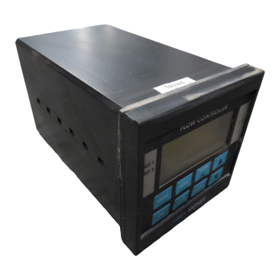
- Page 1 + GF + SIGNET 9010 Intelek-Pro Flow Controller FLOW CONTROLLER + GF + SIGNET Instruction Manual GEORGE FISCHER + GF +...
- Page 2 Important safety information Danger: Avoid electric shock. Do not connect power when the instrument cover is partially or completely removed.
-
Page 3: Table Of Contents
Table of Chapter Page Contents Introduction 1.1 Introduction 1.2 Front Panel Description 1.3 Rear Panel Description Installation and Operation 2.1 Mounting Instructions 2.2 Power Connections 2.3 Input Connections 2.4 Standard Output Connections 2.5 Relay Output Connections 2.6 Verifying Analog Outputs 2.7 Analog Output Connections System Configuration 3.1 Introduction... - Page 4 Unpacking and Inspection Your flow controller package includes the following items: • + GF + SIGNET 9010 Intelek-Pro Flow Controller • Two stainless steel mounting brackets • Mounting Instructions w/self-adhesive template • Panel gasket • Instruction manual w/assorted engineering labels...
-
Page 5: Introduction
The + GF + SIGNET 9010 Intelek-Pro Flow Controller is fully compatible with all + GF + Signet The technical data given in this publication is for general flow sensor products, yet also accepts other information purposes only. -
Page 6: Front Panel Description
ENTER window. The unit tags are attached RELAY OUTPUT to the rear cover of the manual. + GF + SIGNET Item Function 1. Relay An- Indicate activation status of optional output "alarm" relays 1 & 2 nunciators: 2. LCD Shows flow, calibration, accumulation, and relay activation status information... -
Page 7: Rear Panel Description
1.3 Rear Panel Description ANL2 SERIAL OUTPUT A in SENSOR R+ R- BLK RED SHLD SS CNT GND PLS Tx GND Rx A+ A- Note: Rear terminals 10 11 12 13 14 accept 18 to 22 AWG wire 1 5 1 6 1 7 1 8 1 9 2 0 2 1 2 2 2 3 2 4 2 5 2 6 2 7 2 8 + GND NO C NO C AC IN... -
Page 8: Installation And Operation
2.1 Mounting Instructions Chapter 2 The + GF + SIGNET Intelek-Pro Flow Controller's 1/4 DIN enclosure is specifically designed for Installation panel mounting. Adjustable mounting brackets allow mounting in panels up to 1 in./25 mm thick. An adhesive template and instructions are included Operation to insure proper installation. -
Page 9: Power Connections
2.2 Power Connections AC Power Connections Figure 2 AC Hot 90 to 132 VAC AC power wiring AC Ground* 180 to 264 VAC AC Neutral 1 5 1 6 1 7 1 8 1 9 2 0 2 1 2 2 2 3 2 4 2 5 2 6 2 7 2 8 + GND NO DC IN RLY1... -
Page 10: Input Connections
R+ R- BLK RED SHLD Tx GND Rx A+ A- 10 11 12 13 14 Analog Input: Current or Voltage External DC + GF + SIGNET Power Supply 8512 BLACK Frequency Input: To reduce the possibility of & for Signet sensors... -
Page 11: Standard Output Connections
The sensor pulse output (PLS) emits a standard TTL frequency output in phase with the sensor input and can be used to drive + GF + SIGNET instruments (except + GF + SIGNET 5090 and 5091) and other TTL compatible devices. -
Page 12: Relay Output Connections
2.5 Relay Output Connections The 2-Relay option provides two relays for external device control. Each relay's contacts are rated for 5 A maximum. Both NO and NC contacts may be used individually or simultaneously as shown. Figure 6 2-Relay wiring Device A Device A is powered during External... -
Page 13: Verifying Analog Outputs
2.6 Verifying Analog Outputs Installed analog output options can be configured to either of the unit's rear analog output terminals: ANL1 or ANL2. Configuration is determined by which sockets the options are installed. Options installed in option socket #1 are configured to the rear ANL1 terminals, options installed in socket #2 are configured to the rear ANL2 terminals (see section 4.3). -
Page 14: Analog Output Connections
2.7 Analog Output Connections 0 to 20/4 to 20 mA isolated or non-isolated output as well as 0 to 5/0 to 10 VDC isolated or non-isolated outputs are available. See section Figure 7 4.4 for a list of available output cards. Analog output wiring ANL2 SERIAL... - Page 15 setpoint, hysteresis etc. The OUTPUT menu provides access to the functions which define and control all analog output signals, i.e. 4 to 20 mA, 0 to 5 VDC etc. CAL Menu RELAY Menu OUTPUT Menu RELAY OUTPUT (frequency) (LO/HI) • Minimum flow rate •...
-
Page 16: Calibration Menu, Frequency Inputs
3.2 Calibration Menu, Frequency Inputs Legend Security Unlock security = Press Keypad ENTER Code? code using: 1 8 8 8 8 = Intelek-Pro Display X X X X X X X X Press 1 9 9 9 9 Modify? set K-factor from = Decision ENTER K - F A C T O R... - Page 17 Press 1 8 8 8 8 Modify? enter minimum ENTER 4 m A I S flow rate Recall original value Select next item? FLOW Normal operation Press 1 8 8 8 8 Modify? enter maximum ENTER 2 0 m A flow rate Recall original value Select...
- Page 18 - - - . - - Press to select Modify? display decimal, ENTER F L O D P = 2 0-4 places Recall original value Select next item? FLOW Normal operation 1 8 8 8 8 Press to select Modify? ENTER best contrast C O N T R A S T...
-
Page 19: 2-Relay Operations
3.4 2-Relay Operations Figure 8 LO relay operation mode The 2-Relay option allows you to configure individual setpoints, LO or HI operation, and Flow hysteresis values for two independent on/off relays. • Relay Setpoints: Setpoints represent the flow rate at which each relay is energized. •... -
Page 20: Calibration Menu, 2-Relay
3.5 Calibration Menu, 2-Relay Yes Unlock security Security RELAY ENTER code using: Code? Press to select Modify? relay operation mode ENTER R L Y 1 LO, HIGH, or PULSE Recall original value Select PULSE next RELAY Mode item? Go to FLOW Normal operation Note:... -
Page 21: Calibration Menu, Analog Outputs
3.6 Calibration Menu, Analog Outputs 4 to 20/0 to 20 mA (iso/ non-iso) options illustrated Unlock security Security ENTER OUTPUT code using: Code? Press to select 9 9 9 9 Modify? flow rate at 4 mA ENTER A N L 1 output signal Recall original value Select... -
Page 22: View-Only Menus
3.7 View-Only Menus Three "view-only" menus (CAL, RELAY, and Note: The view-only menus OUTPUT) are available during normal operation. are designed for viewing only and DO NOT permit access Each view only menu provides the operator a for calibration of any kind. means of browsing through calibration settings Menus will vary depending without disturbing system calibration and/or the... -
Page 23: Technical Support
4.1 Accessing Internal Options Chapter 4 1. Remove bezel (1) by placing a coin in the notch (2), twist coin to remove the bezel from the Technical instrument casing. See Figure 11 Support 2. Loosen the four front bracket screws (3), then loosen the center "jack-screw"... -
Page 24: Installing Input/Output Options
Figure 14 Main PC Board Option Sockets Security Feature OUTPUT CARD #1 OPEN Enable the security feature by setting positon #1 "closed" OPEN Disable the security feature by setting OUTPUT CARD #2 positon #1 "open" Blue Jumpers 90 to 132 VAC 180 to 264 VAC Fuse, 1/4 A @ operation... -
Page 25: Option Cards And Accessories
0 to 10 VDC (isolated) 198 840 636 3-9000.440-1 2-Relay card 198 849 641 Part Number Accessories Code + GF + SIGNET mounting 3-5000.399 198 840 224 adapter plate 3-5000.395 NEMA 4X/IP65 back cover 198 840 227 3-9010.650 Assorted engineering labels 198 840 205 3-9000.392... -
Page 26: Input Card Configuration
No power to sensor with no 2515 pulldown resistor 2717 2000 1001 5 VDC power to sensor 2507 with pull up resistor 2536 Frequency 2540 Input Card 2550 Dip Switch *Dip switch factory configured for the + GF + SIGNET 515 Rotor-X Paddlewheel Flow Sensor. -
Page 27: Output Card Configuration
4.6 Output Card Configuration Figure 16 4 to 20/0 to 20 mA output Each 4 to 20/0 to 20 mA (iso or non-iso) output cards card contains jumper selections for it's operation Non-isolated range. version Isolated version • Placing the blue jumper in the "A" position Blue configures the card for 4 to 20 mA operation. -
Page 28: Specifications
Specifications Power Requirements 17 to 30 VDC @ 0.5 A max. and/or 90 to 132 VAC @ 50 to 60 Hz or 180 to 264 VAC @ 50 to 60 Hz Operating Temperature 32 to 130 °F/0 to 55 °C Relative Humidity 95% R.H. - Page 29 Isolated freq input: 0.5 Vp-p Isolation: 500 VDC to earth ground Flow Current and Voltage (iso): Input range: 4 to 20 mA or 0 to 20 mA 0 to 5 VDC or 0 to 10 VDC Isolation: 500 VDC isolation to earth ground Output Signals Sensor Pulse Output TTL compatible synchronous with sensor input...
-
Page 30: Warranty Information
U.S. Warranty Limited Two-Year Warranty Signet Scientific Company warrants its instruments Information to be free from defects in material and workmanship under normal use for a period of two years from the date of purchase by the initial owner, or three years from date of manufacture, whichever comes first, as described in the following paragraphs. - Page 31 Signet Scientific Company shall have the sole right to determine whether in fact a warranty situation exists. Signet Scientific Company is continually making design changes and improvements that adapt to the original circuit configuration. These will be incorporated as required in older units on a minimal charge basis while under warranty.
- Page 32 Notes:...
- Page 33 Notes:...
- Page 34 Notes:...
- Page 36 Tel. 61/3 9568 0966, Fax 61/3 9568 0988 Signet Scientific Company, 3401 Aerojet Avenue, El Monte, CA 91731-2882 U.S.A., Tel. (626) 571-2770, Fax (626) 573-2057 PRINTED ON RECYCLED PAPER GEORGE FISCHER + GF + Piping Systems © Signet Scientific Company 1993 Printed in U.S.A. 3-9010.090...
Need help?
Do you have a question about the Intelek-Pro SIGNET 9010 and is the answer not in the manual?
Questions and answers