Table of Contents
Advertisement
Quick Links
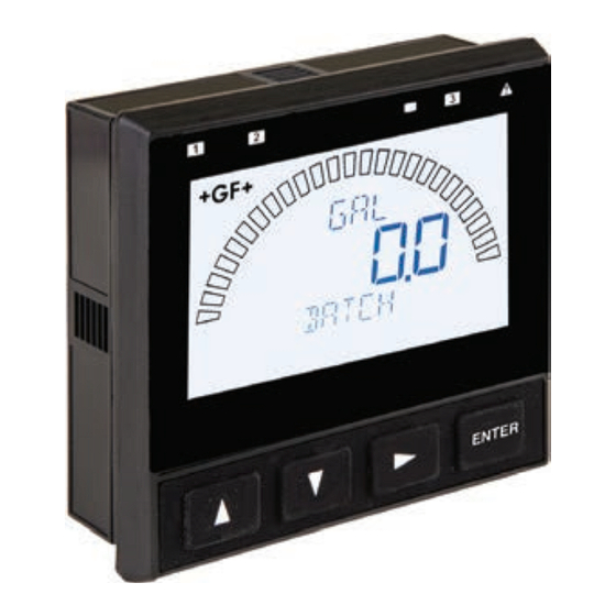
Signet 9900-1BC Batch Controller System
*3-9900-1BC.090*
3-9900-1BC.090-1 Rev. 6 05/20
Panel Mount
• English
• Deutsch
• Français
• Español
中文
•
English
Compatibility
The Signet 9900-1BC Batch Controller is compatible with the Signet models
515 (8510), 525, 2536 (8512), 2537 and 2540 paddlewheel fl ow sensors,
models 2551 and 2552 insertion magmeters, 2580 FlowtraMag meter and
models 2000, 2507, and 2100 in-line fl ow sensors.
Description
Your new 9900-1BC Batch Controller system includes the following items:
• Signet 9900 Transmitter (3-9900-1P)
• Signet Relay Module (3-9900.393)
• Signet Batch Module (3-9900.397)
Note:
Batch Module requires Generation II or later, 9900 transmitter.
Verify 9900 Transmitter generation under the OPTIONS Menu.
CAUTION:
In the event of a power failure, please review
the batch settings before resuming a batch.
Failure to do so could result in an overfi ll of
the container.
Product Manual
Look for the Quick Start icon to
quickly set up your new 9900-1BC.
English
Advertisement
Table of Contents

Related Manuals for GF Signet 9900-1BC


Summary of Contents for GF Signet 9900-1BC
-
Page 1: Compatibility
9900-1BC. Compatibility The Signet 9900-1BC Batch Controller is compatible with the Signet models 515 (8510), 525, 2536 (8512), 2537 and 2540 paddlewheel fl ow sensors, models 2551 and 2552 insertion magmeters, 2580 FlowtraMag meter and models 2000, 2507, and 2100 in-line fl ow sensors. -
Page 2: Table Of Contents
Safety Information ............1 All warranty and non-warranty repairs being returned Warranty Information ..........2 must include a fully completed Service Form and goods must be returned to your local GF Sales office Product Registration ..........2 Dimensions ...............3 or distributor. Installation ..............3 Product returned without a Service Form may not be warranty replaced or repaired. -
Page 3: Dimensions
Dimensions 29.97 mm 99.06 mm (1.18 in.) (3.90 in.) 54.10 mm (2.13 in.) 91.44 mm 99.06 mm (3.60 in.) (3.90 in.) 8.13 mm (0.32 in.) Installation System Start-up: Step 1 Prepare the Controller installation location. If the back of the Controller is difficult to access when installed, wire the removable terminal plugs first, then attach to 9900 Transmitter. -
Page 4: Modules
Modules Batch Module Convert a 9900 Transmitter (Generation II or later) to a Batch Controller by plugging in a Batch Module 3-9900.397 (159 310 163). Optional Module Wiring: • Wire an external button or keypad (customer supplied) to stop, start or resume a batch remotely. •... -
Page 5: Terminal Identification
Terminal Identification Terminals 1-2: DC Power • Required by the instrument • Provides power to sensors, relays and the LCD backlight Terminals 3-4: 4 to 20 mA • Passive 4 to 20 mA output The 9900-1BC requires Terminals 5-6: Open Collector regulated 10.8 to 35.2 VDC (24 VDC nominal) from •... -
Page 6: Software
Proper operation of the batch module requires Generation II, version 25-04 software in the 9900 Transmitter. To determine the software version of the 9900 Transmitter, please see instructions below. If your unit has an older version of software, please contact your local GF sales office for upgrade instructions. Note: The 9900 in Batch mode does not support the 3-9900.270-MX Modbus or the 3-9900.395 HART Communication modules. -
Page 7: Wiring
Wiring System Start-up: Step 2 Wire the transmitter connections with the power off. Keep any 4 to 20 mA and relay-actuated output devices that are connected to it offl ine at this time. Wire the sensor (pg. 8), power (pg. 9) and Open Collector and relay(s) (pg. -
Page 8: Sensor Wiring
2536 2540 2536 2536 2540 2540 Frequency Sensor Wiring FLOW FLOW Frequency Frequency 2551* 2750 2850 Black 515 (8510), 525, 2000, 2100, 2507, White 2536 (8512), 2540 Shield * 2551-XX-21, -41 Display Magmeter 2000 2000 2100 2100 2507 2507 2507 Black Black Black... -
Page 9: Power Wiring
2580 Black – Power cable 24 VDC @ 1A min. Power Supply Sensor Wiring 2580 ® • When choosing Frequency in the Bluetooth App, 2580 Data (Red) the 2580 outputs an open collector frequency 9900 Ground - (White) signal that can be connected to the 9900-1BC. Output cable Terminals Power... -
Page 10: Relay And Open Collector Wiring
Open Collector Wiring Open Collector Wiring • Longer life than a mechanical relay • No moving parts • Faster ON/OFF switching capabilities than mechanical relays • Can switch DC voltage only (< 30 VDC, < 50 mA) • Not recommended for use with inductive loads Fail-Safe Behavior No matter the setting, the Open Collector output turns off if the 9900 loses power. -
Page 11: Relay Module Wiring
Relay Module Wiring The alarm is OFF during normal ALARM! operation, and will go ON when relay energizes according to AC or DC 9900 Relay settings. power Process High Setpoint The valve is ON during normal Hysteresis operation, and will go OFF when relay energizes according to 9900 Relay settings. - Page 12 Process High Limit Hysteresis Relay Mode Settings Window 100% 100% Low Limit Process HI FLOW – High Flow: Advanced Mode High Time (See Input Menu - Page 19) In HI FLOW Mode, Relay is energized at Set Flow Setpoint value and will be de-energized at Set Flow value Hysteresis minus Hysteresis value.
- Page 13 Time Time Time Relay Mode Settings 100% Overrun Process TOT VOL – Totalizer Volume: Advanced Mode High Limit Hysteresis (See Input Menu - Page 19) When resettable totalizer exceeds specified volume, Window relay activates and latches. Low Limit Time 100% Overrun Requires Totalizer Volume Reset to deactivate relay Process...
-
Page 14: Operation
Operation Open Collector (R1) Indicator LED Backlight Sensor (do not block) Mechanical Relay (R2) Mechanical Relay (R3) Indicator LED Indicator LED Warning LED Bar Graph Units of Measure (GPM, sec, %, etc.) Value Label Menu Indication Menu Navigation Keys ENTER UP, DOWN keys Scroll through Menu options or adjust values during editing. -
Page 15: System Setup Menu
System Setup ENTER System Setup: Menu Navigation Edit This basic operating procedure repeats throughout the 9900 program: 1. Press ENTER for 3 seconds to enter EDIT menu. 2. Press ► to move to a specific menu item. 3. Press ENTER key to select the item for editing. 4. -
Page 16: Menu System
Menu System VIEW Mode Overview Error Handling The top level of menus is referred to as the VIEW Mode. This view displays Errors occurring while in the VIEW Mode show a specific measurement values as well as current outputs and relay status. The radial bar graph represents the measurement value that is also displayed in the 7-segment message (e.g., CHECK numeric field below the bar graph. -
Page 17: View Mode Menu - Batch Running
Menu System BATCH Setup Checklist 1. Set the Units of Measure in Input Menu. 2. Set Flow Timebase in Input Menu. 3. Set Sensor Type (Freq or S L) in Input Menu. 4. Set Batch Size in Input Menu. 5. Set K-Factor (pulses per Unit Volume) from Flow Sensor manual in CAL Menu. -
Page 18: View Mode Menu - Batch Stopped
VIEW Mode Menu - Batch Stopped Start Batch Press Up or Down arrows to select the desired batch number. Press ENTER to start selected batch. Selected batch alternately displays on the bottom line of the display. (Confirmation screen or password screen are user-selectable in INPUT menu.) Available batches determined by the number of stored batches whose size is not zero. -
Page 19: Cal Menu
CAL Menu K-Factor Set K-Factor (pulses per unit volume) according to Flow Sensor manual. Min: 0.0001, Max: 999999. Cannot be zero. Default = 60.0000. In Simple Mode, the K-Factor will be used for all batches. In Advanced Mode, there is one K-Factor for each stored batch. -
Page 20: Loop Menu
INPUT Menu Mode Select Select ADVANCED or SIMPLE Mode. ADVANCED Mode enables additional features in RELAY and LOOP Modes. Default = SIMPLE. Count Up/Down Select count direction of Batch Volume and Percent Complete (Source Volume always counts down). Default = Count Up. Note: If Count Down is selected, Dispensed volume and Source volume can display negative values. -
Page 21: Relay Menu
RELAY Menu R1 Normal Open/Closed Set Open Collector (R1) as Normally Open or Normally Closed. Default = NORMAL OPEN. Relay Mode Select the desired mode of operation for the open-collector (R1) output. Simple Mode: BATCH, VOL PULS, MISSING. Advanced Mode: OFF, BATCH, HI FLOW, VOL PULS, EOB PULS, MISSING, OVERRUN, SRC VOL (if SOURCE VOL is set to ON;... -
Page 22: Relay Multiple Mode
RELAY Menu RELAY MULTIPLE Mode options (see discussion on page 13) Missing Signal On/Off Energizes selected relay if signal is missing. Select ON or OFF. Overrun On/Off Energizes selected relay if overrun occurs. Select ON or OFF. Hi Flow On/Off Energizes selected relay if Hi Flow condition occurs. Select ON or OFF. Error On/Off Energizes selected relay if an error condition occurs. -
Page 23: Option Menu
OPTION Menu Contrast Adjust the LCD contrast for best viewing. A setting of 1 is lowest contrast, 5 is highest. In general, select lower contrast if the display is in warmer surroundings. Default = 3. Backlight Adjust backlight level. Select OFF, LOW, HIGH or AUTO. Default = AUTO. Batch Decimal Set the decimal to the best resolution for your application. -
Page 24: Error Messages
Error Messages Remote Batch Module is missing. No signal from Flow Sensor. External Stop signal is preventing batch start or Remote Stop button is held down. Bypass relay must be set on Bypass Relay Select option, under the Relay Menu. See page 21, under Relay Two Stage mode. -
Page 25: Calibration
Calibration NOTE: In Advanced Mode the Batch Controller has a separate K-Factor for each stored batch. In Simple Mode the stored batches use a common K-Factor. If you switch from Simple Mode to Advanced Mode, the single K-Factor will be copied to the K-Factor for each batch. -
Page 26: Specifications
Specifications General Environmental Requirements Input channels .....One Ambient operating temperature: Backlit LCD ......-10 °C to 70 °C (14 °F to 158 °F) Enclosure and Display Storage Temp ...... -15 °C to 70 °C Case Material ......PBT (5 °F to 158 °F) Window ........Shatter-Resistant Glass Operating Temp .... - Page 27 Specifications Output Specifications Standards and Approvals CE, UL, CUL One 4 to 20 mA output Current Loop Out ....ANSI-ISA 50.00.01 Class H RoHS compliant Span ........3.8 to 21 mA Manufactured under ISO 9001 for Quality, Zero ........4.0 mA factory set; ISO 14001 for Environmental Management and OHSAS user programmable from 18001 for Occupational Health and Safety.
-
Page 28: Ordering Information
Ordering Information 9900-1BC Batch Controller System Mfr. Part No Code Description 3-9900-1BC 159 001 770 9900-1BC Batch Controller System 3-9900-1P 159 001 695 9900 Panel Mount Transmitter 3-9900.393 159 001 698 Relay Module - 2 DCR (dry-contact relays) 3-9900.397 159 310 163 Batch Module Accessories Mfr.
Need help?
Do you have a question about the Signet 9900-1BC and is the answer not in the manual?
Questions and answers