Advertisement
Quick Links
+ GF + SIGNET 5600 Batch Controller Instructions
3-5600.090-1
B-1/98
CAUTION!
• Refer to this instruction manual for more details.
• Remove power to unit before wiring input and output connections.
• Follow instructions carefully to avoid personal injury.
Contents
1.
Dial Selection
2.
Power Connection
3.
Compatible Sensor Wiring
4.
Batch Contact Wiring
5.
6.
7.
8.
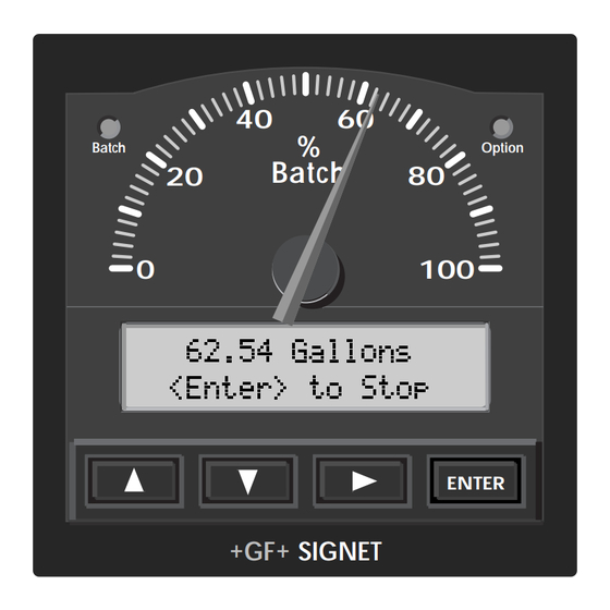
1. Dial Selection
The analog display shows percentage of batch complete 0 - 100%, or
percentage of remaining batch 100 - 0% on the reversible dial face
plate. Meter deflection is fixed from left to right. The instrument is
shipped with the percentage of batch complete 0 - 100% scale shown.
Reverse the face plate for either scale, as desired.
A
3. Compatible Sensor Wiring
Std. Sensor
Open Collector
Sensor
Technical Notes:
• To reduce the possibility of noise interference, route sensor cable
away from AC power lines.
• *Vortex sensor or system frequency output
D
C
B
+ GF + SIGNET Sensors:
Red
515
525
Black
2517
Shld.
2000
Red
2507
Black
2536
Shld.
2540
Vortex*
5600
Terminals
9.
5600 Operation Modes
14. Maintenance
15. Troubleshooting
2. Power Connection
CAUTION!
Never connect 115 VAC or 230 VAC to rear power
terminals. High voltage AC will damage instrument and
void warranty.
= Double Insulated
= DC or AC power
Technical Notes:
• Maximum 4-20 mA loop impedance (sec. 8A) is affected by the
supply voltage.
• To reduce the possibility of noise interference, isolate AC power
lines from signal lines.
4. Batch Contact Wiring
See section 9 for simple and advanced mode configuration options.
Option
NO
C
NC
flow
Technical Notes:
• Maximum alarm contact ratings: 5 A @ 30 VDC, 5 A @ 125 VAC,
or 3 A @ 250 VAC
• To reduce the possibility of noise interference, isolate AC power
lines from signal lines.
5600
Terminals
12-24 V
10 W
External power
supply
-
+
-
12 - 24 VDC
OR
12 - 24 VAC
+
5600
Terminals
Batch
NO
C
NC
AC or DC
power
valve
ENGLISH
Advertisement

Subscribe to Our Youtube Channel
Related Manuals for GF SIGNET 5600


Summary of Contents for GF SIGNET 5600
-
Page 1: Table Of Contents
+ GF + SIGNET 5600 Batch Controller Instructions ENGLISH 3-5600.090-1 B-1/98 CAUTION! • Refer to this instruction manual for more details. • Remove power to unit before wiring input and output connections. • Follow instructions carefully to avoid personal injury. -
Page 2: Remote Control Wiring
5. Remote Control Wiring 6. End of Batch/Counter Pulse Output Wiring Momentary Switch Contacts Rear START, STOP, and RESUME See section 9 for simple and advanced mode configuration options. (customer supplied) (Rsm) terminals can provide remote batch control from a distance using Start A. - Page 3 Section 7 Continued... Section 8 Continued... C. End of Batch Pulse (advanced mode only, sec. 9.2) C. End of Batch Pulse (advanced mode only, sec. 9.2) Daisy chaining two 5600 batch controllers together for a second Daisy chaining two 5600 batch controllers together for a second batching stage.
- Page 4 • Option Contact - Two Stage Shutdown (sec. 7A): This function is designed to prevent Option Contact: over filling or to minimize water hammer. Both the batch and the option contact are Batch running... Two Stage 100% energized when the batch starts. The option contact then de-energizes at a programmed batch percentage, forcing flow through a smaller bypass line to reduce the fill rate.
-
Page 5: Menu Functions
10. Menu Functions Menus: *Note: BATCH/VIEW Menu steps B - E MUST be selected for CALIBRATE Menu (sec. 10.2) or OPTIONS Menu (sec. 10.4) access. • BATCH/VIEW menu (sec. 10.1): The BATCH/VIEW menu is displayed during standard operation. The ENTER key controls batch start, batch stop, and batch resume operations. - Page 6 XX.XXX Gallons *Note: Batch and totalizer K-Factor settings represent the number of (sec.10.4E) and manual overrun comp. (sec.10.4G) pulses generated by the + GF + SIGNET flow sensor for each ENTER is selected. D. Overrun comp. Save engineering unit of fluid measured (published in the flow sensor manual).
- Page 7 10.4 OPTIONS Menu (factory defaults shown in menu column 1) Press keys in sequence to continue, OPTIONS: -- -- -- -- Enter Key Code **** will appear during code entry. ← Back to step F Choose: Change: Save: Set overrun K↓...
-
Page 8: Parts And Accessories
• Front snap-on bezel, #3-5000.525 (code 198 840 226) • 5600 instruction sheet #3-5600.090-1 (code 198 869 929) 12. Specifications Agency Approvals General All + GF + SIGNET flow sensors Sensor compatibility: • CE ± 0.5% of batch reading Accuracy: •... -
Page 9: Quick Reference Menu Parameters
( 3 . 6 2 12-24 V x 3 . 6 10 W 2 i n . ) Option Batch + GF + SIGNET Model #3-5600 Panel Rear cutout View 13. Quick Reference Menu Parameters 13.1 VIEW Menu Setup Parameters (sec. 10.1) - Page 10 13.2 CALIBRATE Menu Setup Parameters (sec. 10.2) Menu Display Factory Range Parameters Default Description _ = blank display Batch units Aa - Zz, 0 - 9, /, _ _Gallons Batch Units: digit option (8-digits max.) Gallons > Flow timebase Ss, Mm, Hh, Dd Flow Timebase: >...
- Page 11 14. Maintenance Clean the instrument case and front panel with a soft cloth and mild liquid soap solution. 15. Troubleshooting Display Problem Solution -- -- -- --Gallons/m Display timebase too large Change flow timebase (S=Seconds, M=Minutes, H=Hours, D=Days) in <ENTER> to START CALIBRATE menu to a smaller value (e.g.
- Page 12 Provided by: KTH Sales, Inc. www.KTHSales.com ph: 219-736-0060 8574 Louisiana Place Merrillville, Indiana 46410 - USA Signet Scientific Company, 3401 Aerojet Avenue, El Monte, CA 91731-2882 U.S.A., PRINTED ON RECYCLED PAPER 3-5600.090-1/(B-1/98), English © Signet Scientific Company 1996 Printed in U.S.A.
Need help?
Do you have a question about the SIGNET 5600 and is the answer not in the manual?
Questions and answers