Table of Contents
Advertisement
Quick Links
IMPORTANT: Read entire instructions before program-
ming the sensor.
GENERAL
Carrier's T58 communicating room sensors are wall-
mounted, low-voltage sensors which maintain room tempera-
ture by communicating with the controller that operates the
HVAC (heating, cooling and ventilation) equipment. The T58
sensor provides a custom liquid crystal display (LCD)
and 4 push-buttons allowing user interface and feedback
capabilities
.
During power interruption, the T58 sensor stores config-
uration parameters in non-volatile memory, allowing coor-
dinated control to resume after power is restored. The T58
sensor utilizes universal graphical icons on the LCD.
OPERATION
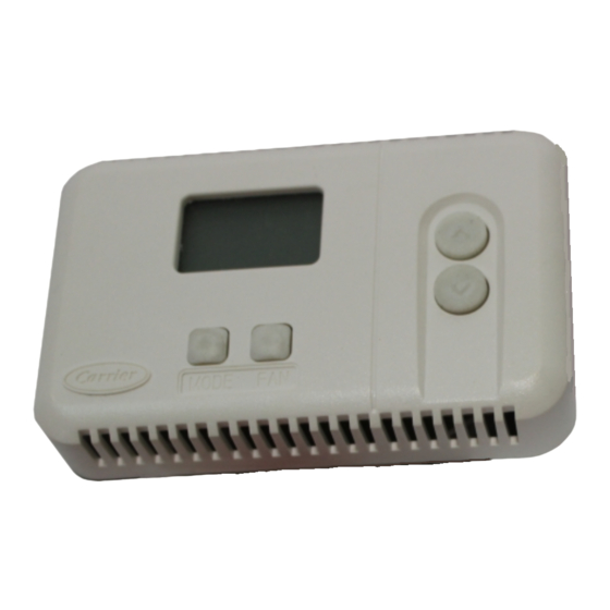
Sensor Display —
The sensor's LCD is located in the
top center of the sensor. See Fig. 1. The T58 sensor can display
the following information on the screen:
• Current space temperature (default LCD display)
• Unit mode of attached device
• Heating or cooling set point value — read from attached
device
• Outside air temperature — relayed from the connected
Carrier Network
• Current Fan mode — read from attached device
• Indication when time schedule override is in effect
• Set of error indications
MODE FAN
Fig. 1 — T58 Sensor
Manufacturer reserves the right to discontinue, or change at any time, specifications or designs without notice and without incurring obligations.
PC 111
Book 1
4
Tab
11a 13a
Owner's Manual
Part Number 33ZCT58SPT
INC
DEC
Catalog No. 533-383
Printed in U.S.A.
T58 Communicating
Sensor Programming Buttons and Opera-
tion —
The T58 sensor has programming buttons which are
used to change the set points of the equipment, change the fan
mode, and override schedules. The programming buttons are
located on the sensor cover. The programming buttons are:
FAN, MODE, INC and DEC. See Fig. 1.
The INC and DEC buttons are used to change the current
temperature set point and to scroll through programming
options. The INC and DEC buttons are on the outside of the
sensor.
READ CURRENT OPERATING MODE — Perform the
following to read the current operating mode of the attached
device:
1. Press the MODE button. The present operating mode
condition will be read in from the attached device. A
graphical icon will represent the operating mode. See
Fig. 2. A list of possible modes with the accompanying
icons for different attached devices is shown in
Tables 1-3. The current operating mode icon will be dis-
played for ten seconds then disappear, denoting the end of
the operation.
2. If there is no response from the CCN communications
request, then an error code of "E3" will be shown in the
numeric portion of the LCD area. Any error indication
will terminate after 5 seconds, and return to the default
Space Temperature display.
NOTE: This is a read only mode. Current operating mode
cannot be changed.
DISPLAY SPACE TEMPERATURE — The default display
of the T58 sensor shows the sensed temperature from its on-
board thermistor, which represents the Space or Room Air
Temperature. Any configured "trim" from the attached device
will not have an effect on this temperature value. This value is
updated every second by the T58 software and is sent out to
the attached device every minute or whenever its value
changes by .3 F. Temperature values will be stored with a pre-
cision of .1 F. The Space Temperature value will also be sent to
the attached device during any power on reset operation. If the
on-board thermistor fails, then the LCD will display a value of
"E1", indicating that the thermistor is no longer working. The
T58 sensor will continue to try to read the thermistor every
second.
Form 33ZC-3SO
Pg 1
Room Sensor
7-01
Replaces: 33ZC-2SO
Advertisement
Table of Contents

Related Manuals for Carrier 33ZCT58SPT


Summary of Contents for Carrier 33ZCT58SPT
- Page 1 The programming buttons are: FAN, MODE, INC and DEC. See Fig. 1. Carrier’s T58 communicating room sensors are wall- mounted, low-voltage sensors which maintain room tempera- The INC and DEC buttons are used to change the current...
- Page 2 To change Fan mode when User Control mode is enabled: 1. Press the INC or DEC button to cycle between Fan On, Fan Off, or Auto. A blinking “fan” icon indicates Auto mode (Fan only — no curved lines). 2. Press the FAN button again to complete the operation and send the new Fan mode to the attached device.
- Page 3 Table 1 — VAV Air Terminal Controller VAV MODE T58 ICON OFF (0) CIRCLE with enclosed | HEAT (1) SUNSHINE WARM-UP (2) SUNSHINE VENT (3) FAN ALONE FAN & VENT (4) FAN with 2 lines COOL (5) SNOWFLAKE DEHUMID (6) WATER DROPLET REHEAT (7) SUNSHINE...
- Page 4 The user needs to determine the problem and rectify the situation. LEGEND Carrier Comfort Network CCN — Copyright 2001 Carrier Corporation Manufacturer reserves the right to discontinue, or change at any time, specifications or designs without notice and without incurring obligations. Book 1 PC 111 Catalog No.
Need help?
Do you have a question about the 33ZCT58SPT and is the answer not in the manual?
Questions and answers