Table of Contents
Advertisement
Quick Links
SYSTXCCSMS01---A
Infinityr Smart Sensor for Zoning
NOTE: Read the entire instruction manual before starting the
installation.
SAFETY CONSIDERATIONS
Improper installation, adjustment, alteration, service, maintenance,
or use can cause explosion, fire, electrical shock, or other
conditions which may cause death, personal injury or property
damage. Consult a qualified installer, service agency or your
distributor or branch for information or assistance. The qualified
installer or agency must use factory- -authorized kits or accessories
when modifying this product. Refer to the individual instructions
packaged with the kits or accessories when installing.
Follow all safety codes. Wear safety glasses, protective clothing,
and work gloves. Have a fire extinguisher available. Read these
instructions thoroughly and follow all warnings and cautions
included in literature and attached to the unit. Consult local
building codes and the current edition of the National Electrical
Code (NEC) NFPA 70. In Canada, refer to the current editions of
the Canadian Electrical Code CSA C22.1.
Recognize safety information. When you see this symbol
the unit and in instructions or manuals, be alert to the potential for
personal injury. Understand the signal words DANGER,
WARNING, and CAUTION. These words are used with the
safety- -alert symbol. DANGER identifies the most serious hazards,
which will result in severe personal injury or death. WARNING
signifies hazards, which could result in personal injury or death.
CAUTION is used to identify unsafe practices, which may result
in minor personal injury or product and property damage. NOTE
is used to highlight suggestions which will result in enhanced
installation, reliability, or operation.
INTRODUCTION
Carrier's Infinityr Smart Sensors are optional replacements for
Remote Room Sensors used with Infinityr Zoning systems. It
provides a temperature display and buttons to adjust the desired
temperature within the zone. It also displays outdoor temperature
and indoor humidity. When used with an Infinityr Touch Control
wall control- - FAN, HOLD and HOLD UNTIL features are
available. When used with an Infinityr User Interface (UIZ) wall
control- - FAN, HOLD, OVERRIDE, UNOCCUPIED features are
available.
INSTALLATION CONSIDERATIONS
Any zone may use an Infinity Smart Sensor. The Infinity Smart
Sensor can be "home run" wired directly to the Damper Control
Module, or "daisy chained" from the wall control or another Smart
Sensor via 4- -wire ABCD communication bus. Ordinary thermostat
wire is recommended; however, solid conductor, stranded, or
shielded wire may be used. Use 22 AWG or larger for normal
wiring applications. Continuous wire lengths over 100 ft. should
use 20 AWG or larger. Plan the connection of each Smart Sensor to
provide easiest wiring route.
NOTE: Whenever possible, it is suggested to always "home run"
wires back to the Damper Control Module for convenience of
Installation Instructions
troubleshooting. Using a "pig- -tailed" connection, or a field
supplied terminal block may be helpful in achieving proper wire
termination at the Damper Control Module.
An Infinity Smart Sensor may now be used to control Zone 1. In
addition, a Remote Room Sensor may also be used in the same
zone. If a Remote Room Sensor is applied in the same zone, the
Remote Room Sensor has temperature priority over the Smart
Sensor.
on
HOLD
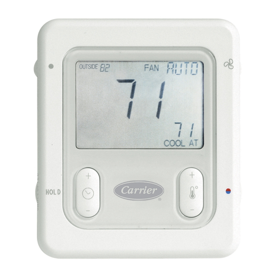
Fig. 1 - - Infinity Smart Sensor
Step 1 — Select Smart Sensor Location
Sensor should be mounted:
S Approximately 5 ft. (1.5m) from floor.
S Close to center of zone, preferably on inside partitioning wall.
S On section of wall without pipes or ductwork.
S Where wiring can be routed to it within wall. Avoid running
directly next to other AC power.
Sensor should NOT be mounted:
S Close to a window, on outside wall, or next to a door leading to
the outside.
S Exposed to direct light and heat from a lamp, sun, fireplace, or
other temperature radiating object which may cause a false
reading.
S Close to or in direct airflow from supply registers and return- -air
grilles.
S In areas with poor air circulation, such as behind a door or in an
alcove.
S Do not run wires next to AC power lines.
SYSTXCCSMS01- -A
INSTALLATION
A04147
Advertisement
Table of Contents

Related Manuals for Carrier SYSTXCCSMS01-A


Summary of Contents for Carrier SYSTXCCSMS01-A
-
Page 1: Installation Instructions
A04147 INTRODUCTION Fig. 1 - - Infinity Smart Sensor SYSTXCCSMS01- -A Carrier’s Infinityr Smart Sensors are optional replacements for Remote Room Sensors used with Infinityr Zoning systems. It INSTALLATION provides a temperature display and buttons to adjust the desired temperature within the zone. It also displays outdoor temperature Step 1 —... - Page 2 Fan Status Outside Temp / Indoor Humidity Fan Control Humidity/OAT Room Temperature Set point HOL D Hold/Unoccupied COOL / HEAT T emp (+/-) Time (+/-) A04136 Fig. 2 - - Smart Sensor Functions 6. Push any excess wire into the wall. Seal hole in wall to pre- Step 2 —...
- Page 3 button for 10 seconds to enter setup menu. Use the HOLD button timer or the default time will be replaced with “SCHEDULED,” to toggle between “LIGHT OFF” and “LIGHT ON” which will depending on the type of wall control, and the program resumes enable a fixed low intensity backlight.
- Page 4 Fig. 3 - - Typical Smart Sensor Wiring diagram Catalog No: ZONESMS---02SI Copyright 2012 Carrier Corp. S 7310 W. Morris St. S Indianapolis, IN 46231 Edition Date: 10/12 Manufacturer reserves the right to change, at any time, specifications and designs without notice and without obligations.
Need help?
Do you have a question about the SYSTXCCSMS01-A and is the answer not in the manual?
Questions and answers