Table of Contents
Advertisement
Quick Links
Advertisement
Table of Contents

Related Manuals for UfiSpace S9500-22XST


Summary of Contents for UfiSpace S9500-22XST
- Page 1 S9500-22XST Disaggregated Cell Site Gateway Hardware Installation Guide R1.1...
-
Page 2: Table Of Contents
Fan FRU LED ......................... 19 Management port LED ......................19 11 Initial System Setup ......................20 12 Cable Connections ......................22 Connecting the USB Extender Cable ..................22 Connecting a Cable to the ToD Interface................22 S9500-22XST Hardware Installation Guide | i... - Page 3 Connecting a Cable to the BITS Interface ................23 Connecting the GNSS Interface ................... 23 Connecting the 1PPS Interface .................... 24 Connecting the 10MHz Interface ..................24 Connecting the Transceiver ....................24 13 Cautions and Regulatory Compliance Statements .............. 26 S9500-22XST Hardware Installation Guide | ii...
-
Page 4: Overview
1 Overview The UfiSpace S9500-22XST is a high-performance, versatile open networking white box router that is designed to address the changing needs of backhaul transport requirements as Telecoms make the transition from legacy technologies towards 5G. It enables telecoms and service providers to deploy disaggregated open network infrastructure to lower costs and rapidly scale existing services for edge computing, mobile backhaul, and broadband access applications. -
Page 5: Preparation
PC with terminal emulation software. Refer to the "Initial System Setup" section for details. • Baud rate: 115200 bps • Data bits: 8 • Parity: None • Stop bits: 1 • Flow control: None S9500-22XST Hardware Installation Guide | 2... -
Page 6: Installation Environment Requirements
200 watts on each power circuit. • Space Clearance: The S9500-22XST width is 17.32 inches (44cm) and shipped with a rack mount brackets suitable for 19 inch (48.3cm) wide racks and adjustable mounting rails are provided for rack depths of 22 inches (55.9cm) to 33 inches (83.8cm). -
Page 7: Preparation Check List
• Cooling: The S9500-22XST airflow direction is front-to-back. Make sure the equipment on the same rack have the same airflow direction. Figure 3. Figure 4. Preparation Check List Task Check Date Power voltage and electric current requirement DC version: -36 to -75V DC, 8A maximum x2 or;... -
Page 8: Package Contents
AC Power Cord 0.91lb (414g)/2 pcs 72.05” (1830mm) 2 pcs (AC version only) (0.46lb (207g)/pcs) RJ45 to DB9 Female 95.98” (2438mm) 1 pcs 0.23lb (105g)/pcs Cable SMA to BNC Cable 11.81” (300mm) 2 pcs 0.02lb (10.5g)/pcs S9500-22XST Hardware Installation Guide | 5... -
Page 9: Component Physical Information
0.008lb (3.5g) Screw kit for rack mount bracket 0.02lb (7g) and adjustable mounting rail S9500-22XST (W x D x H) 17.32” x 11.89” x 1.71” (440 x 302 x 43.5mm) Dimension PSU (W x D x H) 1.99” x 8.31” x 1.58” (50.5 x 211 x 40.2mm) Fan (W x D x H) 2.03”... -
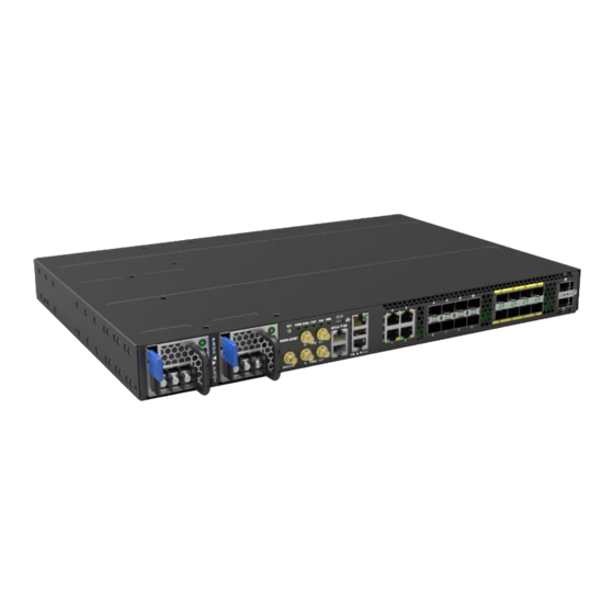
Page 10: Identifying Your System
4 Identifying Your System S9500-22XST Overview Figure 5. S9500-22XST Hardware Installation Guide | 7... -
Page 11: Dc Version Psu Overview
Power supply unit (PSU) with 1+1 redundancy. Hot swappable, field replaceable unit (FRU). Figure 6. AC Version PSU Overview Power supply unit (PSU) with 1+1 redundancy. Hot swappable, field replaceable unit (FRU). Figure 7. S9500-22XST Hardware Installation Guide | 8... -
Page 12: Fan Overview
Maximum Support Distance Support Speed 0 ~ 3 RJ45 238.01ft (100m) 100M/1G 4 ~ 11 SFP+ 49.7mi (80km) 1G/10G 12 ~ 19 SFP28 24.85mi (40km) 10/25G 20 ~ 21 QSFP28 24.85mi (40km) 40/100G Figure 9. S9500-22XST Hardware Installation Guide | 9... -
Page 13: Rack Mounting
M4.0*L6.5mm screws provided in the package. Then secure the adjustable mounting rail to the rack posts. (See Figure 12). Illustrations are for reference purposes only. Actual scenario may differ. Screws for rack posts not included. Figure 11. Figure 12. S9500-22XST Hardware Installation Guide | 10... -
Page 14: Installing Fan Modules
4. Carefully slide the new fan module into the fan bay and gently push until it is flush with the case. 5. Secure the captive screw on the fan module to lock the fan in place. Figure 15. S9500-22XST Hardware Installation Guide | 11... -
Page 15: Installing Power Supply Units
1. Locate the release tab on the PSU. Then press and hold down the release tab to unlock the PSU from the power bay. 2. While holding down the release tab, grip the PSU's handle and firmly pull it out of the power bay. DC Version: AC Version: Figure 17. S9500-22XST Hardware Installation Guide | 12... - Page 16 5. An audible click will be heard when the PSU is installed correctly. The PSU will not go in all the way if it is in the wrong direction. Illustrations are for reference purposes only. Actual scenario may differ. DC Version: AC Version: Figure 18. S9500-22XST Hardware Installation Guide | 13...
-
Page 17: Grounding The Router
3. Insert the exposed grounding wire all the way into the hole of the grounding lug (provided with package contents). 4. Using a crimping tool, firmly secure the grounding wire to the grounding lug. Figure 19. S9500-22XST Hardware Installation Guide | 14... - Page 18 6. Using 2 M4 screws and 4 washers (provided with the package contents), firmly lock the grounding lug to either of the designated grounding locations on the router. Figure 20. Figure 21. Figure 22. S9500-22XST Hardware Installation Guide | 15...
-
Page 19: Connecting Power
Also, please ensure that both PSUs have been properly installed before powering up the equipment, as the S9500-22XST is designed to support 1 + 1 power redundancy. 2. Attach the power cable. -
Page 20: Ac Version
Also, please ensure that both PSUs have been properly installed before powering up the equipment, as the S9500-22XST is designed to support 1 + 1 power redundancy. -
Page 21: Verifying System Operation
**Note: need NOS to activate this feature STAT System (X86 & BMC) no boot System boot complete (NOS) Solid Green **Note: need NOS to activate this feature Blinking Green System is booting Solid Yellow System boot complete(DIAG OS) S9500-22XST Hardware Installation Guide | 18... -
Page 22: Psu Fru Led
Management port LED LED Condition Equipment Status Left LED 1G no link Solid Green 1G link-up Blinking Green 1G TX/RX activity Right LED No activity Solid Amber 10M/100M link-up Blinking Amber 10M/100M TX/RX activity S9500-22XST Hardware Installation Guide | 19... -
Page 23: Initial System Setup
USB cable provided in the packaging contents. Download the suitable driver for your operating system (OS) using the URL below: • https://www.silabs.com/products/development-tools/software/usb-to-uart- bridge- vcp-drivers • https://www.silabs.com/ and search for CP210X Figure 28. S9500-22XST Hardware Installation Guide | 20... - Page 24 After the connection is established, a prompt for the username and password displays. Enter the username and password to access the CLI. The username and password should be provided by the Network Operating System (NOS) vendor. S9500-22XST Hardware Installation Guide | 21...
-
Page 25: Cable Connections
1. Connect one end of a straight-through Ethernet cable to the GNSS unit 2. Connect the other end of the straight-through Ethernet cable to the port marked “TOD” located on the front panel of the router. Figure 30. S9500-22XST Hardware Installation Guide | 22... -
Page 26: Connecting A Cable To The Bits Interface
3. Below is the pinout for the BITS port. Figure 32. Connecting the GNSS Interface Connect an external GNSS antenna with an impedance of 50 ohms to the port marked “GNSS ANT” located on the front panel of the router. Figure 33. S9500-22XST Hardware Installation Guide | 23... -
Page 27: Connecting The 1Pps Interface
It is recommended to use hook-and-loop style straps to secure and organize the cables. • For easier management, label each fiber-optic cable and record its respective connection. • Maintain a clear line of sight to the port LEDs by routing the cables away from the LEDs. S9500-22XST Hardware Installation Guide | 24... - Page 28 3. Place the bail (wire handle) in the unlocked position and align the transceiver with the port. 4. Slide the transceiver into the port and use gentle pressure to secure it in place. An audible click can be heard when the transceiver is secured in the port. S9500-22XST Hardware Installation Guide | 25...
-
Page 29: Cautions And Regulatory Compliance Statements
The equipment and its modules should only be repaired, maintained or replaced by skilled personnel. Instructed person is a term applied to persons who have been instructed and trained by a skilled person, or who is supervised by a skilled person. <電源コードセットに関する使用上の注意事項> 付属の「AC電源コードセット」は、本製品専用のものです。他の電気機器には絶 対に使用しないでください。 S9500-22XST Hardware Installation Guide | 26... - Page 30 この装置は、クラスA機器です。この装置を住宅環境で使用すると電波妨害を引き 起こすことがあります。この場合には使用者が適切な対策を講ずるよう要求される ことがあります。 S9500-22XST Hardware Installation Guide | 27...
- Page 31 www.ufispace.com...
Need help?
Do you have a question about the S9500-22XST and is the answer not in the manual?
Questions and answers