Table of Contents
Advertisement
Quick Links
Advertisement
Table of Contents

Related Manuals for UfiSpace S9502-16SMT


Summary of Contents for UfiSpace S9502-16SMT
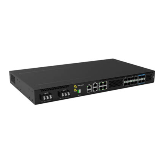
- Page 1 S9502-16SMT Disaggregated Cell Site Gateway Hardware Installation Guide R1.0...
-
Page 2: Table Of Contents
Package Contents ........................ 5 Accessory List ........................... 5 Component Physical Information .................... 6 Identifying Your System ....................... 7 S9502-16SMT DC Version Overview ..................7 S9502-16SMT AC Version Overview ..................8 DC Version PSU Overview ......................9 AC Version PSU Overview ......................9 Port Overview .......................... -
Page 3: Overview
The S9502-16SMT has a lightweight design without fans and fixed power supplies to reduce moving parts and enable longer lasting operations with minimal maintenance servicing. It... -
Page 4: Preparation
PC with terminal emulation software. Refer to the "Initial System Setup" section for details. • Baud rate: 115200 bps • Data bits: 8 • Parity: None • Stop bits: 1 • Flow control: None S9502-16SMT Hardware Installation Guide | 2... -
Page 5: Installation Environment Requirements
19 inch (48.3cm) wide racks. The rack mount brackets can be installed at the front or in the center of the S9502-16SMT. The depth of the S9502-16SMT chassis is 9.84 inches (25cm). The connectors for the power supplies and interfaces will extend outwards from the front panel by 0.55 inches (1.4cm). -
Page 6: Preparation Check List
• Cooling: The S9502-16SMT has a fanless design so the rack or cabinet must have a minimum of 3.28 feet/second (1 meter/second) airflow in any direction without recirculation. Figure 3. Figure 4. Preparation Check List Task Check Date Power voltage and electric current requirement DC version: -36V~ -75V DC, 4.5-2.5 ampere maximum or;... -
Page 7: Package Contents
Male to Female 7.87” (200mm) 1 pcs 0.021lbs (9.7g)/pcs 200mm 1.04lbs AC power cord (AC 72.05” (1830mm) 2 pcs (470g)/2 pcs version only) (0.52lbs (235g)/pcs) RJ45 to DB9 Female 94.49” (2400mm) 1 pcs 0.27lbs (123.9g)/pcs Cable S9502-16SMT Hardware Installation Guide | 5... -
Page 8: Component Physical Information
Screw kit for ground lug 0.008lbs (3.8g) per set Screw kit for rack mount bracket 0.01lbs (6.5g) per set 17.32” x 9.84” x 1.713” Dimension S9502-16SMT (W x D x H) (440 x 250 x 43.5mm) S9502-16SMT Hardware Installation Guide | 6... -
Page 9: Identifying Your System
4 Identifying Your System S9502-16SMT DC Version Overview Figure 5. Figure 6. S9502-16SMT Hardware Installation Guide | 7... -
Page 10: S9502-16Smt Ac Version Overview
S9502-16SMT AC Version Overview Figure 7. Figure 8. S9502-16SMT Hardware Installation Guide | 8... -
Page 11: Dc Version Psu Overview
Port Overview Port ID Form Factor Maximum Support Distance Support Speed 0 ~ 3 RJ45 238.01ft (100m) 100M/1GE 4 ~ 11 24.85mi (40km) 12 ~ 15 SFP+ 24.85mi (40km) 1GE/10GE DC Version: Figure 11. S9502-16SMT Hardware Installation Guide | 9... - Page 12 AC Version: Figure 12. S9502-16SMT Hardware Installation Guide | 10...
-
Page 13: Rack Mounting
(See Figure 14). For rack post widths wider than 19”, different brackets are available upon request (See Figure 15). Illustrations are for reference purposes only. Actual cabinet posts may differ. Figure 14. S9502-16SMT Hardware Installation Guide | 11... - Page 14 Figure 15. S9502-16SMT Hardware Installation Guide | 12...
-
Page 15: Grounding The Router
3. Insert the exposed grounding wire all the way into the hole of the grounding lug (provided with package contents). 4. Using a crimping tool, firmly secure the grounding wire to the grounding lug. Figure 16. S9502-16SMT Hardware Installation Guide | 13... - Page 16 6. Using 2 M4 screws and 4 washers (provided with the package contents), firmly lock the grounding lug to the designated grounding location on the router. Figure 17. Figure 18. Figure 19. S9502-16SMT Hardware Installation Guide | 14...
-
Page 17: Connecting Power
5. Verify that the power supply is operating. If connected correctly, when turned on, the system LED will light up with a Green color designating normal operation. S9502-16SMT Hardware Installation Guide | 15... -
Page 18: Ac Version
Plug the power cord into the AC PSU and secure it tightly. 3. Verify that the power supply is operating. If connected correctly, when turned on, the system LED will light up with a Green color designating normal operation. Figure 22. S9502-16SMT Hardware Installation Guide | 16... -
Page 19: Verifying System Operation
System timing synchronization fail. Blinking Yellow **Note: need NOS to activate this feature STAT System (X86 & BMC) no boot System boot complete Solid Green **Note: need NOS to activate this feature Blinking Green System is booting S9502-16SMT Hardware Installation Guide | 17... -
Page 20: Management Port Led
Management port LED Left LED Condition Equipment Status No link Green-solid Link-up at 1G Green-blinking TX/RX activity at 1G Right LED Condition Equipment Status No link Amber-solid Link-up at 10M/100M Amber-blinking TX/RX activity at 10M/100M S9502-16SMT Hardware Installation Guide | 18... -
Page 21: Initial System Setup
After the connection is established, a prompt for the username and password displays. Enter the username and password to access the CLI. The username and password should be provided by the Network Operating System (NOS) vendor. S9502-16SMT Hardware Installation Guide | 19... -
Page 22: Cable Connections
1. Connect one end of a straight-through Ethernet cable to the GNSS unit 2. Connect the other end of the straight-through Ethernet cable to the port marked “TOD” located on the front panel of the router. Figure 26. S9502-16SMT Hardware Installation Guide | 20... -
Page 23: Connecting The 1Pps Interface
It is recommended to use hook-and-loop style straps to secure and organize the cables. • For easier management, label each fiber-optic cable and record its respective connection. • Maintain a clear line of sight to the port LEDs by routing the cables away from the LEDs. S9502-16SMT Hardware Installation Guide | 21... - Page 24 3. Place the bail (wire handle) in the unlocked position and align the transceiver with the port. 4. Slide the transceiver into the port and use gentle pressure to secure it in place. An audible click can be heard when the transceiver is secured in the port. S9502-16SMT Hardware Installation Guide | 22...
-
Page 25: Cautions
The equipment and its modules should only be repaired, maintained or replaced by skilled personnel. Instructed person is a term applied to persons who have been instructed and trained by a skilled person, or who is supervised by a skilled person. S9502-16SMT Hardware Installation Guide | 23... - Page 26 Only afforded by the use of a tool or lock and key, or other means of security, and controlled by the authority responsible for the location. Suitable for installation in Information Technology Rooms in accordance with Article 645 of the National Electrical Code and NFPA 75. S9502-16SMT Hardware Installation Guide | 24...
- Page 27 www.ufispace.com...
Need help?
Do you have a question about the S9502-16SMT and is the answer not in the manual?
Questions and answers