Table of Contents
Advertisement
Quick Links
Advertisement
Table of Contents

Related Manuals for UfiSpace S9501-18SMT


Summary of Contents for UfiSpace S9501-18SMT
- Page 1 S9501-18SMT Disaggregated Cell Site Gateway Hardware Installation Guide R1.0...
-
Page 2: Table Of Contents
Grounding the Router ..............16 Connecting Power ............... 18 DC Version ....................18 AC Version ....................19 10 Verifying System Operation ............20 10.1 Front Panel LED ..................20 10.2 PSU FRU LED ....................21 10.3 Fan FRU LED ....................21 11 Initial System Setup ..............22 S9501-18SMT Hardware Installation Guide | i... - Page 3 12.2 Connecting a Cable to the ToD Interface ...........23 12.3 Connecting the GNSS Interface ..............23 12.4 Connecting the 1PPS Interface ..............24 12.5 Connecting the 10MHz Interface ...............24 12.6 Connecting the Transceiver................24 13 Cautions ..................25 S9501-18SMT Hardware Installation Guide | ii...
-
Page 4: Overview
1 Overview The UfiSpace S9501-18SMT is a high-performance, versatile open networking white box router that is designed to address the changing needs of backhaul transport requirements as Telecoms make the transition from legacy technologies towards 5G. It enables telecoms and service providers to deploy disaggregated open network infrastructure to lower costs and rapidly scale existing services for edge computing, mobile backhaul, and broadband access applications. -
Page 5: Preparation
PC with terminal emulation software. Refer to the "Initial System Setup" section for • details. • Baud rate: 115200 bps • Data bits: 8 • Parity: None • Stop bits: 1 • Flow control: None S9501-18SMT Hardware Installation Guide | 2... -
Page 6: Installation Environment Requirements
(2.54cm) and the handle for the power supplies will extend outwards by 1.5 inches (3.81cm). Therefore, to accomodate the fan and power supply handles, a minimum space clearance of 2 inches(5.08cm) is needed at the front and back of the S9501-18SMT. A total minimum reserve depth of 16 inches (40.6cm) is required. -
Page 7: Preparation Check List
Cooling: The S9501-18SMT airflow direction is front-to-back. Make sure the equipment • on the same rack have the same airflow direction. Figure 3. Top DUT AIR FLOW Bo om DUT Rear wall clearance = 2.0” Figure 4. Preparation Check List Task Check Date Power voltage and electric current requirement DC version: -48V DC, 8-4 ampere maximum or;... -
Page 8: Package Contents
(406.8 x 43 x 21mm) Screw Kit 8 x Screws M4.0*L6.5mm 8 sets 0.01lbs (6.5g)/set (for Adjustable Mounting Rail) Cable USB 2.0 A Type Male to Female 7.87” (200mm) 1 pcs 0.021lbs (9.7g)/pcs 200 mm S9501-18SMT Hardware Installation Guide | 5... -
Page 9: Component Physical Information
0.1lbs (6.5g) per set mounting rail 17.32” x 11.89” x 1.713” S9501-18SMT (W x D x H) (440 x 302 x 43.5mm) Dimension PSU (W x D x H) 1.99” x 8.31” x 1.58” (50.5 x 211 x 40.2mm) Fan (W x D x H) 1.57”... -
Page 10: Identifying Your System
4 Identifying Your System S9501-18SMT DC Version Overview D = 11.89” (302 mm) W= 17.32” (440 mm) H = 1.713” (43.5 mm, 1RU) Figure 5. S9501-18SMT Hardware Installation Guide | 7... -
Page 11: S9501-18Smt Ac Version Overview
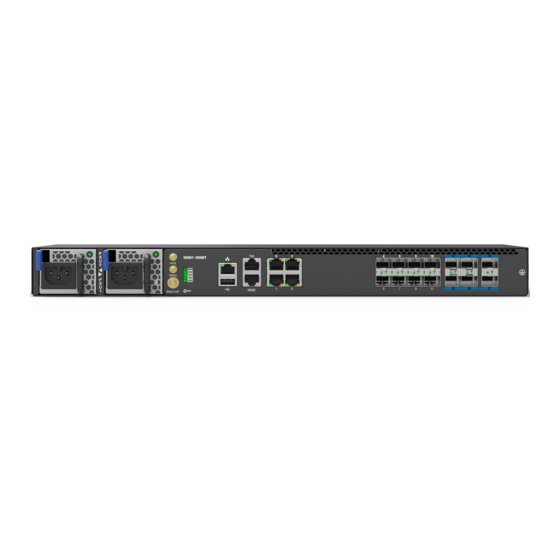
DC PSU 1 GNSS Rese t Grounding Lug Console 3 x 4028 Fan Modules Figure 6. S9501-18SMT AC Version Overview D = 11.89” (302 mm) W= 17.32” (440 mm) H = 1.713” (43.5 mm, 1RU) Figure 7. S9501-18SMT Hardware Installation Guide | 8... -
Page 12: Dc Version Psu Overview
Figure 8. DC Version PSU Overview 1+1, hot swappable power supply unit (PSU) field replaceable unit (FRU). Figure 9. Latch Color: Blue 198.5 AIR FLOW SPEC LABEL CUS BAR CODE 40.2 EMI Shielding Gaskets (3x) Handle Color: Black Figure 10. S9501-18SMT Hardware Installation Guide | 9... -
Page 13: Ac Version Psu Overview
AC Version PSU Overview 1+1, hot swappable power supply unit (PSU) field replaceable unit (FRU). Figure 11. Figure 12. Fan Overview 2+1, hot swappable fan field replaceable unit (FRU). Figure 13. S9501-18SMT Hardware Installation Guide | 10... -
Page 14: Port Overview
Port Overview Port ID Form Factor Maximum Support Distance Support Speed 0 ~ 3 RJ45 238.01ft (100m) 1GE/100M 4 ~ 11 2.5GE/1GE/100M 24.85mi (40km) 12 ~ 17 10GE/2.5GE/1GE SFP+ 24.85mi (40km) DC Version: Figure 14. AC Version: Figure 15. S9501-18SMT Hardware Installation Guide | 11... -
Page 15: Rack Mounting
M4.0*L6.5mm screws provided in the package. Then secure the adjustable mounting rail to the rack posts using the screws and cage nuts provided. (See Figure 18) Illustrations are for reference purposes only. Actual cabinet posts may differ. Note Figure 17. Figure 18. S9501-18SMT Hardware Installation Guide | 12... -
Page 16: Installing Fan Modules
4. Carefully slide the new fan module into the fan bay and gently push until it is flush with the case. 5. Secure the captive screw on the fan module to lock the fan in place. FA N FA N Figure 21. S9501-18SMT Hardware Installation Guide | 13... -
Page 17: Installing Power Supply Units
1. Locate the release tab on the PSU. Then press and hold down the release tab to unlock the PSU from the power bay. 2. While holding down the release tab, grip the PSU's handle and firmly pull it out of the power bay. DC Version: AC Version: Figure 23. S9501-18SMT Hardware Installation Guide | 14... - Page 18 5. An audible click will be heard when the PSU is installed correctly. The PSU will not go in all the way if it is in the wrong direction. The PSUs must have the same airflow direction as the installed fans (front to back). Note DC Version: AC Version: S9501-18SMT Hardware Installation Guide | 15...
-
Page 19: Grounding The Router
3. Insert the exposed grounding wire all the way into the hole of the grounding lug (provided with package contents). 4. Using a crimping tool, firmly secure the grounding wire to the grounding lug. Green/Yellow 24. S9501-18SMT Hardware Installation Guide | 16... - Page 20 4 x M4 Lock Washers 2 x M4*L8.0 mm Screw Figure 26. Loca on-1 Loca on-2 Star Washers (4 pcs) Grounding Lug Installed with Screw (2 pcs) & Ground Screw (2 pcs) Star Washers (4 pcs) Figure 27. S9501-18SMT Hardware Installation Guide | 17...
-
Page 21: Connecting Power
5. Verify that the power supply is operating. If connected correctly, when turned on, the LED on the PSU will light up with a Green color designating normal operation. S9501-18SMT Hardware Installation Guide | 18... -
Page 22: Ac Version
Plug the power cord into the AC PSU and secure it tightly. 3. Verify that the power supply is operating. If connected correctly, when turned on, the LED on the PSU will light up with a Green color designating normal operation. Figure 30. S9501-18SMT Hardware Installation Guide | 19... -
Page 23: Verifying System Operation
System timing core(1588 and SyncE) is synchronized to external timing source (ex: GNSS, 1PPS, PTP, etc). Solid Green NOTE: Need NOS to activate this feature. System is synchronized in SyncE mode. Blinking Green NOTE: Need NOS to activate this feature. S9501-18SMT Hardware Installation Guide | 20... -
Page 24: Psu Fru Led
Equipment Status Main board 3.3V power fail or Fan is not present. Solid Green Fan is present and interrupt de-assert. Blinking Green N/A. Solid Amber N/A. Blinking Amber Fan is present but interrupt assert. S9501-18SMT Hardware Installation Guide | 21... -
Page 25: Initial System Setup
After the connection is established, a prompt for the username and password displays. Enter the username and password to access the CLI. The username and password should be provided by the Network Operating System (NOS) vendor. S9501-18SMT Hardware Installation Guide | 22... -
Page 26: Cable Connections
“TOD” located on the front panel of the router. 12.3 Connecting the GNSS Interface Connect an external GNSS antenna with an impedance of 50 ohms to the port marked “GNSS ANT” located on the front panel of the router. S9501-18SMT Hardware Installation Guide | 23... -
Page 27: Connecting The 1Pps Interface
3. Place the bail (wire handle) in the unlocked position and align the transceiver with the port. 4. Slide the transceiver into the port and use gentle pressure to secure it in place. An audible click can be heard when the transceiver is secured in the port. S9501-18SMT Hardware Installation Guide | 24... -
Page 28: Cautions
The equipment and its modules should only be repaired, maintained or replaced by skilled personnel. Instructed person is a term applied to persons who have been instructed and trained by a skilled person, or who is supervised by a skilled person. S9501-18SMT Hardware Installation Guide | 25... - Page 29 www.ufispace.com...
Need help?
Do you have a question about the S9501-18SMT and is the answer not in the manual?
Questions and answers