Table of Contents
Advertisement
Quick Links
Advertisement
Table of Contents

Related Manuals for UfiSpace S9510-30XC


Summary of Contents for UfiSpace S9510-30XC
- Page 1 S9510-30XC Disaggregated Cell Site Gateway Hardware Installation Guide R1.0...
-
Page 2: Table Of Contents
Package Contents ........................ 7 Accessory List ........................... 7 Component Physical Information .................... 8 Identifying Your System ....................... 9 S9510-30XC DC Version Overview ................... 9 S9510-30XC AC Version Overview ..................10 DC Version PSU Overview ...................... 11 AC Version PSU Overview ...................... 11 Fan Overview ......................... -
Page 3: Overview
The S9510-30XC is future-proofed with a powerful 4-core processor, 10GE/ 25G/ 40GE/ 100GE high-speed interfaces, and full timing features supporting IEEE 1588v2 and SyncE, which enables service providers to easily migrate from 2G, 3G, 4G BBUs to 5G RAN. -
Page 4: Preparation
PC with terminal emulation software. Refer to the "Initial System Setup" section for details. • Baud rate: 115200 bps • Data bits: 8 • Parity: None • Stop bits: 1 • Flow control: None S9510-30XC Hardware Installation Guide | 3... -
Page 5: Installation Environment Requirements
1 inches (2.5cm) is needed at the back of the S9510- 30XC. To accommodate the power supply handles, cabling and airflow, a minimum space clearance of 6 inches (15.2cm) is needed at the front of the S9510-30XC. A total minimum reserve depth of 18.89 inches (47.9cm) is required. - Page 6 Figure 2. • Cooling: The S9510-30XC airflow direction is front-to-back. Make sure the equipment on the same rack have the same airflow direction. Figure 3. Figure 4. S9510-30XC Hardware Installation Guide | 5...
-
Page 7: Preparation Check List
19” (48.3cm), and a depth of 18.89 inches (47.9cm) Thermal requirement S9510-30XC working temperature is -40 to 65°C (-40°F to 140°F), airflow direction is front-to-back Installation tools required #2 Philips Screwdriver, 6-AWG wire stripper, and crimping tool... -
Page 8: Package Contents
1 pcs 0.021lbs (9.7g)/pcs Type Male to Female 1.04lbs (470g)/2 pcs AC power cord 72.05” (1830mm) 2 pcs (AC version only) (0.52lbs (235g)/pcs) RJ45 to DB9 Female 94.49” (2438mm) 1 pcs 0.23lbs (105g)/pcs Cable S9510-30XC Hardware Installation Guide | 7... -
Page 9: Component Physical Information
Screw kit for rack mount bracket and adjustable 0.1lbs (6.5g) per set mounting rail S9510-30XC (W x D x H) 17.32” x 11.89” x 1.713” (440 x 302 x 43.5mm) Dimension PSU (W x D x H) 1.99” x 8.31” x 1.58” (50.5 x 211 x 40.2mm) Fan (W x D x H) 1.57”... -
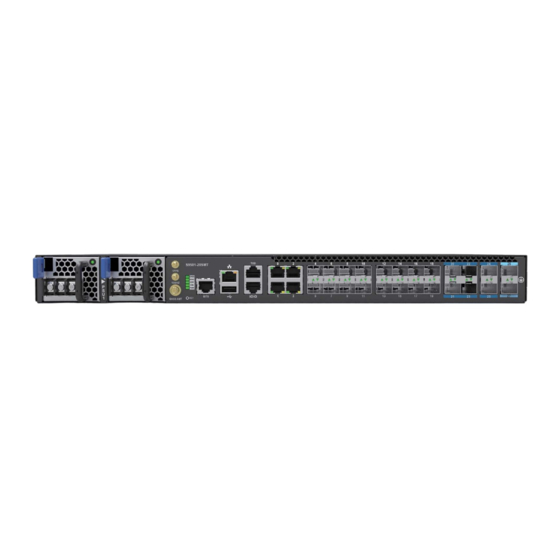
Page 10: Identifying Your System
4 Identifying Your System S9510-30XC DC Version Overview Figure 5. Figure 6. S9510-30XC Hardware Installation Guide | 9... -
Page 11: S9510-30Xc Ac Version Overview
S9510-30XC AC Version Overview Figure 7. Figure 8. S9510-30XC Hardware Installation Guide | 10... -
Page 12: Dc Version Psu Overview
DC Version PSU Overview 1+1, hot swappable power supply unit (PSU) field replaceable unit (FRU). Figure 9. Figure 10. AC Version PSU Overview 1+1, hot swappable power supply unit (PSU) field replaceable unit (FRU). Figure 11. S9510-30XC Hardware Installation Guide | 11... -
Page 13: Fan Overview
4+1, hot swappable fan field replaceable unit (FRU). Figure 13. Port Overview Port ID Form Factor Maximum Support Distance Support Speed 0 ~ 1 QSFP28 24.85mi (40km) 100GE 2 ~ 29 SFP28 24.85mi (40km) 25GE DC Version: S9510-30XC Hardware Installation Guide | 12... - Page 14 Figure 14. AC Version: Figure 15. S9510-30XC Hardware Installation Guide | 13...
-
Page 15: Rack Mounting
M4.0*L6.5mm screws provided in the package. Then secure the adjustable mounting rail to the rack posts using the screws and cage nuts provided (See Figure 18). Illustrations are for reference purposes only. Actual cabinet posts may differ. Figure 17. Figure 18. S9510-30XC Hardware Installation Guide | 14... -
Page 16: Installing Fan Modules
4. Carefully slide the new fan module into the fan bay and gently push until it is flush with the case. 5. Secure the captive screw on the fan module to lock the fan in place. Figure 21. S9510-30XC Hardware Installation Guide | 15... -
Page 17: Installing Power Supply Units
1. Locate the release tab on the PSU. Then press and hold down the release tab to unlock the PSU from the power bay. 2. While holding down the release tab, grip the PSU's handle and firmly pull it out of the power bay. DC Version: AC Version: Figure 23. S9510-30XC Hardware Installation Guide | 16... - Page 18 5. An audible click will be heard when the PSU is installed correctly. The PSU will not go in all the way if it is in the wrong direction. Illustrations are for reference purposes only. Actual cabinet posts may differ. DC Version Figure 24. AC Version Figure 25. S9510-30XC Hardware Installation Guide | 17...
-
Page 19: Grounding The Router
3. Insert the exposed grounding wire all the way into the hole of the grounding lug (provided with package contents). 4. Using a crimping tool, firmly secure the grounding wire to the grounding lug. Figure 26. S9510-30XC Hardware Installation Guide | 18... - Page 20 6. Using 2 M4 screws and 4 washers (provided with the package contents), firmly lock the grounding lug to either of the designated grounding locations on the router. Figure 27. Figure 28. Figure 29. S9510-30XC Hardware Installation Guide | 19...
-
Page 21: Connecting Power
Tighten the screws to a torque value of 6.94lbf.in (+/-10%). If the torque is not enough, the lug will not be secure and may cause malfunctions. If the torque is too much, the terminal block or lug may be damaged. Figure 31. S9510-30XC Hardware Installation Guide | 20... -
Page 22: Ac Version
Plug the power cord into the AC PSU and secure it tightly. 3. Verify that the power supply is operating. If connected correctly, when turned on, the LED on the PSU will light up with a Green color designating normal operation. Figure 32. S9510-30XC Hardware Installation Guide | 21... -
Page 23: Verifying System Operation
System timing synchronization fail. Blinking Yellow **Note: need NOS to activate this feature STAT System (X86 & BMC) no boot System boot complete Solid Green **Note: need NOS to activate this feature Blinking Green System is booting S9510-30XC Hardware Installation Guide | 22... -
Page 24: Psu Fru Led
Management port LED LED Condition Equipment Status Left LED 1G no link Solid Green 1G link-up Blinking Green 1G TX/RX activity Right LED No activity Solid Amber 10M/100M link-up Blinking Amber 10M/100M TX/RX activity S9510-30XC Hardware Installation Guide | 23... -
Page 25: Initial System Setup
After the connection is established, a prompt for the username and password displays. Enter the username and password to access the CLI. The username and password should be provided by the Network Operating System (NOS) vendor. S9510-30XC Hardware Installation Guide | 24... -
Page 26: Cable Connections
1. Connect one end of a straight-through Ethernet cable to the GNSS unit 2. Connect the other end of the straight-through Ethernet cable to the port marked “TOD” located on the front panel of the router. Figure 36. S9510-30XC Hardware Installation Guide | 25... -
Page 27: Connecting A Cable To The Bits Interface
Figure 37. Connecting the GNSS Interface Connect an external GNSS antenna with an impedance of 50 ohms to the port marked “GNSS ANT” located on the front panel of the router. Figure 38. S9510-30XC Hardware Installation Guide | 26... -
Page 28: Connecting The 1Pps Interface
Connect an external 1PPS cable with an impedance of 50 ohms to the port labelled “ 1PPS”. Figure 39. Connecting the 10MHz Interface Connect an external 10MHz cable with an impedance of 50 ohms to the port labelled "10MHz”. Figure 40. S9510-30XC Hardware Installation Guide | 27... -
Page 29: Connecting The Transceiver
3. Place the bail (wire handle) in the unlocked position and align the transceiver with the port. 4. Slide the transceiver into the port and use gentle pressure to secure it in place. An audible click can be heard when the transceiver is secured in the port. S9510-30XC Hardware Installation Guide | 28... -
Page 30: Cautions
The equipment and its modules should only be repaired, maintained or replaced by skilled personnel. Instructed person is a term applied to persons who have been instructed and trained by a skilled person, or who is supervised by a skilled person. S9510-30XC Hardware Installation Guide | 29... - Page 31 www.ufispace.com...
Need help?
Do you have a question about the S9510-30XC and is the answer not in the manual?
Questions and answers