Advertisement
Outdoor LoRa Gateway
Installation Quick Guide
This is a quick reference guide for
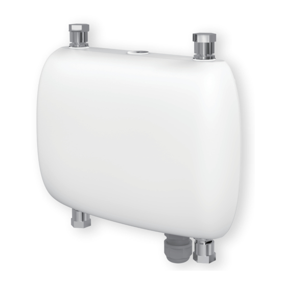
u Space Outdoor LoRa Gateway installation. This gateway
is designed for outdoor wall or pole mount installations.
1
Contents of delivery
2
Preparing the Installation
Connectors and Interfaces
3
Installation
Wall Mount
Pole Mount
Install Surge Protection Cable
Install 8 dBi Antenna
4
Optional Accessories Recommended
5
Cabling
6
Network Access
7
Model List
8
Appendix A
Declarations of Conformity and
Regulatory Information
All product speci cations are subject to change without notice
Advertisement
Table of Contents

Related Manuals for UfiSpace T77I868.00


Summary of Contents for UfiSpace T77I868.00
- Page 1 Outdoor LoRa Gateway Installation Quick Guide This is a quick reference guide for u Space Outdoor LoRa Gateway installation. This gateway is designed for outdoor wall or pole mount installations. Contents of delivery Optional Accessories Recommended Cabling Preparing the Installation Network Access Connectors and Interfaces Model List...
-
Page 2: Contents Of Delivery
This Outdoor LoRa Gateway is designed with Semtech Technology to provide low power and wide area (LPWA) unlicensed band wireless connection. This gateway supports connectivity for wide range of Internet of Things (IOT) applications. 1 Contents of Delivery Items x Outdoor LoRa Gateway with water protection cap on N-Type connector ports Metal Caps: V2.1 HW (3 for LTE version, 2 for non-LTE version);... -
Page 3: Preparing The Installation
2 Preparing the Installation Connectors and Interfaces V2.1 Gateway LoRa Antenna #1 (main) LoRa Antenna #2 (secondary, optional) 37.2 GPS Antenna LTE Antenna 48 VDC-IN/ PoE Pressure Vent V1.5 Gateway LoRa Antenna LTE Antenna (optional) 35.44 LTE Antenna 48 VDC-IN/ PoE Pressure Vent Caution Must make sure all antennas are installed properly before apply PoE power to the gateway. -
Page 4: Installation
3 Installation Wall Mount Our mounting bracket is designed for both wall and pole mount. Mounting bracket to walls Using expansion nail for wall mount Install Expansion Nail for Mounting Bracket Drill 4 holes on the designated wall. Locking the expansion nail for bracket. (Maximum 40Kg.cm torque for M5 nuts) After locking eache nut, reverse 3~4 turns on wall. -
Page 5: Pole Mount
Pole Mount V2.1 Gateway V1.5 Gateway All product speci cations are subject to change without notice - 5 -... - Page 6 Vertical and Horizontal Mount Install Hose Clamp Upright pole Upright direction clamp hole Minimum OD 35mm Horizontal direction clamp through hole Maximum OD 110mm Horizontal pole Maximum OD 120mm Minimum OD 40mm Maximum 55Kg.cm torque for hose clamp Connecting Earth Ground to Unit Warning The equipment has a separate protective earthing terminal on the chassis that must be permanently connected to earth ground to adequately ground the chassis and protect the operator from electrical hazards.
- Page 7 Install Surge Protection Cable ø 7.50 Screw M5, Length 12mm Surge Protection Cable V2.1 Gateway Surge Protection Cable must be properly connected to gateway housing and earth ground. Install the LoRa Antenna LoRa Antenna Screw nut Spring washer Flat washer Antenna port water leakage enhancement Antenna M6 Utype screw...
- Page 8 Install GPS Antenna 2 screws 2 screws 4 Optional Accessories Recommended Items LoRa 3, 5, 6, 7, 8 or 9 dBi antenna LoRa 0 dBi antenna (optional, for direct connecting to Gateway N-Type connector application, without antenna extension cable) LoRa 3 dBi antenna (optional, for direct connecting to Gateway N-Type connector application, without antenna extension cable) PoE Adapter (60 Watts) LoRa LoRa...
- Page 9 5 Cabling LoRa Antenna #1 LoRa Antenna #2 (optional) LTE Antenna GPS Antenna 3.3VDC output PoE Adapter for supporting 3 . 3 V A c t i v e GPS Antenna V2.1 Gateway LoRa Antenna #1 LTE Antenna PoE Adapter V1.5 Gateway All product speci cations are subject to change without notice - 9 -...
-
Page 10: Network Access
Caution Must make sure all antennas are installed properly before apply PoE power to the gateway. For un-connected N-Type Antenna Port, MUST install a " N-Type Water Protection Cap" to prevent water leaking into the device. " N-Type Water Protection Caps" are supplied with the gateway. - Page 11 Changing Con guration If default con guration does not t the usage in installation environment, please use setup showed in following photo to change con guration. You will need a Router that have DHCP server to o er IP to Outdoor LoRa Gateway, or use a switch/ hub and running a DHCP server on PC for the same purpose.
- Page 12 WAN Page This page describes the backhaul con guration. There are three kinds of backhaul which are Ethernet over PoE, WiFi client mode and LTE (if both LTE module and SIM card are installed) and can be selected and con gured through their own settings. Unsafe All product speci cations are subject to change without notice - 12 -...
-
Page 13: Model List
7 Model List Base Unit Ordering Information Model # Description T77I868.00 EU: Outdoor LoRa V2.1 Gateway, 863 - 870 MHz with LTE T77I868.01 EU: Outdoor LoRa V2.1 Gateway, 863 - 870 MHz without LTE GML820U-915U USA: Outdoor LoRa V2.1 Gateway, 902 - 928 MHz with LTE GME820K-920U S. -
Page 14: Declarations Of Conformity And Regulatory Information
8 Appendix A Declarations of Conformity and Regulatory Information FCC (GML820U-915U) Safety Information Follow the guidelines in this section to ensure proper operation and safe use of the u Space LoRa V2.1 Outdoor Gateway. Federal Communication Commission Interference Statement This device complies with Part 15 of the FCC Rules. Operation is subject to the following two conditions: (1) This device may not cause harmful interference, and (2) this device must accept any interference received, including interference that may cause undesired operation.
Need help?
Do you have a question about the T77I868.00 and is the answer not in the manual?
Questions and answers