Table of Contents
Advertisement
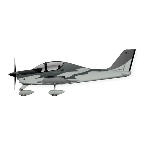
TECNAM P – MENTOR
M
ANUFACTURER
A
IRCRAFT MODEL
S
ERIAL NUMBER
: ...............................................
B
UILD YEAR
R
EGISTRATION MARKINGS
This manual must be carried in the airplane at all times.
The airplane has to be operated in compliance with procedures and limitations
contained herein.
Costruzioni Aeronautiche TECNAM S.p.A.
Via Maiorise
CAPUA (CE) – Italy
Tel. +39 0823 99.75.38
WEB:
www.tecnam.com
Thisdocument and the information thereon is the property of Costruzioni Aeronautiche Tecnam S.p.A., and may only be used
for the purpose for which Tecnam products are supplied, and/or use and maintenance of Tecnam Aircraft.
Reproduction or use of the data, information, drawings thereon, in whole or in part, is strictly Prohibited without
the express written permission of Costruzioni Aeronautiche Tecnam S.p.A.
P-Mentor – Aircraft Flight Manual
Aircraft Flight Manual
Doc. No. 2002/1032
Ed.1 Rev.7
2023, January 09
: COSTRUZIONI AERONAUTICHE TECNAM
: P-MENTOR
:.....................................
: ........................
S.p.A.
Advertisement
Table of Contents

Subscribe to Our Youtube Channel
Related Manuals for Tecnam P-Mentor


Summary of Contents for Tecnam P-Mentor
- Page 1 WEB: www.tecnam.com Thisdocument and the information thereon is the property of Costruzioni Aeronautiche Tecnam S.p.A., and may only be used for the purpose for which Tecnam products are supplied, and/or use and maintenance of Tecnam Aircraft. Reproduction or use of the data, information, drawings thereon, in whole or in part, is strictly Prohibited without...
- Page 3 P-Mentor – Aircraft Flight Manual Page i INDEX FOREWORD .....................III SECTIONS LIST ..................IV RECORD OF REVISIONS ..............ROR-1 LIST OF EFFECTIVE PAGES ............LOEP-2 Edition - Rev. 0 Aircraft Flight Manual INDEX...
- Page 4 P-Mentor – Aircraft Flight Manual Page ii Intentionally left blank Edition - Rev. 0 Aircraft Flight Manual INDEX...
- Page 5 P-Mentor – Aircraft Flight Manual Page iii FOREWORD Before using the airplane, you are recommended to read carefully this manual: a deep knowledge of airplane features and limitations will allow you for operating the airplane safely. For further information, please contact: COSTRUZIONI AERONAUTICHE TECNAM S.p.A.
-
Page 6: Section List
P-Mentor – Aircraft Flight Manual Page iv SECTIONS LIST General Section 1 Limitations(*) Section 2 Emergency Procedures Section 3 Normal Procedures Section 4 Performances Section 5 Weight and Balance Section 6 Airframe and Systems description Section 7 Airplane Care and Maintenance... -
Page 7: Record Of Revisions
P-Mentor– Aircraft Flight Manual Page RoR-1 RECORD OF REVISIONS Any revision to the present Manual, except actual weighing data, is recorded: a Record of Revisions is provided at the front of this manual and the operator is advised to make sure that the record is kept up-to-date. - Page 8 P-Mentor– Aircraft Flight Manual Page RoR-2 Ed / Description of Revised pages Approval Revision Ed. 1 First issue Rev. 0 Updates for: RoR-2 - Equipment list LoEP-1,2 - MOD 2002/235 3-5, 20, 22, 23, 28, Approved under the 32, 33, 40, 41 - MOD 2002/236 Ed.
- Page 9 P-Mentor– Aircraft Flight Manual Page RoR-3 Ed / Description of Revised pages Approval Revision RoR-3 Updates for: LoEP-1, 2, 3 - MOD 2002/239 Approved under the 2-1, 2, 15 thru 26 - MOD 2002/256 Ed. 1 authority of DOA ref.
- Page 10 P-Mentor– Aircraft Flight Manual Page RoR-4 Intentionally left blank Edition - Rev. 4 Aircraft Flight Manual LIST OF EFFECTIVE PAGES...
- Page 11 P-Mentor – Aircraft Flight Manual Page LoEP-1 LIST OF EFFECTIVE PAGES The List of Effective Pages (LOEP), applicable to manuals of every operator, lists all the basic AFM pages: each manual could contain either basic pages or one variant of these pages when the pages of some Supplements are embodied.
- Page 12 P-Mentor – Aircraft Flight Manual Page LoEP-2 Section Pages Revision i, ii, iii, iv, RoR-1 Rev. 0 RoR-2 Rev.3 Section 0 RoR-4 Rev.4 RoR-3, LoEP-1 thru 4 Rev.7 Rev. 0 0 thru 14 Section 1 15 thru 18 Rev. 2 0, 3 thru 9, 11 thru 14 Rev.
- Page 13 P-Mentor – Aircraft Flight Manual Page LoEP-4 Rev. 0 0 thru 8, 11, 12, 13, 16, 21, 22 Section 4 Rev. 1 15, 20 9, 10, 14, 17 thru 19 Rev. 7 Section 5 Rev. 0 Rev. 0 0 thru 3, 6 thru 12 4, 5, 16 Rev.
- Page 14 P-Mentor – Aircraft Flight Manual Page LoEP-4 0 thru 4, 6 Rev. 0 Section 9 Rev.7 Edition - Rev.7 Aircraft Flight Manual LIST OF EFFECTIVE PAGES...
- Page 15 P-Mentor – Aircraft Flight Manual Page 1 - 0 SECTION 1 GENERAL Edition - Rev. 0 Section 1 - GENERAL...
- Page 17 P-Mentor – Aircraft Flight Manual Page 1 - 1 INDEX INTRODUCTION ...................3 WARNING – CAUTION – NOTE ............3 THREE VIEW AND DIMENSIONS ............4 3.1. Dimensions ..................5 ENGINE ....................6 PROPELLER ..................6 GOVERNOR ..................6 MAXIMUM WEIGHTS AND SPECIFIC LOADINGS .......7 7.1. Maximum Weights ................7 7.2.
- Page 18 P-Mentor – Aircraft Flight Manual Page 1 - 2 Intentionally left blank Edition - Rev. 0 Section 1 – GENERAL INDEX...
-
Page 19: Section 1 - General Introduction
P-Mentor – Aircraft Flight Manual Page 1 - 3 Introduction The Aircraft Flight Manual has been prepared to provide pilots and instructors with information for the safe and efficient operation of this aeroplane. This manual also contains supplemental data supplied by the aeroplane manufacturer. - Page 20 P-Mentor – Aircraft Flight Manual Page 1 - 4 Three view and Dimensions Figure 1-1 - General View Edition - Rev. 0 Section 1 – GENERAL THREE VIEW AND DIMENSIONS...
- Page 21 P-Mentor – Aircraft Flight Manual Page 1 - 5 3.1. Dimensions Overall dimensions Wing Span…………………………………… 9.00 m / 29.5 ft Overall Length………………………………. 6.74 m / 22.1 ft Overall Height……………………………….. 2.50 m / 8.2 ft Stabilator span……………………………… 2.90m / 9.5 ft Wing Wing surface…………………………………...
- Page 22 P-Mentor – Aircraft Flight Manual Page 1 - 6 Engine Manufacturer .…………………….………..Bombardier- Rotax GmbH Model ……….………………………..……. 912 iSc 3 Sport Type Certificate .…………………..……..EASA.E.121 Engine type .…...………….………………… 4 cylinder horizontally-opposed twins with overall displacement of 1352 c.c., mixed cooling, (water-cooled...
- Page 23 P-Mentor – Aircraft Flight Manual Page 1 - 7 Maximum Weights and Specific Loadings 7.1. Maximum Weights Maximum Take-Off Weight…………... 720 kg (1587 lb) Maximum Landing Weight…………... 720 kg (1587 lb) 7.2. Specific Loadings Wing Loading…………......60.50 kg/m2 (12.39 lb/ft2) Power Loading…………......
- Page 24 P-Mentor – Aircraft Flight Manual Page 1 - 8 Fuel, Lubricant and Coolant 8.1. Fuel Fuel Specification..........MOGAS (ASTM D4814) MOGAS EN 228 Super/Super Plus (min RON 95) AVGAS 100LL (ASTM D910) 8.2. Lubricant Engine Oil Specification........Use only oil with RON424 classification 8.3.
- Page 25 P-Mentor – Aircraft Flight Manual Page 1 - 9 Acronyms and Terminology 9.1. Velocity terminology KCAS Calibrated Airspeed is the indicated airspeed expressed in knots, corrected taking into account the errors related to the instrument itself and its installation. KIAS Indicated Airspeed is the speed shown on the airspeed indicator and it is expressed in knots.
- Page 26 P-Mentor – Aircraft Flight Manual Page 1 - 10 9.2. Meteorological terminology International Standard Atmosphere: is the air atmospheric standard condition at sea level, at 15°C (59°F) and at 1013.25hPa (29.92 inHg). Official atmospheric pressure at airport level: it indicates the aircraft absolute altitude with respect to the official airport level.
- Page 27 P-Mentor – Aircraft Flight Manual Page 1 - 11 9.5. Aircraft performance and flight planning terminology Crosswind Velocity is the velocity of the crosswind component for the which adequate control of the airplane during take-off and landing is assured. is the total fuel minus unusable fuel.
- Page 28 P-Mentor – Aircraft Flight Manual Page 1 - 12 9.6. Weight and balance terminology Datum “Reference datum” is an imaginary vertical plane from which all horizontal distances are measured for balance purposes. is the horizontal distance of an item measured from the reference datum.
- Page 29 P-Mentor – Aircraft Flight Manual Page 1 - 13 10. Unit Conversion Chart Table 1-1 - Unit Conversion Chart MOLTIPLYING YIELDS EMPERATURE Fahrenheit [°F] Celsius [°C] ⋅ − Celsius [°C] Fahrenheit [°F] + ⋅ ...
- Page 30 P-Mentor – Aircraft Flight Manual Page 1 - 14 11. Litres / US Gallons Conversion Chart Table 1-2 - Litres/US Gallons Conversion Chart Litres US Gallons US Gallons Litres 11.4 15.1 22.7 30.3 37.9 10.6 45.4 11.9 53.0 13.2 60.6 15.9...
- Page 31 P-Mentor – Aircraft Flight Manual Page 1 - 15 12. DESIGNATION OF CIRCUIT BREAKERS Table 1-3 - Main breakers Breaker ID Definition START POWER Start power BATTERY Main bus ESSENTIAL BATTERY Essential bus BCK BATTERY Backup battery ALTERN Main bus...
-
Page 32: Audio Panel
P-Mentor – Aircraft Flight Manual Page 1 - 16 Table 1-4 – Main bus breakers Breaker ID Definition AUDIO PANEL Audio panel XPDR Transponder TAXI LIGHT Taxi light STDBY INSTR Stand-by instrument NAV LIGHT Navigation light CABIN HEAT Cabin heat INT. -
Page 33: Pitot Heat
P-Mentor – Aircraft Flight Manual Page 1 - 17 Table 1-5 - Essential bus breakers Breaker ID Definition PITOT HEAT Pitot heat Display unit PFD Engine interface system COM1 COM #1 ADAHRS ADAHRS NAV1/GPS NAV #1/GPS ANNUNC PANEL Annunciations LND LIGHT... - Page 34 P-Mentor – Aircraft Flight Manual Page 1 - 18 Table 1-6 – Avionic bus breakers Breaker ID Definition AVIONIC BUS Avionic bus COM2 COM #2 Autopilot (if installed) Display unit MFD NAV2 NAV #2 DME (if installed) GAD 43 Garmin adapter ADF (if installed) Edition - Rev.
- Page 35 P-Mentor – Aircraft Flight Manual Page 2 - 0 SECTION 2 LIMITATIONS Edition - Rev. 0 Section 2 - LIMITATIONS...
- Page 37 P-Mentor – Aircraft Flight Manual Page 2 - 1 INDEX INTRODUCTION ..................2 SPEED .......................4 POWERPLANT ..................6 INSTRUMENTATION MARKINGS .............8 FUEL ......................9 OIL ......................9 COOLANT ....................9 OPERATIVE AND ADDITIONAL LIMITATIONS ........10 WEIGHTS AND CENTER OF GRAVITY LIMITS ........11 MANOEUVERS AND LOAD FACTOR LIMITS ........12 SEATS AND BAGGAGE ..............
- Page 38 P-Mentor – Aircraft Flight Manual Page 2 - 2 Intentionally left blank Edition - Rev. 4 EASA Approved Section 2 – LIMITATIONS INDEX...
- Page 39 P-Mentor – Aircraft Flight Manual Page 2 - 3 Introduction Section 2 includes operating limitations instrument markings and basic placards necessary for safe operation of P-Mentor aircraft, its engine, standard systems and equipment. Edition - Rev. 0 EASA Approved Section 2 – LIMITATIONS...
- Page 40 P-Mentor – Aircraft Flight Manual Page 2 - 4 Speed 2.1. Speed limitations The following table addresses the airspeed limitations and their operational significance: Table 2-1 - Speeds Limitations SPEED KIAS KCAS REMARKS Never exceed Do not exceed this speed in any Speed operation.
- Page 41 P-Mentor – Aircraft Flight Manual Page 2 - 5 2.2. Airspeed Indicator Markings Table 2-2 - Airspeed Indicator Markings MARKING KIAS EXPLANATION Positive Flap Operating Range (lower limit is V , at specified maximum weight and 45 - 96 White arc...
- Page 42 P-Mentor – Aircraft Flight Manual Page 2 - 6 Powerplant 3.1. Engine Manufacturer ……………………………... Bombardier - Rotax GmbH Model Number ..………………………..912 iSc 3 Sport 3.2. Propeller Manufacturer ……..……………………………….. MT Propeller Model Number ……………………………………. MTV-21-A/180-51 Number of Propeller ………………………………. Number of Propeller Blades ……………………….
- Page 43 P-Mentor – Aircraft Flight Manual Page 2 - 7 Oil temperature Minimum for starting ……...……………..…… -20°C (-13 °F) Minimum …………………...……………..…… 50°C (122°F) Maximum ……………..…...……………..…… 130°C (266°F) Coolant temperature Maximum ……………...………...………...….. 120°C (248°F) Exhaust gas temperature ...
- Page 44 P-Mentor – Aircraft Flight Manual Page 2 - 8 Instrumentation Markings Table 2-3 – Avionics System Instrument Markings WHITE GREEN YELLOW ARC/BAR ARC/BAR INSTRUMENT Minimum Advisory Safe Caution Maximum limit operation limit Engine Speed < 1400 1400 - 5500 > 5800...
- Page 45 P-Mentor – Aircraft Flight Manual Page 2 - 9 Fuel Total Fuel capacity……………………………….. 140 litres (37 gallons) Total Usable Fuel………………………………… 131.6 litres (35 gallons) Approved Fuel Grades………………………….. MOGAS ASTM D4814 MOGAS EN228 Super/Super AVGAS 100 LL (ASTM D910) Maximum Fuel Imbalance……………………….
- Page 46 P-Mentor – Aircraft Flight Manual Page 2 - 10 Operative and additional limitations 8.1. Maximum Operating Altitude Maximum operating altitude is 13000 ft (3962 m) AMSL Flight crew and passengers are required to use supplemental oxygen according to applicable Air Operation Rules.
- Page 47 P-Mentor – Aircraft Flight Manual Page 2 - 11 Weights and center of gravity limits Table 2-4 – Weight Limits Condition Weight Maximum Take-off Weight 720 kg 1587 lb Maximum Landing Weight 720 kg 1587 lb Datum Propeller support flange without spacer (the aircraft...
-
Page 48: Approved Maneuvers
P-Mentor – Aircraft Flight Manual Page 2 - 12 10. Manoeuvers and Load Factor Limits 10.1. Load Factor Limits Maneuver load factors limits are as follows: Positive Negative + 3.8 g -1.9 g Maneuver load factors limits with flaps extended are as follows:... - Page 49 P-Mentor – Aircraft Flight Manual Page 2 - 13 11. Seats and Baggage 11.1. Maximum Passenger Seating Configuration Maximum passenger seating configuration is one. 11.2. Baggage Loading Limit Table 2-5 – Baggage Weight Limits Max Loading Max Loading Intensity 30 kg / 66 lb 1.0 kg/dm...
-
Page 50: Limitation Placards
P-Mentor – Aircraft Flight Manual Page 2 - 14 12. Limitation Placards Hereinafter limitation placards, related to the operating limitations, are placed in plain view on the pilot. 12.1. Speed limitations On the left side instrument panel, above on the left, it is placed the following placard reporting the speed limitations: 12.2. - Page 51 P-Mentor – Aircraft Flight Manual Page 2 - 15 13. Avionic System Limitations 13.1. General The aircraft is certified for CAT I – Approaches (with a decision height not lower than 200 ft AGL (61 m)). The following documents, at the latest revision, must be carried on board the airplane at all times: - The “Garmin G3X Pilot’s Guide”...
- Page 52 P-Mentor – Aircraft Flight Manual Page 2 - 16 13.2. GTN650Xi GNSS (GPS/SBAS) Navigation System Limitations The pilot must confirm at system initialization that the Navigation database is current. Navigation database is expected to be current for the duration of the flight.
- Page 53 P-Mentor – Aircraft Flight Manual Page 2 - 17 Whenever possible, RNP and RNAV routes including Standard Instrument Departures (SIDs) and Obstacle Departure Procedures (ODPs), Standard Terminal Arrival (STAR), and en-route RNAV “Q” and RNAV “T” routes should be loaded into the flight plan from the database in their entirety, rather than loading route waypoints from the database into the flight plan individually.
- Page 54 P-Mentor – Aircraft Flight Manual Page 2 - 18 DEAD RECKONING MODE Dead Reckoning Mode only functions in En-route (ENR) phase of flight. In all other phases, an invalid GPS “NO solution produces POSITION” annunciation on the map and the GTN 650 Nxi stops using GPS.
-
Page 55: Kinds Of Operation
P-Mentor – Aircraft Flight Manual Page 2 - 19 14. Kinds of operation The airplane is approved for operations under day or night VFR, day or night IFR, when the required equipment is installed and operating properly. Flights in icing conditions are prohibited. - Page 56 P-Mentor – Aircraft Flight Manual Page 2 - 20 Table 2-6 – Kinds of Operation Equipment List Number of items installed VFR Day VFR Night System, Instrument, IFR Day and/or Equipment IFR Night Remarks and/or Exceptions Communications (ATA-23) For A/C embodying...
- Page 57 P-Mentor – Aircraft Flight Manual Page 2 - 21 Number of items installed VFR Day VFR Night System, Instrument, and/or Equipment IFR Day IFR Night Remarks and/or Exceptions Backup Battery Warning light Equipment/ Furnishings (ATA-25) One safety belt Safety belt...
- Page 58 P-Mentor – Aircraft Flight Manual Page 2 - 22 Number of items installed VFR Day VFR Night System, Instrument, and/or Equipment IFR Day IFR Night Remarks and/or Exceptions Electrical fuel pumps Fuel quantity indicator Fuel Pressure Indicator Low Fuel Caution light...
- Page 59 P-Mentor – Aircraft Flight Manual Page 2 - 23 Number of items installed VFR Day VFR Night System, Instrument, and/or Equipment IFR Day IFR Night Remarks and/or Exceptions Landing light Navigation light Strobe light Map light Navigation Instruments (ATA-34) Primary flight display...
- Page 60 P-Mentor – Aircraft Flight Manual Page 2 - 24 Number of items installed VFR Day VFR Night System, Instrument, and/or Equipment IFR Day IFR Night Remarks and/or Exceptions Engine Indicating System (ATA-77) Engine Interface System (EIS) RPM indicator MAP indicator...
- Page 61 P-Mentor – Aircraft Flight Manual Page 2 - 25 15. PBN (RNAV & RNP) Operational Capability The Performance-Based Navigation (PBN) concept describes the standards and performance requirements for navigation equipment along an ATS route, instrument procedure, or in a defined airspace. These standards determine the basis for designing flight plan trajectories and the aircraft’s capabilities determine if it can meet the...
- Page 62 P-Mentor – Aircraft Flight Manual Page 2 - 26 RNAV OPERATIONS In general terms, RNAV equipment operates by automatically determining aircraft position from one, or a combination, of the following together with the means to establish and follow a desired path: - GPS Therefore, in addition to the information provided in the KOEL for “IFR Night”, the...
-
Page 63: Section 3 Emergency Procedures
P-Mentor – Aircraft Flight Manual Page 3 - 0 SECTION 3 EMERGENCY PROCEDURES Edition - Rev.0 Section 3 - EMERGENCY PROCEDURES... - Page 65 P-Mentor – Aircraft Flight Manual Page 3 - 1 INDEX Introduction ....................3 1.1. Reference Airspeeds for Emergency Procedures .......... 4 1.2. Annunciator and Alerts ................. 4 1.3. Annunciator Light Summary ................. 5 1.4. CAS Message Summary ................6 ELECTRICAL SYSTEM ................7 2.1.
- Page 66 P-Mentor – Aircraft Flight Manual Page 3 - 2 7.4.1. High Coolant Temperature ............... 25 7.5. Exhaust Gas Temperature (EGT) Limit Exceedance ........25 7.5.1. High EGT ..................25 7.6. Manifold Air Temperature (MAT) Limit Exceedance ........25 7.6.1. High MAT ..................25 7.7.
- Page 67 P-Mentor – Aircraft Flight Manual Page 3 - 3 Introduction Section 3 includes checklists and detailed procedures for coping with various types of emergency conditions that could arise. Before operating the aircraft, the pilot should become thoroughly familiar with the present manual and, in particular, with the present Section.
- Page 68 Safe (green): indicates a safe condition. The Annunciation Window is located to the right of the Altimeter and Vertical Speed Indicator. All P-Mentor annunciations can be displayed simultaneously in the Annunciation Window. A white horizontal line separates annunciations that are acknowledged from annunciations that are not yet acknowledged.
- Page 69 P-Mentor – Aircraft Flight Manual Page 3 - 5 1.3. Annunciator Light Summary The following table shows a summary of all Annunciator and Warning lights, divided for System or Function. System or Annunciator Alert Conditions Function Light (to activate flag)
- Page 70 P-Mentor – Aircraft Flight Manual Page 3 - 6 1.4. CAS Message Summary The following table shows a summary of all CAS Message, included in the G3X Avionic Suite, divided for System or Function. System or Annunciator Alert Conditions Function...
- Page 71 P-Mentor – Aircraft Flight Manual Page 3 - 7 ELECTRICAL SYSTEM 2.1. Low Volt Annunciator Light Alert Low Voltage Annunciation window Alert ESS VOLT Essential Voltage Circuit breaker(s)…………………………. CHECK Avionic Master ……..……………………. Pitot heat switch ………………………… Load Shedding …...………………………. PERFORM...
- Page 72 P-Mentor – Aircraft Flight Manual Page 3 - 8 2.2. Generator Failure A generator failure can be detected by illumination of LOW VOLT warning light, ESS VOLT CAS Message and positive Battery ammeter. In case of Generator A Failure, Lane A and Lane B Warning flashing lights indication is provided to the pilot.
- Page 73 P-Mentor – Aircraft Flight Manual Page 3 - 9 2.3. BCK Batt Annunciator Light Alert Backup Battery Switch Engine Parameters ..……………………. CHECK BCK BATT Switch ………………………. REQUIRED The BCK BATT switch is required to be set ON during in-flight engine restart and in case of both alternator failure.
- Page 74 P-Mentor – Aircraft Flight Manual Page 3 - 10 2.4. Loss of Essential Bus The loss/failure of essential bus will be recognize with the simultaneous loss of the following equipment: Table 3-2 – Loss of Essential Bus PITOT HEAT COM 1...
- Page 75 P-Mentor – Aircraft Flight Manual Page 3 - 11 2.5. Loss of Main Bus The loss/failure of main bus will be recognize with the simultaneous loss of the following equipment: Table 3-3 – Loss of Main Bus AUDIO PANEL XPDR...
-
Page 76: Pitot-Static System
P-Mentor – Aircraft Flight Manual Page 3 - 12 PITOT-STATIC SYSTEM 3.1. Pitot heating system failure Annunciator Light Alert Pitot Heat Failure When the Pitot Heating system is active, the green PITOT HEAT ON advisory light turns on indicating that the Pitot Heating system is functioning properly. - Page 77 P-Mentor – Aircraft Flight Manual Page 3 - 13 3.2. Static source malfunction The alternate source valve is located on the right side of the central pedestal. If static source malfunction is suspected and/or abnormal fluctuations of indicated airspeed and/or altitude are detected in relationship with yawing: 1.
- Page 78 P-Mentor – Aircraft Flight Manual Page 3 - 14 AVIONIC SYSTEM 4.1. Loss of information displayed When a LRU or a LRU function fails, a large red “X” is typically displayed on the display field associated with the failed data.
- Page 79 P-Mentor – Aircraft Flight Manual Page 3 - 15 4.3. ADC Failure Annunciation window Alert window ADC FAIL ADC Unit Failure Display system is not receiving input from Air Data Computer. The following information will be lost (large red X on the display field):...
-
Page 80: Airspeed Fail
P-Mentor – Aircraft Flight Manual Page 3 - 16 4.5. Loss of airspeed information AIRSPEED FAIL (red X on display field) Display system is not receiving airspeed input from Air Data Computer. INSTRUCTION: revert to standby instrument 4.6. Loss of attitude information... -
Page 81: Vert Speed Fail
P-Mentor – Aircraft Flight Manual Page 3 - 17 4.8. Loss of vertical speed information VERT SPEED FAIL (red X on display field) Display system is not receiving vertical speed input from Air Data Computer. INSTRUCTION: revert to standby instrument 4.9. - Page 82 P-Mentor – Aircraft Flight Manual Page 3 - 18 4.10. Garmin GDU(s) failure In case of one GDU Failure: The G3X Touch System automatically switches to reversionary mode. In reversionary mode, the information is presented on the remaining display in the split-screen configuration. In...
- Page 83 P-Mentor – Aircraft Flight Manual Page 3 - 19 4.12. NAV/GPS failure In case of loss of navigation unit, try to inform ATC of emergency conditions and apply procedure 4.11 in addition to the following steps. In case of loss of, or invalid NAV/GPS signal during en-route or terminal phase of flight: Navigation Instrument ………………….
- Page 84 P-Mentor – Aircraft Flight Manual Page 3 - 20 Engine Securing Following procedure is applicable to shut down the engine in flight: Throttle Lever…………………………………….. IDLE Lane A & B Switches ……………………………. Main Fuel Pump & Fuel Pump Switches ……… Fuel Selector valve………………………………...
- Page 85 P-Mentor – Aircraft Flight Manual Page 3 - 21 Aircraft Evacuation With the engine secured and propeller stopped: Parking brakes…………………………………… LOCK Seat Belts…...……………………………………. UNSTRAP Headphones.……………………………………... REMOVE Canopy ....……………………………… OPEN Master switch…..………………………………… Escape away from flames/hot engine compartment/spilling fuel tanks/hot brakes Edition - Rev.
-
Page 86: Power Plant
P-Mentor – Aircraft Flight Manual Page 3 - 22 POWERPLANT 7.1. Engine Failure during Take-off run If engine fails before rotation: ABORT TAKE OFF Throttle Lever ………………………….. IDLE Brakes…………………………………… AS REQUIRED With aircraft stopped Lane A & B Switches ………………….. - Page 87 P-Mentor – Aircraft Flight Manual Page 3 - 23 7.2. Engine Failure after Take-off If engine fails immediately after becoming airborne: Abort on the runway if possible. In case low altitude precludes a runway stop and/or engine restart: Establish a glide attitude ...
- Page 88 P-Mentor – Aircraft Flight Manual Page 3 - 24 7.3. Propeller Overspeed In case of propeller overspeeding, apply following procedure: Throttle Lever …..……………………………... REDUCE Propeller Lever ….…….……………………... REDUCE Airspeed……………………………………….. REDUCE to prevent propeller overspeed RPM indicator…………………………………. CHECK If it is not possible to decrease propeller RPM, land as soon as possible applying Forced landing procedure.
- Page 89 P-Mentor – Aircraft Flight Manual Page 3 - 25 7.4. Coolant Temperature (CT) Limit Exceedance 7.4.1. H OOLANT EMPERATURE If CT exceeds maximum limit: Throttle lever ………………………… REDUCE as practical Airspeed ..……………………………. INCREASE CT……………………………………… Verify decreasing If CT stabilizes in the green arc:...
- Page 90 P-Mentor – Aircraft Flight Manual Page 3 - 26 7.7. Oil Temperature Limits Exceedance 7.7.1. H EMPERATURE Maximum oil temperature limit exceedance can be the final effect of different causes: excessive friction between moving engine components, oil leakage from the circuit (with related pressure reduction) etc.
- Page 91 P-Mentor – Aircraft Flight Manual Page 3 - 27 7.8. Oil Pressure Limits Exceedance 7.8.1. L RESSURE If the oil pressure is under the lower limit Throttle Lever ………………… REDUCE to minimum practical OIL TEMP……………………… CHECK within limits OIL PRESS…………………….
-
Page 92: Fuel System
P-Mentor – Aircraft Flight Manual Page 3 - 28 FUEL SYSTEM 8.1. Fuel Temperature Limits Exceedance 8.1.1. L RESSURE Fuel Pump Switch ……… Fuel Qty ……………………… CHECK Fuel Selector …………………. CHANGE If fuel pressure does not increase Throttle Lever .…………………... - Page 93 P-Mentor – Aircraft Flight Manual Page 3 - 29 8.2. LH / RH Fuel Level Annunciator Light Alert LH Fuel Level Low RH Fuel Level Low If ONE Low Fuel Level Caution Light is illuminated: Fuel Pump ……………………. Opposite Tank Fuel Qty .…….
-
Page 94: Inflight Engine Restart
P-Mentor – Aircraft Flight Manual Page 3 - 30 In-flight Engine Restart Engine inflight restart could be performed in the whole aircraft envelope using the starter, even if the propeller is windmilling. The propeller will normally continue to turn as long as the airspeed is above 60 KIAS. - Page 95 P-Mentor – Aircraft Flight Manual Page 3 - 31 10. LANE A / LANE B Warning Light Illuminated or Flashing Annunciator Light Alert Lane A Fail/Fault Lane B Fail/Fault Land as soon as practical. The Lane warning lights can flash or be permanently illuminated depending on the nature of the fault.
-
Page 96: Smoke And Fire
P-Mentor – Aircraft Flight Manual Page 3 - 32 11. Smoke and Fire 11.1. Engine fire on the ground Main Fuel Pump & Fuel Pump Switches ……… Lane A & B Switches ……………………………. Cabin heat and defrost………………………….. Master Switch …………………...………………. - Page 97 P-Mentor – Aircraft Flight Manual Page 3 - 33 11.3. Engine fire in flight Fuel Selector valve.……………………………... Main Fuel Pump & Fuel Pump Switches ……… Lane A & B Switches ……………………………. Cabin heat and defrost………………………….. Master Switch …………………...………………. Land as soon as possible applying Forced landing procedure 11.4.
- Page 98 P-Mentor – Aircraft Flight Manual Page 3 - 34 11.5. Electrical smoke or fire in cabin during flight Cabin heat………………………….. Cabin ventilation…………………… OPEN In case of fire, direct the fire extinguisher toward the base of flame Initiate an emergency descent: Flaps ...........
-
Page 99: Flight Controls
P-Mentor – Aircraft Flight Manual Page 3 - 35 12. FLIGHT CONTROLS 12.1. Electrical pitch trim control failure Trim Runaway In event of trim runaway: TRIM DISC switch…..………... Airspeed …………...…………... ADJUST to control aircraft without excessive force Land aircraft as soon as practical... - Page 100 P-Mentor – Aircraft Flight Manual Page 3 - 36 12.2. Flaps control failure 1. Flaps position ............. Visually check position 2. Airspeed .......Maintain according to observed flap position 3. Flaps position ......Visually check movement while operating the flaps switch in all positions If flaps are stuck: 4.
-
Page 101: Recovery From Unintentional Spin
P-Mentor – Aircraft Flight Manual Page 3 - 37 13. RECOVERY FROM UNINTENTIONAL SPIN If unintentional spin occurs: Throttle Lever…………………..… IDLE Ailerons …………………………... Neutral Rudder …………………………….. Fully opposite to the direction of spin Control Stick ………………………. Forward Flap………..………………………. When rotation stops: Rudder …………………………….. - Page 102 P-Mentor – Aircraft Flight Manual Page 3 - 38 14. UNINTENTIONAL FLIGHT INTO ICING CONDITIONS Pitot heat…………………….. CHECK ON Engine Alternate Air ……….. CHECK OPEN Fly immediately away from icing conditions (changing altitude and direction of flight, out and below of clouds, visible moisture, precipitation) Control surfaces…………….
- Page 103 P-Mentor – Aircraft Flight Manual Page 3 - 39 15. RESCUE SYSTEM DEPLOYMENT (IF INSTALLED) Rescue system should be deployed in the event of a life-threating emergency where parachute activation is determined to be safer than continued flight and landing.
-
Page 104: Emergency Landing
P-Mentor – Aircraft Flight Manual Page 3 - 40 16. Emergency Landing 16.1. Forced Landing without Engine Power Preparation: Flaps………………………………………. Airspeed…………………………………... ESTABLISH V GLIDE Glide ratio is about 9.7, therefore in zero wind conditions for every 1000 ft it is possible to cover about 1.6 NM. - Page 105 P-Mentor – Aircraft Flight Manual Page 3 - 41 16.2. Power on forced landing Flaps………………………………………….. Airspeed……………………………………… ESTABLISH V GLIDE Glide ratio is about 9.7, therefore in zero wind conditions for every 1000 ft it is possible to cover about 1.6 NM. With propeller in windmilling glide ratio is about 9.5, therefore for every 1000 ft it is...
- Page 106 P-Mentor – Aircraft Flight Manual Page 3 - 42 17. Landing Gear Failures* 17.1. Failed extension Landing Gear extension failure is identified by means of the green lights not illuminated. Continue Flight 17.2. Failed retraction Landing Gear failed retraction is identified by means of the green lights or red light illuminated.
-
Page 107: Section 4 Normal Procedures
P-Mentor – Aircraft Flight Manual Page 4 - 0 SECTION 4 NORMAL PROCEDURES Edition - Rev. 0 Section 4 – NORMAL PROCEDURES... - Page 109 P-Mentor – Aircraft Flight Manual Page 4 - 1 INDEX INTRODUCTION ..................3 AIRSPEEDS FOR NORMAL OPERATIONS..........4 PRE-FLIGHT INSPECTION ...............5 3.1. Cabin Inspection ................5 3.2. Aircraft Walk-Around .................6 CHECKLIST ....................9 4.1. Before Starting Engine ..............9 4.2. Engine Starting ................11 4.3.
- Page 110 P-Mentor – Aircraft Flight Manual Page 4 - 2 Intentionally left blank Edition - Rev. 0 Section 4 – NORMAL PROCEDURES INDEX...
- Page 111 P-Mentor – Aircraft Flight Manual Page 4 - 3 Introduction Section 4 describes checklists and recommended procedures for the conduct of normal operations for P-MENTOR aircraft. Edition - Rev. 0 Section 4 – NORMAL PROCEDURES INTRODUCTION...
- Page 112 P-Mentor – Aircraft Flight Manual Page 4 - 4 Airspeeds for normal operations. The following airspeeds are those which are significant for normal operations. MTOW SPEEDS FLAPS 720 kg (1587 lb) Rotation Speed (V 53 KIAS Best Angle-of-Climb 65 KIAS...
- Page 113 P-Mentor – Aircraft Flight Manual Page 4 - 5 Pre-Flight Inspection Before each flight, it is necessary to carry out a complete aircraft check including a cabin inspection followed by an external inspection, as below detailed. 3.1. Cabin Inspection Aircraft documents …….…………..
- Page 114 P-Mentor – Aircraft Flight Manual Page 4 - 6 3.2. Aircraft Walk-Around To perform the aircraft walk-around, carry out the checklist according to the station shown in Figure 4-1. Visual inspection is defined as follows: check for defects, cracks, detachments, excessive play, unsafe or improper installation as well as for general condition.
- Page 115 P-Mentor – Aircraft Flight Manual Page 4 - 7 Left fuel filler cap: check visually for desired fuel level. Drain the left fuel tank by drainage valve using a cup to collect fuel (drainage operation must be carried out with the aircraft parked on a level surface).
- Page 116 P-Mentor – Aircraft Flight Manual Page 4 - 8 Open engine cowling: Check no foreign objects are present. 2. Verify coolant level in the overflow bottle: level must be between min. and max. mark. Replenish if required. Only before the first flight of the day:...
-
Page 117: Section 4 - Normal Procedures Checklists
P-Mentor – Aircraft Flight Manual Page 4 - 9 Checklist Due to the limited dimensions of the cockpit, it might be helpful to connect the headset before sitting down. In night conditions, the operation of an handheld torch could aid to better locate the aircraft headsets plugs. - Page 118 P-Mentor – Aircraft Flight Manual Page 4 - 10 Landing gear control knob* …………….. CHECK DOWN – three green lights ON Throttle Lever …………………………... Check for freedom of movement 10. Throttle Lever …………………………... IDLE 11. Lane A and B Switches …………………...
- Page 119 P-Mentor – Aircraft Flight Manual Page 4 - 11 4.2. Engine Starting Fuel selector valve………………..….. Select the tank with less fuel Propeller area…………………………. Check that area is clear of persons / objects Check to ensure no person or object is present in the area close to the propeller.
- Page 120 P-Mentor – Aircraft Flight Manual Page 4 - 12 If LANE warning lamp flashes or lights up, perform a Lane check. Both warning lamps must be deactivated, otherwise there is an error. 10. Engine instrument ……………………… CHECK 11. Throttle Lever …………………………...
- Page 121 P-Mentor – Aircraft Flight Manual Page 4 - 13 4.4. Before taxing Flight instruments …………….…………. SET AS REQUIRED Altimeters…………………………….…… 4.5. Taxiing Parking brake (left side central Release pedestal)... Brakes…………………………………… Check Flight Instruments……………………… Check altimeters Edition - Rev. 0 Section 4 – NORMAL PROCEDURES...
- Page 122 P-Mentor – Aircraft Flight Manual Page 4 - 14 4.6. Before Take-off Parking brake (left side central pedestal)....LOCK, then PRESS brake pedal External Lights …………………...………..……….. As Required Engine Parameters………………….……….…….. CHECK Fuel Pump ……………………….……….……….. Fuel Selector ..……………..……………………… SELECT the fullest tank Fuel Pressure………………………………..……...
- Page 123 P-Mentor – Aircraft Flight Manual Page 4 - 15 LANE A CHECK : Lane B Switch ……………………………… Check: Engine RPM (about 250 RPM drop/increase) Lane A Warning Lamp OFF Lane B Warning Lamp ON NO Oil temperature NO Oil Pressure Lane B Switch ………………………………...
- Page 124 P-Mentor – Aircraft Flight Manual Page 4 - 16 Alternate Air ……………………...……………… CHECK CLOSED Pitot heat ….……………………..……………… AS REQUIRED If flight into icing condition (in visible moisture below +5°C) is anticipated or encountered, ACTIVATE the pitot ice protection system. Flaps ……………………………..………………...
- Page 125 P-Mentor – Aircraft Flight Manual Page 4 - 17 4.7. Take-off Parking brake (left side central Release pedestal)... Brakes…………………………………. Apply Propeller Lever ……………………... FULL FORWARD Throttle Lever ………………………... FULL CHECK approximately 5700 RPM Engine parameters…………………… Check within the limits Brakes…………...……………………..
- Page 126 P-Mentor – Aircraft Flight Manual Page 4 - 18 4.8. Climb Propeller Lever ………….………………... As required Throttle Lever ……………………………... As required Engine parameters………………………... In the allowed range 4.9. Cruise Power …………………………….. Set performance as required, refer to table in section 5 of Fuel tank selector…………………..
- Page 127 P-Mentor – Aircraft Flight Manual Page 4 - 19 4.10. Descent Throttle Lever …………………..……….. AS REQUIRED Pitot Heat …..…………………..……….. AS REQUIRED Alternate Air ……………………..……….. AS REQUIRED 4.11. Before Landing Propeller Lever ..…...…………………. FULL FORWARD Fuel pump ………...……………………. Fuel selector valve…………………...…...
- Page 128 P-Mentor – Aircraft Flight Manual Page 4 - 20 4.13. Landing Throttle Lever …………………………………... IDLE at touchdown Brakes……………………………………………. Apply Flaps……………………………………………… Fuel Pump ……….……………………………… Pitot Heat ………………………………………… CHECK OFF External lights ……………………….…………... As required Transponder …………………………………….. As required 4.14. Engine Shutdown Parking brake (left side central pedestal)...
- Page 129 P-Mentor – Aircraft Flight Manual Page 4 - 21 4.15. Post-flight checks Wheel chocks ……………………………….. Parking brake (left side central pedestal) Release ……………….………………………………... Canopy…………………………………………. Close and Lock Protection covers………………………….. Install Edition - Rev. 0 Section 4 – NORMAL PROCEDURES CHECKLISTS...
- Page 130 P-Mentor – Aircraft Flight Manual Page 4 - 22 Intentionally left blank Edition - Rev. 0 Section 4 – NORMAL PROCEDURES CHECKLISTS...
- Page 131 P-Mentor – Aircraft Flight Manual Page 5 - 0 SECTION 5 PERFORMANCE Edition - Rev. 0 Section 5 - PERFORMANCE...
- Page 133 P-Mentor – Aircraft Flight Manual Page 5 - 1 INDEX INTRODUCTION ..................3 USE OF PERFORMANCE CHARTS ............3 DEMONSTRATED OPERATING TEMPERATURE ........3 GRADIENT / RATE (FT/MIN) OF CLIMB / DESCENT .......4 AIRSPEED INDICATOR SYSTEM CALIBRATION ........5 ICAO STANDARD ATMOSPHERE ............6 STALL SPEED ...................7 CROSSWIND .....................8...
-
Page 134: Section 5 - Performance Index
P-Mentor – Aircraft Flight Manual Page 5 - 2 Intentionally left blank Edition - Rev. 0 Section 5 – PERFORMANCE INDEX... - Page 135 P-Mentor – Aircraft Flight Manual Page 5 - 3 Introduction This section provides all necessary data for an accurate and comprehensive planning of flight activity from take-off to landing. Data reported in graphs and/or in tables were determined using: “Flight Test Data” under conditions prescribed by EASA CS-23...
- Page 136 P-Mentor – Aircraft Flight Manual Page 5 - 4 Gradient / Rate (ft/min) of climb / descent GRADIENT GROUND SPEED (kts) DEG ft/NM 1001 1057 1031 1092 1152 1051 1117 1182 1248 1061 1131 1202 1273 1344 1060 1136 1212...
- Page 137 P-Mentor – Aircraft Flight Manual Page 5 - 5 Airspeed Indicator System Calibration Indicated airspeeds provided in this flight manual assume zero instrument error for all flap configurations. Normal Static Source Graph shows calibrated airspeed V as a function of indicated airspeed V .
- Page 138 P-Mentor – Aircraft Flight Manual Page 5 - 6 ICAO Standard Atmosphere Figure 5-1 - ICAO Chart Examples: Scope Given Find Density A: Pressure altitude = 1600ft → C: Density Altitude = 2550ft Altitude: B: Temperature = 20°C D: Pressure altitude = 1600ft →...
- Page 139 P-Mentor – Aircraft Flight Manual Page 5 - 7 Stall Speed Weight: 720 kg (1587 lb) Thrust Lever: IDLE CG: Most Forward (23%) TALL PEED EIGHT 0° NGLE LAPS LAPS LAPS [kg] [deg] KIAS KCAS KIAS KCAS KIAS KCAS ([lb]) (1587) (FWD C.G.)
- Page 140 P-Mentor – Aircraft Flight Manual Page 5 - 8 Crosswind Maximum demonstrated crosswind is 10 kts. ⇒ Example: Given Find Wind direction (with respect to aircraft Headwind = 17.5 kts longitudinal axis) = 30° Wind speed = 20 kts Crosswind = 10 kts Figure 5-2 - Crosswind Chart Edition - Rev.
- Page 141 P-Mentor – Aircraft Flight Manual Page 5 - 9 Take-Off Performance The following factors are to be applied to the computed take-off distance for the noted condition: Wind: The following wind corrections are calculated considering the 50% of headwind component and 150% of tailwind component.
- Page 142 P-Mentor – Aircraft Flight Manual Page 5 - 10 Flaps: T/O Weight: 720 kg (1587 lbs) Propeller Lever: FULL FWD : 53 KIAS Throttle Lever: FULL FWD : 61 KIAS Runway: dry, paved and level 50ft Distance [m / ft] Press Temperature [°C / °F]...
- Page 143 P-Mentor – Aircraft Flight Manual Page 5 - 11 10. Take-Off Rate of Climb Throttle Lever: Full FWD, Propeller Lever: Full Forward Flaps Take-off Vy=61 kts (IAS) Rate of Climb [ft/min] Pressure Weight Temperature [°C/°F] Altitude [kg/lbs] [ft] -25/-13 -15/5 0/32 15/59 30/86 50/122...
- Page 144 P-Mentor – Aircraft Flight Manual Page 5 - 12 11. En-Route Rate of Climb Throttle Lever: Full FWD, Propeller Lever: 5500 RPM Flaps UP Vy=70 kts (IAS) Rate of Climb [ft/min] Pressure Weight Temperature [°C/°F] Altitude [kg/lbs] [ft] -25/-13 -15/5 0/32 15/59 30/86 50/122...
- Page 145 P-Mentor – Aircraft Flight Manual Page 5 - 13 12. Cruise Performance MTOW Pressure altitude: 0 feet [in.Hg] [ktas] 5000 24.7 4800 22.2 4300 21.4 MTOW Pressure altitude: 5000 feet [in.Hg] [ktas] 5000 24.3 4800 21.8 4300 21.1 Edition - Rev. 0 Section 5 –...
- Page 146 P-Mentor – Aircraft Flight Manual Page 5 - 14 13. Landing Performance The following factors are to be applied to the computed landing distance for the noted condition: Wind: The following wind correction are calculated considering the 50% of headwind component and 150% of tailwind component.
- Page 147 P-Mentor – Aircraft Flight Manual Page 5 - 15 Weight: 720 kg (1587 lbs) Flaps: LND Propeller Lever: FULL FWD = 58 KIAS Throttle Lever: IDLE = 52 KIAS Runway: dry, paved and level Distance [m / ft] Press Temperature [°C / °F]...
- Page 148 P-Mentor – Aircraft Flight Manual Page 5 - 16 14. Balked Landing Performance Throttle Lever: Full Forward ; Propeller Lever: Full Forward Flaps LAND =58 kts (IAS) Steady Gradient of Climb [%] Pressure Weight Temperature [°C/°F] Altitude [kg/lbs] [ft] -25/-13 -15/5 0/32 15/59 30/86 50/122 11.8...
- Page 149 P-Mentor – Aircraft Flight Manual Page 5 - 17 15. Noise Data Noise level, determined in accordance with ICAO/Annex 16 6 Ed., July 2011, Vol. I°, Chapter 10 and 14 CFR Part 36, is 64.51 dB(A). Edition - Rev. 0 Section 5 –...
- Page 150 P-Mentor – Aircraft Flight Manual Page 5 - 18 Intentionally left blank Edition - Rev. 0 Section 5 – PERFORMANCE NOISE DATA...
-
Page 151: Section 6 Weight And Balance
P-Mentor – Aircraft Flight Manual Page 6 - 0 SECTION 6 WEIGHT AND BALANCE Edition - Rev. 0 Section 6 – WEIGHT AND BALANCE... - Page 153 P-Mentor – Aircraft Flight Manual Page 6 - 1 INDEX INTRODUCTION ..................3 WEIGHING PROCEDURES ...............4 2.1. PREPARATION ................4 2.2. LEVELLING ..................4 2.3. WEIGHING ..................4 2.4. DETERMINATION OF C.G. LOCATION ...........4 2.5. Weighing Record ................6 2.6. Weighing Record (II) .................7 WEIGHT AND BALANCE DETERMINATION FOR FLIGHT ......8 BAGGAGE LOADING ................
- Page 154 P-Mentor – Aircraft Flight Manual Page 6 - 2 Intentionally left blank Edition - Rev. 0 Section 6 – WEIGHT AND BALANCE INDEX...
- Page 155 P-Mentor – Aircraft Flight Manual Page 6 - 3 Introduction This section describes the procedure for establishing the basic empty weight and the moment of the aircraft. Loading procedure information is also provided. Aircraft must be operated in accordance with the limits concerning the maximum take-off weight and CG excursion as re- ported in Flight Manual Section 2.
-
Page 156: Determination Of C.g. Location
P-Mentor – Aircraft Flight Manual Page 6 - 4 Weighing Procedures 2.1. PREPARATION Carry out weighing procedure inside closed hangar Remove from cabin any object unintentionally left Make sure Flight Manual and mandatory documents are on board Align nose wheel... - Page 157 P-Mentor – Aircraft Flight Manual Page 6 - 5 Figure 6 - 1 – Aircraft plumb line position Edition - Rev. 2 Section 6 – WEIGHT AND BALANCE WEIGHING PROCEDURES...
- Page 158 P-Mentor – Aircraft Flight Manual Page 6 - 6 2.5. Weighing Record �� 2 ∙A−�� 1 ∙�� �� �� ( %������ ) = �� = = _____ ∙ 100 = ______ ���� 1.357 �� 2 ∙A−�� 1 ∙�� �� �� ( %������ ) = ��...
- Page 159 P-Mentor – Aircraft Flight Manual Page 6 - 7 2.6. Weighing Record (II) �� 2 ∙A−�� 1 ∙�� �� �� ( %������ ) = �� = = _____ ∙ 100 = ______ ���� 1.357 �� 2 ∙A−�� 1 ∙�� ��...
- Page 160 P-Mentor – Aircraft Flight Manual Page 6 - 8 Weight and Balance determination for flight The pilot is responsible for ensuring the correct useful load loading. In this subsection, the procedure to be used for the determination of aircraft weight and balance in flight is described.
- Page 161 P-Mentor – Aircraft Flight Manual Page 6 - 9 Table 6-1 - Weight and C.G. – Form Moment (M) = [kg] or (lb) [m] or (ft) W * Arm [kg*m] or (lb*ft) Empty weight USEFUL LOAD 1.804 (5,92 ft) Pilot 1.804 (5,92 ft)
- Page 162 P-Mentor – Aircraft Flight Manual Page 6 - 10 Figure 6 - 4 – Weight moment envelope Edition - Rev. 0 Section 6 – WEIGHT AND BALANCE WEIGHING AND BALANCE DETERMINATION FOR FLIGHT...
-
Page 163: Baggage Loading
P-Mentor – Aircraft Flight Manual Page 6 - 11 Baggage Loading The baggage loading in the dedicated compartments must be carried out in accordance with diagram addressed and with C.G. excursion and weight limitations reported in Section 2. Pilot is provided with tie-down nets and snap fasteners allowing for securing the loads. - Page 164 Page 6 - 12 Equipment List This paragraph contains a list of equipment which may be installed on TECNAM P- MENTOR. The items that have been installed on the aircraft at the time of its registration are marked with an “X” in the column “As deliv.”. It is an operator’s responsibility made on the airplane.
-
Page 165: Equipment List
P-Mentor – Aircraft Flight Manual Page 6 - 13 Inst. / Rem. Weight (each) deliv. (I/R) & Date Description Model/PN [kg] [lbs] [ft] ATA 22 – Auto flight 22-10-1 Ailerons servo actuator Garmin GSA 28 0.635 2.36 7.742 22-10-2 Elevator servo actuator Garmin GSA 28 0.635... - Page 166 P-Mentor – Aircraft Flight Manual Page 6 - 14 Weight (each) Inst. / Rem. Description Model/PN deliv. (I/R) & Date [kg] [lbs] [ft] ATA 32 – Landing gear Cleveland 40-78B 32-10-1 MLG wheel LH 1.992 6.54 Beringer RF-018(c)* 1.58 3.47...
- Page 167 P-Mentor – Aircraft Flight Manual Page 6 - 15 Weight (each) Inst. / Rem. Description Model/PN deliv. (I/R) & Date [kg] [lbs] [ft] Bendix/King KI227 34-50-1 ADF Indicator 0.32 1.338 4.389 066-03063-0000 Bendix/King KR87 34-50-2 ADF Receiver 1.47 3.24 1.338 4.389...
- Page 168 P-Mentor – Aircraft Flight Manual Page 6 - 16 Intentionally left blank Edition - Rev. 2 Section 6 – WEIGHT AND BALANCE EQUIPMENT LIST...
- Page 169 P-Mentor – Aircraft Flight Manual Page 7 - 0 SECTION 7 AIRFRAME AND SYSTEM DESCRIPTION Edition - Rev. 0 Section 7 - AIRFRAME AND SYSTEMS DESCRIPTION...
- Page 171 P-Mentor – Aircraft Flight Manual Page 7 - 1 INDEX INTRODUCTION ...................3 AIRFRAME ....................3 2.1. Wing ....................3 2.2. Fuselage ...................4 2.3. Empennages ..................4 2.3.1. Horizontal Tail ................4 2.3.2. Vertical tail..................4 2.4. Landing Gear ..................5 FLIGHT CONTROLS ................6 INSTRUMENT PANEL ................7 4.1.
- Page 172 P-Mentor – Aircraft Flight Manual Page 7 - 2 AVIONIC SYSTEM ................26 9.1. Garmin Avionics suite..............29 9.1.1. GDU 460 (PFD/MFD) ..............29 9.1.2. GTN 650Xi (COM/NAV/GPS) ............. 31 9.1.3. GMA 245r (audio panel) ............. 32 9.1.4. GTP 59 (Temperature probe) ............. 33 9.1.5.
- Page 173 P-Mentor – Aircraft Flight Manual Page 7 - 3 NTRODUCTION This section provides description and operation of the its system IRFRAME P-Mentor’s airframe can be divided in the following main groups: Wing Fuselage Empennage Landing gear 2.1. W Each wing is connected to the fuselage by means of two bolt attachments and a single strut brace per side.
-
Page 174: Horizontal Tail
2.2. F USELAGE The P-Mentor fuselage is made by composite and aluminium materials. The fuselage is made by two main shells that are later assembled bonding the two main bodies and the floor (composite) and adding aluminium parts that allow the connection of the main landing gear, seats, wing and instrument panel. -
Page 175: Landing Gear
Wheels are cantilevered on gear struts and feature hydraulically actuated disc brakes controlled by toe. P-Mentor is provided with an independent hydraulically actuated brake system for each main wheel. A master cylinder is attached to each pilot’s rudder pedal. - Page 176 P-Mentor – Aircraft Flight Manual Page 7 - 6 LIGHT ONTROLS The ailerons, elevator and wing flaps are operated through control rods, while the rudder is controlled by cable. Aircraft flight controls are operated through control stick and rudder pedals.
-
Page 177: Instrument Panel
P-Mentor – Aircraft Flight Manual Page 7 - 7 NSTRUMENT ANEL The instrument panel, for basic configuration, is divided in three areas: The left area holds Garmin G3X Touch PFD, Warning Panel, Alternate Air , • Master Switch and Engine Starter Panel;... -
Page 178: Cabin Heat
P-Mentor – Aircraft Flight Manual Page 7 - 8 In the following figure is represented a typical layout for P-Mentor aircraft, alternative layouts are possible. Figure 7-4 – Instrument Panel 4.1. C ABIN Aircraft NOT embodying MOD2002/246: One control knob, located on the lower side of the right side of cockpit, allow defrost and cabin heat functions. -
Page 179: Seats And Safety Harness
P-Mentor – Aircraft Flight Manual Page 7 - 9 EATS AND SAFETY HARNESS Seats are made of composite material (carbon fiber) kept together by means of aluminium alloy hinges. The seats are removable to allow maintenance and inspection of the underlying controls. - Page 180 Page 7 - 10 ANOPY The P-Mentor can accommodate 2 persons, in fact it presents two seats positioned side by side. The canopy allows and guarantees the external visibility, giving the pilot and the passenger a complete view in any flight operation. The windshield is...
- Page 181 P-Mentor – Aircraft Flight Manual Page 7 - 11 OWERPLANT 7.1. E NGINE GENERAL SPECIFICATION The Rotax 912 iS is a 4-stroke, mixed cooling (water-cooled heads and air-cooled cylinders), 4-cylinder horizontally opposed engine with single central camshaft push rods. The engine is equipped with an electronic fuel injection system. This system is...
- Page 182 P-Mentor – Aircraft Flight Manual Page 7 - 12 7.2. P ROPELLER The engine is equipped with a MT propeller MTV-21-A/180-51 manufactured. It is a two blade constant speed variable pitch propeller. Blades are made of laminated wood composite structure. Epoxy fiberglass covers the entire blade surface and it is painted with acryl lacquer.
- Page 183 ECO under MAP display indicator (see Figure 7-6, Right). 7.5. F YSTEM The P-Mentor fuel system provides to the following function: fuel storage, fuel distribution and fuel indicating, Figure 7-7. Fuel system and relative components are designed in accordance to Rotax motors specification and requirements. It is...
- Page 184 P-Mentor – Aircraft Flight Manual Page 7 - 14 Fuel pumps are managed through switching system which is required to allow a real check of the functional performance of each pump. The ECU does not control and monitor the fuel pumps. The EMS provides the possibility to supply and control the fuel pumps.
- Page 185 P-Mentor – Aircraft Flight Manual Page 7 - 15 7.6. C OOLING YSTEM The cooling system is designed for liquid cooling of the cylinder heads and ram air cooling of the cylinders. The cooling system for cylinder heads is a closed circuit with an expansion tank.
- Page 186 P-Mentor – Aircraft Flight Manual Page 7 - 16 7.7. L UBRICATION YSTEM The engine Is equipped by a dry sump forced lubrication system with an oil pump and integrated pressure regulator. The oil pump, driven by the camshaft, sucks the motor oil from the oil tank through the thermostatic valve and oil cooler and forces it through the oil filter to the points of lubrication in the engine.
-
Page 187: Electrical System
Page 7 - 17 LECTRICAL SYSTEM The electric system installed on P-Mentor A/C is based on 14VDC voltage. The electrical power source is provided by two internal engine driven alternator and a main battery, as shown in Figure 7-10. The two generators (Generator A and B) are electrically isolated and mounted on one stator. - Page 188 P-Mentor – Aircraft Flight Manual Page 7 - 18 The electric system is composed of three distribution busses: Essential bus; • Main bus; • Avionic bus (activated/deactivated by Avionic Master Switch). • The electrical system page, showed in the MFD or in PFD in reversionary mode,...
- Page 189 P-Mentor – Aircraft Flight Manual Page 7 - 19 Figure 7-10 - Electric System Edition - Rev. 0 Section 7 - AIRFRAME AND SYSTEMS DESCRIPTION ELECTRICAL SYSTEM...
- Page 190 P-Mentor – Aircraft Flight Manual Page 7 - 20 8.1. EMS The Engine Management System has following main functionality • Ignition control • Fuel injection control Fault detection • (Internal-) Generator management • Parts of the Engine Management System are Sensors, Actuators, the ECU and the wiring harness.
- Page 191 P-Mentor – Aircraft Flight Manual Page 7 - 21 8.2. W ARNING ANEL The warning panel on the left side of cockpit gives an immediate state of warning of the system to the pilot. The BCK BATT lights on to alert the pilot that the EMS is powered by aircraft main battery, when the Backup battery switch is turned ON.
- Page 192 P-Mentor – Aircraft Flight Manual Page 7 - 22 8.3. A NNUNCIATOR ANEL The annunciator panel on the upper side of cockpit indicate the status of aircraft subsystems. The annunciator panel have a test switch, which when pressed illuminates all the lights to confirm they are working order.
- Page 193 P-Mentor – Aircraft Flight Manual Page 7 - 23 8.5. M ASTER SWITCH ARRANGEMENT The “Master” switch is put in the ON position it enables the master relay and connects the battery to the bus Bar and it is located on the Engine Starter panel.
- Page 194 P-Mentor – Aircraft Flight Manual Page 7 - 24 8.6. E XTERNAL OWER UPPLY An external power socket provided by Adams Aviation, is installed in order to allow engine starting and the possibility of feeding electric system during ground operations without depleting the batteries. The external power plug is made in such a way that the polarity cannot be inadvertently reversed and is located near Main Battery.
- Page 195 NGINE TARTER PANEL In the P-Mentor A/C there is an ECU Unit located in the engine compartment; this ECU unit is enabled by means of “Start Power” switch located on the lower-left side of the cockpit panel when the engine is not running. The “Start Power” switch connects momentarily the ECU to the General Electric System of A/C during starting phase.
- Page 196 VIONIC YSTEM P-Mentor avionic suite is based on G3X Touch. Garmin G3X Nxi suite is an integrated flight deck whose modular layout allows to extend it in order to add new features. It provides the pilot with primary flight information, presenting navigation moving map and engine parameters.
- Page 197 P-Mentor – Aircraft Flight Manual Page 7 - 27 The avionic system installed is based on the following configuration: Table 7-3 – Garmin LRUs LRU Model Description Type Qty. Panel GDU 460 Display unit (PFD) Mount Panel GDU 460 Display unit (MFD)
- Page 198 P-Mentor – Aircraft Flight Manual Page 7 - 28 Typical cockpit layout is shown in Figure 7-17. Alternative layouts are possible. Garmin LRUs other than the screens and audio panel are housed in dedicated racks, provided by the avionics manufacturer and installed behind the PFD and MFD screens or in the fuselage cone.
- Page 199 GPS receiver. The unit displays flight and engine parameters and moving map information and act as the user interface for P-Mentor avionics suite. The GPS signal (GA56 Antenna or GA26C Antenna*) is used for backup GPS Navigation and information. The GDU features a high-resolution infrared touchscreen user interface augmented by two dual-concentric knobs and dedicated buttons for commonly used functions.
- Page 200 P-Mentor – Aircraft Flight Manual Page 7 - 30 This feature provides the pilot with an automatic dimming of both display and keys in accordance with the lighting conditions sensed by the two external light sensors positioned in the upper right and lower left corners of each display. Furthermore, the pilot can easily access a manual dimming mode for both displays and keys.
- Page 201 P-Mentor – Aircraft Flight Manual Page 7 - 31 9.1.2. GTN 650X (COM/NAV/GPS) ( IF INSTALLED The GTN 650Xi unit is panel-mounted navigator, linked to G3X Touch Avionic Suite and GI275, which use a color display and touchscreen to provide an intuitive user interface and includes an airborne VHF communications transceiver and airborne VOR/localizer (LOC) and glideslope (G/S) receivers.
- Page 202 P-Mentor – Aircraft Flight Manual Page 7 - 32 9.1.4. GMA 245 AUDIO PANEL The GMA 245r unit is high-fidelity digital audio panels that collect, process, and distribute audio signals to crew and passengers. The GMA 245r digital signal processing (DSP) core filters the audio signals and provides digital audio routing to minimize noise.
- Page 203 P-Mentor – Aircraft Flight Manual Page 7 - 33 9.1.5. GTP 59 (T EMPERATURE PROBE The Garmin GTP 59 is an outside mounted temperature probe that provides raw air temperature data. One GTP are installed, interfaced with the GSU 25, and provide them with temperature data in order to allow the evaluation of temperature influenced air data parameters.
- Page 204 P-Mentor – Aircraft Flight Manual Page 7 - 34 9.1.2. GTX 345R (T RANSPONDER GTX 345R is rack mounted MODE C and S transponder that operates on radar frequencies receiving ground radar or TCAS interrogations at 1030 MHz and transmitting a coded response of pulses to ground–based radar on a frequency of 1090 MHz.
-
Page 205: Pitot-Static Pressure System
ITOT STATIC PRESSURE SYSTEMS The P-Mentor airspeed/altitude indicating systems are connected with a Pitot-Static system based on a total pressure/Pitot probe (simple Pitot tube, heated for icing protection) mounted on left wing strut and two static pressure ports connected in parallel and located on left and right side of fuselage. - Page 206 Page 7 - 36 11. L IGHTS 11.1. E XTERNAL LIGHTS P-Mentor is equipped with the following external lights: 2 combined LED NAV/STROBE integrated lights located on RH and • LH wing; 1 NAV/STROBE combined light located on the rear (fixed on the •...
- Page 207 P-Mentor – Aircraft Flight Manual Page 7 - 37 11.2. I NTERNAL LIGHTS The instrument panel can be illuminated by three light strips and two spotlights. The map lights and instrument dimming rheostats are not directly illuminated. On the “Internal lighting” instrument panel you can turn ON and regulate the following elements: “LH MAP LIGHT”...
-
Page 208: Parachute System
P-Mentor – Aircraft Flight Manual Page 7 - 38 12. P ARACHUTE SYSTEM F INSTALLED The recovery system is mechanically activated by one of the aircraft occupants when such an occurrence is detected by means of an activation handle located on the lower left side of cockpit panel. - Page 209 P-Mentor – Aircraft Flight Manual Page 7 - 39 13. P LACARDS Here in the overview of the placard installed on the aircraft in addition to the limitation placards reported in Section 2. Additionally, nearby the placards listed below (English...
- Page 210 P-Mentor – Aircraft Flight Manual Page 7 - 40 13.1. E XTERNAL PLACARDS Figure 7-25 – Aircraft registration Figure 7-26 – External and Internal Power Source Edition - Rev. 6 Section 7 - AIRFRAME AND SYSTEMS DESCRIPTION PLACARDS...
- Page 211 P-Mentor – Aircraft Flight Manual Page 7 - 41 Figure 7-27 – Static Ports Figure 7-28 – Lift points Edition - Rev. 2 Section 7 - AIRFRAME AND SYSTEMS DESCRIPTION PLACARDS...
- Page 212 P-Mentor – Aircraft Flight Manual Page 7 - 42 Figure 7-29 – NO STEP placards Figure 7-30 – Usable fuel placard Edition - Rev. 0 Section 7 - AIRFRAME AND SYSTEMS DESCRIPTION PLACARDS...
- Page 213 P-Mentor – Aircraft Flight Manual Page 7 - 43 Figure 7-31 – Tire pressure placards Figure 7-32 – Stabilator degree placard Edition - Rev. 0 Section 7 - AIRFRAME AND SYSTEMS DESCRIPTION PLACARDS...
- Page 214 P-Mentor – Aircraft Flight Manual Page 7 - 44 13.2. INTERNAL PLACARD Figure 7-33 – Safety equipment placard Figure 7-34 – Magnetic compass placard Edition - Rev. 2 Section 7 - AIRFRAME AND SYSTEMS DESCRIPTION PLACARDS...
- Page 215 P-Mentor – Aircraft Flight Manual Page 7 - 45 Figure 7-35 – Reserved Edition - Rev. 2 Section 7 - AIRFRAME AND SYSTEMS DESCRIPTION PLACARDS...
- Page 216 P-Mentor – Aircraft Flight Manual Page 7 - 46 Figure 7-36 – Engine Oil Tank placard Figure 7-37 – Coolant Tank Placards Edition - Rev. 0 Section 7 - AIRFRAME AND SYSTEMS DESCRIPTION PLACARDS...
- Page 217 P-Mentor – Aircraft Flight Manual Page 7 - 47 Figure 7-38 – Emergency Exit Placard Edition - Rev. 0 Section 7 - AIRFRAME AND SYSTEMS DESCRIPTION PLACARDS...
- Page 218 P-Mentor – Aircraft Flight Manual Page 7 - 48 Figure 7-39 – Pedestal Placard Edition - Rev. 0 Section 7 - AIRFRAME AND SYSTEMS DESCRIPTION PLACARDS...
- Page 219 P-Mentor – Aircraft Flight Manual Page 7 - 49 Figure 7-40 – Fuel Selector Placard Applicable for MOD2002/246 Figure 7-41 – Cabin Heating and Alternate Static Port Placards Edition - Rev. 2 Section 7 - AIRFRAME AND SYSTEMS DESCRIPTION PLACARDS...
- Page 220 P-Mentor – Aircraft Flight Manual Page 7 - 50 Figure 7-42 – Alternate Air Placard Figure 7-43 – Flap Selector Edition - Rev. 0 Section 7 - AIRFRAME AND SYSTEMS DESCRIPTION PLACARDS...
- Page 221 P-Mentor – Aircraft Flight Manual Page 7 - 51 13.3. P ARACHUTE LACARDS NSTALLED Figure 7-44 – Parachute Handle placard Figure 7-45 – Parachute Handle placard Figure 7-46 – Parachute Exit surface placard Figure 7-47 – Parachute Entry areas warning placard Edition - Rev.
- Page 222 P-Mentor – Aircraft Flight Manual Page 7 - 52 13.4. XPDR P 2002/255) LACARD FOR AIRCRAFT EMBODYING MOD Figure 7-48 – XPDR USB placard Edition - Rev. 2 Section 7 - AIRFRAME AND SYSTEMS DESCRIPTION PLACARDS...
- Page 223 P-Mentor – Aircraft Flight Manual Page 8 - 0 SECTION 8 AIRCRAFT CARE AND MAINTENANCE Edition - Rev. 0 Section 8 – AIRCRAFT CARE AND MAINTENANCE...
- Page 225 P-Mentor – Aircraft Flight Manual Page 8 - 1 INDEX INTRODUCTION ..................3 INSPECTION INTERVALS.................5 AIRCRAFT CHANGES OR REPAIRS ............6 MAINTENANCE ..................7 4.1. Refuelling ..................7 4.2. Landing gear tires pressure control ...........8 CLEANING AND CARE ................9 5.1. Windows ...................9 5.2. External surfaces ................9 5.3.
- Page 226 P-Mentor – Aircraft Flight Manual Page 8 - 2 Intentionally left blank Edition - Rev. 0 Section 8 – AIRCRAFT CARE AND MAINTENANCE INDEX...
- Page 227 P-Mentor – Aircraft Flight Manual Page 8 - 3 Introduction This section deals with main care and maintenance operations for P-mentor. Refer to Aircraft Maintenance Manual to establish the control / inspections / maintenance tasks (scheduled and unscheduled) to be performed.
- Page 228 P-Mentor – Aircraft Flight Manual Page 8 - 4 Intentionally left blank Edition - Rev. 0 Section 8 – AIRCRAFT CARE AND MAINTENANCE INTRODUCTION...
-
Page 229: Inspection Intervals
P-Mentor – Aircraft Flight Manual Page 8 - 5 Inspection Intervals Scheduled inspections must be performed in accordance with the instructions addressed on the Aircraft Maintenance Manual. Independently from the aircraft flight hours, an annual inspection has to be performed. - Page 230 Page 8 - 6 Aircraft changes or repairs Aircraft changes or repairs must be performed in accordance with Aircraft Maintenance Manual and Job cards provided by TECNAM (and only by TECNAM authorized personnel) Edition - Rev. 0 Section 8 – AIRCRAFT CARE AND MAINTENANCE...
-
Page 231: Maintenance
P-Mentor – Aircraft Flight Manual Page 8 - 7 Maintenance 4.1. Refuelling Do not perform aircraft refuelling near flames, sparks or similar. Avoid fuel contact with the skin: a skin corrosion could occur. Make sure that a fire extinguisher is available nearby during refuelling operations. - Page 232 P-Mentor – Aircraft Flight Manual Page 8 - 8 4.2. Landing gear tires pressure control For each wheel proceed as follows: Remove wheel fairing Unscrew the tire cap Connect a gauge Read the pressure value If required, rectify the pressure...
-
Page 233: Cleaning And Care
P-Mentor – Aircraft Flight Manual Page 8 - 9 Cleaning and Care Aircraft surface must be kept clean to ensure expected flight performance. Excessively dirty surfaces can affect normal flight conditions 5.1. Windows For windows cleaning, it is allowed the use of acrylic products employed for glass and Pexiglas surfaces cleaning. - Page 234 P-Mentor – Aircraft Flight Manual Page 8 - 10 Ice Removal Anti-icing products are not allowed. To remove ice, tow the aircraft in the hangar and operate with a soft brush or a humid cloth. Edition - Rev. 0 Section 8 – AIRCRAFT CARE AND MAINTENANCE...
- Page 235 P-Mentor – Aircraft Flight Manual Page 9 - 0 SECTION 9 SUPPLEMENTS Edition - Rev. 0 Section 9 – SUPPLEMENTS...
- Page 237 P-Mentor – Aircraft Flight Manual Page 9 - 1 INDEX INTRODUCTION ...................3 SUPPLEMENT LIST ................5 Edition - Rev. 0 Section 9 – SUPPLEMENTS INDEX...
- Page 238 P-Mentor – Aircraft Flight Manual Page 9 - 2 Intentionally left blank Edition - Rev. 0 Section 9 – SUPPLEMENTS INDEX...
- Page 239 Page 9 - 3 Introduction This section concerns the supplemental manuals of additional (or optional) instrumentation equipping the P-Mentor and/or information and limitations related to installed equipment configuration or needed to fit local national rules. Edition - Rev. 0 Section 9 – SUPPLEMENTS...
- Page 240 P-Mentor – Aircraft Flight Manual Page 9 - 4 Intentionally left blank Edition - Rev. 0 Section 9 – SUPPLEMENTS INTRODUCTION...
- Page 241 P-Mentor – Aircraft Flight Manual Page 9 - 5 Supplement List Aircraft S/N Registration marks Date APPLICABLE Sup. Rev. Title Date Autopilot installation 20/12/2022 Garmin GNC 255A 03/08/2022 KR87 ADF SYSTEM 03/08/2022 KN63 DME System 12/07/2022 Landing Gear Extraction 06/06/2022...
- Page 242 P-Mentor – Aircraft Flight Manual Page 9 - 6 Intentionally left blank Edition - Rev. 0 Section 9 – SUPPLEMENTS...
- Page 243 P-Mentor - Aircraft Flight Manual Page S01 - 0 AUTOPILOT GARMIN GFC500 Edition - Rev. 0 Section 9 - SUPPLEMENTS S01 – AUTOPILOT GARMIN GFC500...
-
Page 245: Record Of Revision
P-Mentor - Aircraft Flight Manual Page i 1. RECORD OF REVISION Revised Description Approval pages of Revision Ed. 1 First issue EASA approval No. 10079933 Rev. 0 Ed. 1 Page i, iii Typo errors Approved under the authority of DOA ref. - Page 246 P-Mentor - Aircraft Flight Manual Page ii Intentionally left blank Edition - Rev. 0 Section 9 - SUPPLEMENTS S01 – AUTOPILOT GARMIN GFC500...
-
Page 247: List Of Effective Pages
P-Mentor - Aircraft Flight Manual Page iii 2. LIST OF EFFECTIVE PAGES Edition 1, Rev 0 ..... August 29, 2022 Edition 1, Rev 1 ..... December 19, 2022 Edition 1, Rev 2 ..... December 20, 2022 Section Pages Edition / Revision Edition –... - Page 248 P-Mentor - Aircraft Flight Manual Page iv Intentionally left blank Edition - Rev. 0 Section 9 - SUPPLEMENTS S01 – AUTOPILOT GARMIN GFC500...
- Page 249 P-Mentor - Aircraft Flight Manual Page S01-1 INDEX GENERAL ......................1.1. INTRODUCTION .................. LIMITATIONS ....................EMERGENCY PROCEDURES ................. 3.1. AUTOPILOT MALFUNCTION ............. 3.2. AUTOPILOT FAILURE/ABNORMAL DISCONNECT......3.3. PITCH AUTO-TRIM FAILURE ............. ESP ACTIVATION ……………............. 3.4. OVERSPEED PROTECTION……............3.5. 3.6. YAW AXIS FAILURE/YAW DAMPER DISCONNECT......
- Page 250 P-Mentor - Aircraft Flight Manual Page S01-2 Intentionally left blank Edition - Rev. 0 Section 9 - SUPPLEMENTS S01 – AUTOPILOT GARMIN GFC500...
- Page 251 P-Mentor - Aircraft Flight Manual Page S01-3 GENERAL 1.1. INTRODUCTION This section contains supplemental information to operate, in a safe and efficient manner, the aircraft when equipped with Garmin GFC 500 autopilot device (MOD 2002/234) interfacing Garmin G3X Touch. This supplement must be attached to the Airplane Flight Manual; the information contained herein supplements the basic Airplane Flight Manual.
-
Page 252: Autopilot Limitations
In addition, consider the following limitations: 2.1. AUTOPILOT LIMITATIONS The “Garmin G3X Touch Pilot’s Guide for the Tecnam P2002” (Part No. 190-02472-00 Revision D or a more updated version) must be carried in the aircraft and made available to the pilot at all time. -
Page 253: Emergency Procedures
P-Mentor - Aircraft Flight Manual Page S01-5 EMERGENCY PROCEDURES In the event of autopilot malfunction, or when the system is not performing as expected or commanded, take immediately the aircraft control disconnecting the autopilot which must be set inoperative until the failure has been identified and corrected. - Page 254 P-Mentor - Aircraft Flight Manual Page S01-6 3.3. PITCH AUTO-TRIM FAILURE Control Stick ….…….………………….. GRIP FIRMLY AP DISC Button ..….………………….. PRESS and RELEASE Pitch Trim DISC Switch….……………. 3.4. ESP ACTIVATION Throttle Lever ….…….…….………….. AS REQUIRED MAINTAIN/REGAIN aircraft Attitude ………..….………………….. control...
- Page 255 P-Mentor - Aircraft Flight Manual Page S01-7 3.6. YAW AXIS FAILURE/ YAW DAMPER DISCONNECT (RED YD in autopilot status box on display) AP DISC button …….………………….. PRESS MAINTAIN / REGAIN AIRCRAFT Aircraft Attitude …….………………….. CONTROL The yaw damper disconnect may be accompanied by an amber YD with a red X in the autopilot status box.
- Page 256 P-Mentor - Aircraft Flight Manual Page S01-8 3.10. LOSS OF ALTITUDE DATA Vertical Mode ….………………………. CHANGE If altitude data is lost while the autopilot is tracking altitude, the autopilot will default to pitch mode (PIT). 3.11. LOSS OF GPS INFORMATION SELECT different lateral and Autopilot …….….……………………….
- Page 257 P-Mentor - Aircraft Flight Manual Page S01-9 3.12. ELEVATOR MISTRIM This annunciation indicates a mistrim of the elevator while the autopilot is engaged. The autopilot will normally trim the airplane as required. However, during rapid acceleration, deceleration, configuration changes, or near either end of the elevator trim limits, momentary illumination of this message may occur.
-
Page 258: Normal Procedures
P-Mentor - Aircraft Flight Manual Page S01-10 NORMAL PROCEDURES Refer to the basic AFM, Section 4 – Normal Procedures checklist. In addition consider the following procedures: 4.1. PRE-FLIGHT CHECKS During the preflight test the G3X Touch will display PFT in the autopilot status box. - Page 259 P-Mentor - Aircraft Flight Manual Page S01-11 4.3. AUTOPILOT MODES 4.3.1. VERTICAL MODES VERTICAL SPEED (VS) MODE Altitude Preselect ……..……………….. SET to desired Altitude PRESS, current aircraft vertical VS Key button …….…………………… speed becomes vertical speed reference Vertical Speed Reference ..…………...
-
Page 260: Vertical Navigation (Vnav)
P-Mentor - Aircraft Flight Manual Page S01-12 VERTICAL NAVIGATION (VNAV) CDI Navigation Source ……..…..……. SELECT external GPS on G3X Vertical Navigation Profile …..…..……. LOAD into the GPS’s flight plan SET to the vertical clearance limit Altitude Preselect …………………….. (if ATC clearance received) VNAV Key Button .…………………….. - Page 261 P-Mentor - Aircraft Flight Manual Page S01-13 4.3.2. LATERAL MODES HEADING MODE (HDG) / TRACK MODE (TRK) HDG/TRK Knob ..…..……………….. SELECT desired heading/track HDG/TRK Key ……………………….. PRESS NAVIGATION (VOR) This mode will only be available if the VHF navigator is operative.
-
Page 262: Ils Approach
P-Mentor - Aircraft Flight Manual Page S01-14 4.3.3. APPROACHES ILS APPROACH This mode will only be available if the VHF and GPS navigators are available. Tune and activate the desired ILS NAV Source ..…..……..……………… frequency ENSURE that VHF NAV is the HSI Source ..…..……..………………... - Page 263 P-Mentor - Aircraft Flight Manual Page S01-15 LOC/VOR APPROACH This mode will only be available if the VHF and GPS navigators are available. Tune and activate the desired NAV Source ..…..……..……………… VHF frequency ENSURE that VHF NAV is the HSI Source ..…..……..………………...
- Page 264 P-Mentor - Aircraft Flight Manual Page S01-16 GPS APPROACH (LPV, LNAV/VNAV, LP+V or LNAV+V) This procedure applies only if the GPS navigator is available: Navigation Source ..…..…..………… SELECT CDI to GPS Verify CDI set to the desired Course pointer …..……..……………..
- Page 265 P-Mentor - Aircraft Flight Manual Page S01-17 GPS APPROACH (LP or LNAV) This procedure applies only if the GPS navigator is available: Navigation Source ..…..…..………… SELECT CDI to GPS Verify CDI set to the desired Course pointer …..……..…………….. course NAV Key ………….……………………..
- Page 266 P-Mentor - Aircraft Flight Manual Page S01-18 PERFORMANCE Refer to the basic AFM, Section 5 – Performance. Edition - Rev. 0 Section 9 - SUPPLEMENTS S01 – AUTOPILOT GARMIN GFC500...
-
Page 267: Weight And Balance
P-Mentor - Aircraft Flight Manual Page S01-19 WEIGHT AND BALANCE Refer to the basic AFM, Section 6 – Weight and Balance. Edition - Rev. 0 Section 9 - SUPPLEMENTS S01 – AUTOPILOT GARMIN GFC500... -
Page 268: Autopilot System
Garmin and identified as GFC 500. The autopilot is controlled via dedicated A/P control panel located lower on central area of cockpit. The autopilot suite installed on P-Mentor is based on the following configuration: ... - Page 269 P-Mentor - Aircraft Flight Manual Page S01-21 In addition to the core autopilot function, the GFC 500 incorporates an independent “Aircraft Health” monitor that uses independent inertial sensors to determine what is happening to the aircraft. By monitoring aircraft attitude, attitude rates and accelerations using these independent sensors, the “Aircraft Health”...
-
Page 270: Autopilot Controller
P-Mentor - Aircraft Flight Manual Page S01-22 7.2. AUTOPILOT CONTROLLER 7.2.1. GMC 507 (Autopilot Mode Controller) Flight Director mode selection is input by the pilot using the Garmin GMC 507 Mode Controller, in addition the GMC 507 has some system monitoring of aircraft status. The GMC 507 is located on instrument panel and easily accessible to pilot. - Page 271 P-Mentor - Aircraft Flight Manual Page S01-23 7.2.2. PILOT CONTROL STICK THROTTLE BUTTONS/SWITCHES The Autopilot Controls and Switches used, are: Take Off/Go Around Switch (TO/GA) is located on the throttle left handle (left side). Go Around and Take-off modes are coupled pitch and roll modes and are annunciated as both the vertical and lateral modes when active.
- Page 272 P-Mentor - Aircraft Flight Manual Page S01-24 7.3. AUTOPILOT FUNCTIONS GFC 500 autopilot suite is deeply integrated with Garmin G3x avionics suite which integrates both the a/p controls and the sensors providing the required data to servos. The GFC 500 AFCS is equipped with the following main operating functions: ...
- Page 273 P-Mentor - Aircraft Flight Manual Page S01-25 7.3.1. ESP The GFC 500 will provide Electronic Stability and Protection when the autopilot is not engaged. Electronic Stability and Protection uses the autopilot servos to assist the pilot in maintaining the airplane in a safe flight condition within the airplane’s normal pitch, roll and airspeed envelopes.
-
Page 274: Pitch Mode
7.3.1.1. PITCH MODE Pitch attitude boundaries set are based on P-Mentor aircraft performances. When pitch attitude exceeds the pitch limits, the ESP engages the pitch servo applying an opposing force to encourage control movement in the direction of normal pitch attitude range for the aircraft. -
Page 275: Roll Mode
P-Mentor - Aircraft Flight Manual Page S01-27 7.3.1.2. ROLL MODE Roll mode is similar to pitch mode. The engagement and disengagement attitude limits are displayed with double hash marks on roll indicator when ESP is available and/or active. Values for the symmetric roll limits are as follows: Engagement threshold: ±... - Page 276 P-Mentor - Aircraft Flight Manual Page S01-28 7.3.1.3. HIGH AIRSPEED PROTECTION High Airspeed Protection is activated when airspeed is above the maximum airspeed limit (V + 1 KIAS). Once activated, the ESP engages the pitch servo applying an opposing force to raise the nose of the aircraft. The torque applied by ESP is at its...
- Page 277 P-Mentor - Aircraft Flight Manual Page S01-29 7.3.2 UNDERSPEED PROTECTION - USP Underspeed protection is an autopilot function that reacts to underspeed conditions, designed to discourage aircraft operation below minimum established airspeeds. USP has to be intended as a feature that will work to recover the...
- Page 278 P-Mentor - Aircraft Flight Manual Page S01-30 7.3.3 OVERSPEED PROTECTION – OSP When the airspeed reaches the autopilot maximum airspeed value (125 KIAS) and a series of internal condition are triggered, a visual MAXSPD message appears on the G3X and the autopilot/flight director will raise the nose to avoid dropping above the “maximum airspeed”.
-
Page 279: Afcs Alerts
P-Mentor - Aircraft Flight Manual Page S01-31 DISCONNECT METHOD The following conditions will cause the autopilot to automatically disconnect: Electrical power failure, including pulling the autopilot circuit breaker; Internal autopilot system failure (including internal AHRS failure); Pitch and Roll Rate above specific limits ... - Page 280 P-Mentor - Aircraft Flight Manual Page S01-32 8 AIRCRAFT CARE AND MAINTENANCE Refer to the basic AFM, Section 8 – Aircraft Care and Maintenance. Edition - Rev. 0 Section 9 - SUPPLEMENTS S01 – AUTOPILOT GARMIN GFC500...
- Page 281 P-Mentor - Aircraft Flight Manual Page S02 - 0 GNC 255A UNIT Edition - Rev.2 Section 9 - SUPPLEMENTS S02 - GNC 255A UNIT...
- Page 282 P-Mentor - Aircraft Flight Manual Page S02 - 0 Edition - Rev. Section 9 - SUPPLEMENTS S02 - GNC 255A UNIT...
- Page 283 P-Mentor - Aircraft Flight Manual Page S02 - 0 Edition - Rev. Section 9 - SUPPLEMENTS S02 - GNC 255A UNIT...
-
Page 285: Record Of Revision
P-Mentor - Aircraft Flight Manual Page i 1. RECORD OF REVISION Revised Description Approval pages of Revision Ed. 1 First issue Approved under the authority of DOA ref. Rev. 0 EASA.21J.335 (MOD2002/235.220606) Ed. 1 Updates for: Approved under the authority of DOA ref. - Page 286 P-Mentor - Aircraft Flight Manual Page ii Intentionally left blank Edition - Rev. 1 Section 9 - SUPPLEMENTS S02 – GNC 255A UNIT...
-
Page 287: List Of Effective Pages
P-Mentor - Aircraft Flight Manual Page iii 2. LIST OF EFFECTIVE PAGES Edition 1, Rev 0 ..... June 6, 2022 Edition 1, Rev 1 ……………… July 12, 2022 Edition 1, Rev 2 ……………… August 03, 2022 Section Pages Edition / Revision Section 0 Edition - Rev. - Page 288 P-Mentor - Aircraft Flight Manual Page iv Intentionally left blank Edition - Rev. 1 Section 9 - SUPPLEMENTS S02 – GNC 255A UNIT...
- Page 289 P-Mentor - Aircraft Flight Manual Page S02-1 INDEX GENERAL ......................1.1. INTRODUCTION .................. LIMITATIONS ....................EMERGENCY PROCEDURES ................. NORMAL PROCEDURES ................. PERFORMANCE ....................WEIGHT AND BALANCE ................. AIRFRAME AND SYSTEMS DESCRIPTION ............ 7.1. GNC 255A UNIT ..................7.2. SELECTING A COM FREQUENCY …………………………………….
- Page 290 P-Mentor - Aircraft Flight Manual Page S02-2 Intentionally left blank Edition - Rev. 1 Section 9 - SUPPLEMENTS S02 – GNC 255A UNIT...
- Page 291 P-Mentor - Aircraft Flight Manual Page S02-3 1. GENERAL INTRODUCTION 1.1. This section contains supplemental information to operate, in a safe and efficient manner, the aircraft when equipped with GNC 255A Unit (MOD2002/235 and/or MOD2002/239). Figure S02-1 - GNC 255A Unit Refer to 190-01182-01 Pilot’s Guide, last issue, for additional...
- Page 292 P-Mentor - Aircraft Flight Manual Page S02-4 2. LIMITATIONS Refer to the basic AFM, Section 2 – Limitations. Edition - Rev. 1 EASA Approved Section 9 - SUPPLEMENTS S02 – GNC 255A UNIT...
-
Page 293: Emergency Procedures
P-Mentor - Aircraft Flight Manual Page S02-5 3. EMERGENCY PROCEDURES Refer to the basic AFM, Section 3 – Emergency Procedures. Edition - Rev. 1 Section 9 - SUPPLEMENTS S02 – GNC 255A UNIT... -
Page 294: Normal Procedures
P-Mentor - Aircraft Flight Manual Page S02-6 4. NORMAL PROCEDURES Normal operating procedures are described on GARMIN GNC255A Pilot’s guide. NOTE GARMIN GNC255A Pilot’s guide must be carried on board the airplane at all times Edition - Rev. 1 Section 9 - SUPPLEMENTS... - Page 295 P-Mentor - Aircraft Flight Manual Page S02-7 5. PERFORMANCE Refer to the basic AFM, Section 5 – Performance. Edition - Rev. 1 Section 9 - SUPPLEMENTS S02 – GNC 255A UNIT...
-
Page 296: Weight And Balance
P-Mentor - Aircraft Flight Manual Page S02-8 6. WEIGHT AND BALANCE Refer to the basic AFM, Section 6 – Weight and Balance. Edition - Rev. 1 Section 9 - SUPPLEMENTS S02 – GNC 255A UNIT... - Page 297 P-Mentor - Aircraft Flight Manual Page S02-9 7. AIRFRAME AND SYSTEMS DESCRIPTION 7.1. GNC 255A UNIT The GNC 255A provides a full-functioned navigation and communications instrument combining a powerful VHF communications transceiver with 200 channel VOR, Localizer and Glideslope receivers.
-
Page 298: Selecting A Com Frequency
P-Mentor - Aircraft Flight Manual Page S02-10 7.2. SELECTING A COM FREQUENCY New frequencies are first selected as a standby frequency and then toggled to the active side with the FLIP/FLOP key. While viewing the standby frequency display, use the outer and inner knobs on the right side of the GNC 255A to select the desired frequency. -
Page 299: Display Brightness
P-Mentor - Aircraft Flight Manual Page S02-11 7.4. DISPLAY BRIGHTNESS From the factory, the GNC 255A automatically adjusts its display brightness for the current lighting conditions. A small sensor on the display is used for this function. A manual adjustment is available for controlling the brightness level of the display as an offset from the normal or zero position. -
Page 300: Antenna Installation
P-Mentor - Aircraft Flight Manual Page S02-12 7.6. ANTENNA INSTALLATION The Comant CI 292-2 antenna is placed on the fuselage lower skin in correspondence of the longitudinal plane of A/C. Figure S02-7 – Comant CI 292-2 antenna Edition - Rev. 1 Section 9 - SUPPLEMENTS S02 –... - Page 301 P-Mentor - Aircraft Flight Manual Page S02-13 8. AIRCRAFT CARE AND MAINTENANCE Refer basic AFM, Section – Aircraft Care Maintenance. Edition - Rev. 1 Section 9 - SUPPLEMENTS S02 – GNC 255A UNIT...
- Page 302 P-Mentor - Aircraft Flight Manual Page S02-14 Intentionally left blank Edition - Rev. 1 Section 9 - SUPPLEMENTS S02 – GNC 255A UNIT...
- Page 303 P-Mentor - Aircraft Flight Manual Page S03 - 0 KR87 ADF SYSTEM Edition - Rev. 0 Section 9 - SUPPLEMENTS S03 – KR87 ADF SYSTEM...
-
Page 305: Record Of Revision
P-Mentor - Aircraft Flight Manual Page i 1. RECORD OF REVISION Revised Description Approval pages of Revision Ed. 1 First issue Approved under the authority of DOA ref. Rev. 0 EASA.21J.335 (MOD2002/236.220803) Edition - Rev. 0 Section 9 - SUPPLEMENTS... - Page 306 P-Mentor - Aircraft Flight Manual Page ii Intentionally left blank Edition - Rev. 0 Section 9 - SUPPLEMENTS S03 – KR87 ADF SYSTEM...
-
Page 307: List Of Effective Pages
P-Mentor - Aircraft Flight Manual Page iii 2. LIST OF EFFECTIVE PAGES Edition 1, Rev 0 ..... August 03, 2022 Section Pages Edition / Revision Section 0 Edition - Rev. 0 Section 1 Edition - Rev. 0 Section 2 Edition - Rev. 0 Section 3 Edition - Rev. - Page 308 P-Mentor - Aircraft Flight Manual Page iv Intentionally left blank Edition - Rev. 0 Section 9 - SUPPLEMENTS S03 – KR87 ADF SYSTEM...
- Page 309 P-Mentor - Aircraft Flight Manual Page S03-1 INDEX GENERAL ......................1.1. INTRODUCTION .................. LIMITATIONS ....................EMERGENCY PROCEDURES ................. NORMAL PROCEDURES ................. PERFORMANCE ....................WEIGHT AND BALANCE ................. AIRFRAME AND SYSTEMS DESCRIPTION ............ 7.1. INSTRUMENT PANEL ................. ANTENNA INSTALLATION …………………………………………….. AIRCRAFT CARE AND MAINTENANCE ............
- Page 310 P-Mentor - Aircraft Flight Manual Page S03-2 Intentionally left blank Edition - Rev. 0 Section 9 - SUPPLEMENTS S03 – KR87 ADF SYSTEM...
- Page 311 P-Mentor - Aircraft Flight Manual Page S03-3 1. GENERAL 1.1. INTRODUCTION This section contains supplemental information to operate, in a safe and efficient manner, the aircraft when equipped with GNC 255 Unit. This supplement must be attached to the Airplane Flight Manual; the information contained herein supplements the basic Airplane Flight Manual.
- Page 312 P-Mentor - Aircraft Flight Manual Page S03-4 2. LIMITATIONS Refer to the basic AFM, Section 2 – Limitations. Edition - Rev. 0 EASA Approved Section 9 - SUPPLEMENTS S03 – KR87 ADF SYSTEM...
-
Page 313: Emergency Procedures
P-Mentor - Aircraft Flight Manual Page S03-5 3. EMERGENCY PROCEDURES Refer to the basic AFM, Section 3 – Emergency Procedures. Edition - Rev. 0 Section 9 - SUPPLEMENTS S03 – KR87 ADF SYSTEM... -
Page 314: Normal Procedures
P-Mentor - Aircraft Flight Manual Page S03-6 4. NORMAL PROCEDURES Refer to the basic AFM, Section 4 – Normal Procedures. Edition - Rev. 0 Section 9 - SUPPLEMENTS S03 – KR87 ADF SYSTEM... - Page 315 P-Mentor - Aircraft Flight Manual Page S03-7 5. PERFORMANCE Refer to the basic AFM, Section 5 – Performance. Edition - Rev. 0 Section 9 - SUPPLEMENTS S03 – KR87 ADF SYSTEM...
-
Page 316: Weight And Balance
P-Mentor - Aircraft Flight Manual Page S03-8 6. WEIGHT AND BALANCE Refer to the basic AFM, Section 6 – Weight and Balance. Edition - Rev. 0 Section 9 - SUPPLEMENTS S03 – KR87 ADF SYSTEM... - Page 317 P-Mentor - Aircraft Flight Manual Page S03-9 7. AIRFRAME AND SYSTEMS DESCRIPTION 7.1. INSTRUMENT PANEL The ADF Receiver is installed in the instrument panel. In addition, in order to provide audio signal to pilot, the KR87 receiver is linked to Garmin GMA245R Audio Panel. The KI 227 (Fig.S03-2) is a single needle ADF Indicator and is the basic indicator used with...
-
Page 318: Antenna Installation
P-Mentor - Aircraft Flight Manual Page S03-10 7.2. ANTENNA INSTALLATION The ADF antenna is located under the fuselage on the right side between Com#2 Antenna and MKR beacon antenna. Figure S03-3 – ADF Antenna Edition - Rev. 0 Section 9 - SUPPLEMENTS... - Page 319 P-Mentor - Aircraft Flight Manual Page S03-11 8. AIRCRAFT CARE AND MAINTENANCE Refer to the basic AFM, Section 8 – Aircraft Care and Maintenance. Edition - Rev. 0 Section 9 - SUPPLEMENTS S03 – KR87 ADF SYSTEM...
- Page 320 P-Mentor - Aircraft Flight Manual Page S03-12 Intentionally left blank Edition - Rev. 0 Section 9 - SUPPLEMENTS S03 – KR87 ADF SYSTEM...
- Page 321 P-Mentor - Aircraft Flight Manual Page S04 - 0 KN63 DME SYSTEM Edition - Rev. 1 Section 9 - SUPPLEMENTS S04 – KN63 DME SYSTEM...
-
Page 323: Record Of Revision
P-Mentor - Aircraft Flight Manual Page i 1. RECORD OF REVISION Revised Description Approval pages of Revision Approved under the Ed. 1 authority of DOA ref. First issue EASA.21J.335 Rev. 0 (MOD2002/238.220603) Approved under the Ed. 1 Updates for: authority of DOA ref. - Page 324 P-Mentor - Aircraft Flight Manual Page ii Intentionally left blank Edition - Rev. 1 Section 9 - SUPPLEMENTS S04 – KN63 DME SYSTEM...
-
Page 325: List Of Effective Pages
P-Mentor - Aircraft Flight Manual Page iii 2. LIST OF EFFECTIVE PAGES Edition 1, Rev 0 ..... June 03, 2022 Edition 1, Rev 1 ……………… July 12, 2022 Section Pages Edition / Revision Section 0 Edition - Rev. 1 Section 1 Edition - Rev. - Page 326 P-Mentor - Aircraft Flight Manual Page iv Intentionally left blank Edition - Rev. 1 Section 9 - SUPPLEMENTS S04 – KN63 DME SYSTEM...
- Page 327 P-Mentor - Aircraft Flight Manual Page S04-1 INDEX GENERAL ......................1.1. INTRODUCTION .................. LIMITATIONS ....................EMERGENCY PROCEDURES ................. NORMAL PROCEDURES ................. PERFORMANCE ....................WEIGHT AND BALANCE ................. AIRFRAME AND SYSTEMS DESCRIPTION ........... 7.1. KN63 UNIT ................... ANTENNA INSTALLATION ……………………………………………... AIRCRAFT CARE AND MAINTENANCE ............
- Page 328 P-Mentor - Aircraft Flight Manual Page S04-2 Intentionally left blank Edition - Rev. 1 Section 9 - SUPPLEMENTS S04 – KN63 DME SYSTEM...
- Page 329 P-Mentor - Aircraft Flight Manual Page S04-3 1. GENERAL 1.1. INTRODUCTION This section contains supplemental information to operate, in a safe and efficient manner, the aircraft when equipped with DME KN 63 device. This supplement must be attached to the Airplane Flight Manual; the information contained herein supplements the basic Airplane Flight Manual.
- Page 330 P-Mentor - Aircraft Flight Manual Page S04-4 2. LIMITATIONS Refer to the basic AFM, Section 2 – Limitations. Edition - Rev. 1 EASA Approved Section 9 - SUPPLEMENTS S04 – KN63 DME SYSTEM...
-
Page 331: Emergency Procedures
P-Mentor - Aircraft Flight Manual Page S04-5 3. EMERGENCY PROCEDURES Refer to the basic AFM, Section 3 – Emergency Procedures. Edition - Rev. 1 Section 9 - SUPPLEMENTS S04 – KN63 DME SYSTEM... -
Page 332: Normal Procedures
P-Mentor - Aircraft Flight Manual Page S04-6 4. NORMAL PROCEDURES Refer to the basic AFM, Section 4 – Normal Procedures. Edition - Rev. 1 Section 9 - SUPPLEMENTS S04 – KN63 DME SYSTEM... - Page 333 P-Mentor - Aircraft Flight Manual Page S04-7 5. PERFORMANCE Refer to the basic AFM, Section 5 – Performance. Edition - Rev. 1 Section 9 - SUPPLEMENTS S04 – KN63 DME SYSTEM...
-
Page 334: Weight And Balance
P-Mentor - Aircraft Flight Manual Page S04-8 6. WEIGHT AND BALANCE Refer to the basic AFM, Section 6 – Weight and Balance. Edition - Rev. 1 Section 9 - SUPPLEMENTS S04 – KN63 DME SYSTEM... - Page 335 P-Mentor - Aircraft Flight Manual Page S04-9 7. AIRFRAME AND SYSTEMS DESCRIPTION 7.1. KN63 UNIT The KN 63 is a remote mounted, 200 channel TSO'd DME employing the latest state of the art solid-state transmitter and large scale integrated circuit (LSI) technology.
- Page 336 P-Mentor - Aircraft Flight Manual Page S04-10 8. AIRCRAFT CARE AND MAINTENANCE Refer to the basic AFM, Section 8 – Aircraft Care and Maintenance. Edition - Rev. 1 Section 9 - SUPPLEMENTS S04 – KN63 DME SYSTEM...
- Page 337 P-Mentor - Aircraft Flight Manual Page S05 - 0 LANDING GEAR EXTRACTION SIMULATION Edition - Rev. 0 Section 9 – SUPPLEMENTS S05 – LANDING GEAR EXTRACTION SIMULATION...
-
Page 339: Record Of Revision
P-Mentor - Aircraft Flight Manual Page i 1. RECORD OF REVISION Revised Description Approval pages of Revision Ed. 1 First issue Approved under the authority of DOA ref. Rev. 0 EASA.21J.335 (MOD2002/245.220606) Edition - Rev. 0 Section 9 – SUPPLEMENTS S05 –... - Page 340 P-Mentor - Aircraft Flight Manual Page ii Intentionally left blank Edition - Rev. 0 Section 9 – SUPPLEMENTS S05 – LANDING GEAR EXTRACTION SIMULATION...
-
Page 341: List Of Effective Pages
P-Mentor - Aircraft Flight Manual Page iii 2. LIST OF EFFECTIVE PAGES Edition 1, Rev 0 ..... June 06, 2022 Section Pages Edition / Revision Section 0 Edition - Rev. 0 Section 1 Edition - Rev. 0 Section 2 Edition - Rev. 0 Section 3 Edition - Rev. - Page 342 P-Mentor - Aircraft Flight Manual Page iv Intentionally left blank Edition - Rev. 0 Section 9 - SUPPLEMENTS S05 – LANDING GEAR EXTRACTION SIMULATION...
- Page 343 P-Mentor - Aircraft Flight Manual Page S05-1 INDEX GENERAL ......................1.1. INTRODUCTION .................. LIMITATIONS ....................EMERGENCY PROCEDURES ................. NORMAL PROCEDURES ................. PERFORMANCE ....................WEIGHT AND BALANCE ................. AIRFRAME AND SYSTEMS DESCRIPTION ........... 7.1. LANDING GEAR SIMULATOR SYSTEM ........... AIRCRAFT CARE AND MAINTENANCE ............
- Page 344 P-Mentor - Aircraft Flight Manual Page S05-2 Intentionally left blank Edition - Rev. 0 Section 9 – SUPPLEMENTS S05 – LANDING GEAR EXTRACTION SIMULATION...
- Page 345 P-Mentor - Aircraft Flight Manual Page S05-3 1. GENERAL 1.1. INTRODUCTION This section contains supplemental information to operate, in a safe and efficient manner, the aircraft when equipped with Landing Gear Extraction Simulator (MOD 2002/245). This supplement must be attached to the Airplane Flight Manual; the information contained herein supplements the basic AFM.
- Page 346 P-Mentor - Aircraft Flight Manual Page S05-4 2. LIMITATIONS Refer to the basic AFM, Section 2 – Limitations. Edition - Rev. 0 EASA Approved Section 9 – SUPPLEMENTS S05 – LANDING GEAR EXTRACTION SIMULATION...
-
Page 347: Emergency Procedures
P-Mentor - Aircraft Flight Manual Page S05-5 3. EMERGENCY PROCEDURES Refer to the basic AFM, Section 3 – Emergency Procedures. Edition - Rev. 0 Section 9 - SUPPLEMENTS S05 – LANDING GEAR EXTRACTION SIMULATION... -
Page 348: Normal Procedures
P-Mentor - Aircraft Flight Manual Page S05-6 4. NORMAL PROCEDURES Refer to the basic AFM, Section 4 – Normal Procedures. Edition - Rev. 0 Section 9 - SUPPLEMENTS S05 – LANDING GEAR EXTRACTION SIMULATION... - Page 349 P-Mentor - Aircraft Flight Manual Page S05-7 5. PERFORMANCE Refer to the basic AFM, Section 5 – Performance. Edition - Rev. 0 Section 9 - SUPPLEMENTS S05 – LANDING GEAR EXTRACTION SIMULATION...
-
Page 350: Weight And Balance
P-Mentor - Aircraft Flight Manual Page S05-8 6. WEIGHT AND BALANCE Refer to the basic AFM, Section 6 – Weight and Balance. Edition - Rev. 0 Section 9 - SUPPLEMENTS S05 – LANDING GEAR EXTRACTION SIMULATION... - Page 351 P-Mentor - Aircraft Flight Manual Page S05-9 7. AIRFRAME AND SYSTEMS DESCRIPTION 7.1. LANDING GEAR SIMULATOR SYSTEM The landing gear extraction simulator is controlled by the LG control knob located on the instrument panel. The Landing Gear indication system is electrical and it is composed by the following main components: 3 Leg position lights (green light);...
- Page 352 P-Mentor - Aircraft Flight Manual Page S05-10 8. AIRCRAFT CARE AND MAINTENANCE Refer to the basic AFM, Section 8 – Aircraft Care and Maintenance. Edition - Rev. 0 Section 9 - SUPPLEMENTS S05 – LANDING GEAR EXTRACTION SIMULATION...
- Page 353 P-Mentor - Aircraft Flight Manual Page S07 - 0 GTR 225A UNIT Edition - Rev. 0 Section 9 - SUPPLEMENTS S07 - GTR 225A UNIT...
- Page 355 P-Mentor - Aircraft Flight Manual Page i 1. RECORD OF REVISION Revised Description Approval pages of Revision Ed. 1 First issue Approved under the authority of DOA ref. Rev. 0 EASA.21J.335 (MOD2002/256.220705) Edition - Rev. 0 Section 9 - SUPPLEMENTS...
- Page 356 P-Mentor - Aircraft Flight Manual Page ii Intentionally left blank Edition - Rev. 0 Section 9 - SUPPLEMENTS S07 - GTR 225A UNIT...
- Page 357 P-Mentor - Aircraft Flight Manual Page iii 2. LIST OF EFFECTIVE PAGES Edition 1, Rev 0 ..... July 5, 2022 Section Pages Edition / Revision Section 0 Edition - Rev. 0 Section 1 Edition - Rev. 0 Section 2 Edition - Rev. 0 Section 3 Edition - Rev.
- Page 358 P-Mentor - Aircraft Flight Manual Page iv Intentionally left blank Edition - Rev. 0 Section 9 - SUPPLEMENTS S07 - GTR 225A UNIT...
- Page 359 P-Mentor - Aircraft Flight Manual Page S07-1 INDEX GENERAL ......................1.1. INTRODUCTION .................. LIMITATIONS ....................EMERGENCY PROCEDURES ................. ELECTRICAL SYSTEM ………………………………………………….. 3.1. NORMAL PROCEDURES ................. PERFORMANCE ....................WEIGHT AND BALANCE ................. AIRFRAME AND SYSTEMS DESCRIPTION ............ 7.1. GTR 225 UNIT ..................
- Page 360 P-Mentor - Aircraft Flight Manual Page S07-2 Intentionally left blank Edition - Rev. 0 Section 9 - SUPPLEMENTS S07 - GTR 225A UNIT...
- Page 361 P-Mentor - Aircraft Flight Manual Page S07-3 1. GENERAL 1.1. INTRODUCTION This section contains supplemental information to operate, in a safe and efficient manner, the aircraft when equipped with GTR 225A Unit (MOD2002/256). Figure S07-1 - GTR 225A Unit 190-01182-00 Pilot’s Guide, last issue, for additional Refer to information about this equipment.
- Page 362 P-Mentor - Aircraft Flight Manual Page S07-4 2. LIMITATIONS Refer to the basic AFM, Section 2 – Limitations. Edition - Rev. 0 EASA Approved Section 9 - SUPPLEMENTS S07 - GTR 225A UNIT...
- Page 363 P-Mentor - Aircraft Flight Manual Page S07-5 3. EMERGENCY PROCEDURES ELECTRICAL SYSTEM 3.1.1 Loss of Avionic Bus The loss/failure of avionic bus will be recognized with the simultaneous loss of the following equipment: Table 3-1 – Loss of Avionic Bus COM 2 Avionic Master switch …………………...……….
- Page 364 P-Mentor - Aircraft Flight Manual Page S07-6 4. NORMAL PROCEDURES Normal operating procedures are described on GARMIN GTR225A Pilot’s guide. NOTE GARMIN GTR225A Pilot’s guide must be carried on board the airplane at all times Edition - Rev. 0 Section 9 - SUPPLEMENTS...
- Page 365 P-Mentor - Aircraft Flight Manual Page S07-7 5. PERFORMANCE Refer to the basic AFM, Section 5 – Performance. Edition - Rev. 0 Section 9 - SUPPLEMENTS S07 - GTR 225A UNIT...
- Page 366 P-Mentor - Aircraft Flight Manual Page S07-8 6. WEIGHT AND BALANCE Refer to the basic AFM, Section 6 – Weight and Balance. Edition - Rev. 0 Section 9 - SUPPLEMENTS S07 - GTR 225A UNIT...
- Page 367 P-Mentor - Aircraft Flight Manual Page S07-9 7. AIRFRAME AND SYSTEMS DESCRIPTION 7.1. GTR 225A UNIT The GTR 225A provides a powerful VHF communications transceiver in a small footprint. The GTR 225A controls are comprised of dual concentric knobs for frequency tuning, COM volume/ knob and bezel keys.
- Page 368 P-Mentor - Aircraft Flight Manual Page S07-10 7.2. SELECTING A COM FREQUENCY New frequencies are first selected as a standby frequency and then toggled to them active side with the FLIP/FLOP key. While viewing the standby frequency display, use the LARGE and SMALL knobs on the right side of the GTR 225A to select the desired frequency.
- Page 369 P-Mentor - Aircraft Flight Manual Page S07-11 7.3. DISPLAY BRIGHTNESS From the factory, the GTR 225A automatically adjusts its display brightness for the current lighting conditions. A small sensor on the display is used for this function. A manual adjustment is available for controlling the brightness level of the display as an offset from the normal or zero position.
- Page 370 P-Mentor - Aircraft Flight Manual Page S07-12 7.5. ANTENNA INSTALLATION The Comant CI 292-2 antenna is placed on the fuselage lower skin in correspondence of the longitudinal plane of A/C. Figure S07-7 – Comant CI 292-2 antenna Edition - Rev. 0...
- Page 371 P-Mentor - Aircraft Flight Manual Page S07-13 8. AIRCRAFT CARE AND MAINTENANCE – Refer basic AFM, Section Aircraft Care Maintenance. Edition - Rev. 0 Section 9 - SUPPLEMENTS S07 - GTR 225A UNIT...
- Page 372 P-Mentor - Aircraft Flight Manual Page S07-14 Intentionally left blank Edition - Rev. 0 Section 9 - SUPPLEMENTS S07 - GTR 225A UNIT...
- Page 373 P-Mentor - Aircraft Flight Manual Page S08 - 0 AFMS FOR ARGENTINE AIRCRAFT Edition - Rev. 0 Section 9 - SUPPLEMENTS S08 –AFMS FOR ARGENTINE AIRCRAFT...
- Page 375 P-Mentor - Aircraft Flight Manual Page i 1. RECORD OF REVISION Ed / Revised pages Description of Approval Revision Ed. 1 First issue Approved under the Rev. 0 authority of DOA ref. EASA.21J.335 (MOD2010/282.230109 Edition - Rev. 0 Section 9 - SUPPLEMENTS...
- Page 376 P-Mentor - Aircraft Flight Manual Page ii Intentionally left blank Edition - Rev. 0 Section 9 - SUPPLEMENTS S08 –AFMS FOR ARGENTINE AIRCRAFT...
- Page 377 P-Mentor - Aircraft Flight Manual Page iii 2. LIST OF EFFECTIVE PAGES Edition 1, Rev 0 ..... January 09, 2023 Section Pages Edition / Revision Section 0 Edition - Rev. 0 Section 1 Edition - Rev. 0 Section 2 Edition - Rev. 0 Section 3 Edition - Rev.
- Page 378 P-Mentor - Aircraft Flight Manual Page iv Intentionally left blank Edition - Rev. 0 Section 9 - SUPPLEMENTS S08 –AFMS FOR ARGENTINE AIRCRAFT...
- Page 379 P-Mentor - Aircraft Flight Manual Page S08-1 INDEX GENERAL ......................... 3 1.1. INTRODUCTION ....................... 3 LIMITATIONS ......................4 2.1. LIMITATION PLACARDS ..................4 EMERGENCY PROCEDURES.................. 5 NORMAL PROCEDURES ..................6 PERFORMANCE ...................... 7 WEIGHT AND BALANCE ..................8 AIRFRAME AND SYSTEMS DESCRIPTION ............9 7.1 EXTERNAL PLACARDS .....................
- Page 380 P-Mentor - Aircraft Flight Manual Page S08-2 Intentionally left blank Edition - Rev. 0 Section 9 - SUPPLEMENTS S08 –AFMS FOR ARGENTINE AIRCRAFT...
- Page 381 P-Mentor - Aircraft Flight Manual Page S08-3 GENERAL 1.1. INTRODUCTION This section contains supplemental information to operate, in a safe and efficient manner, the aircrafts delivered in Argentina in accordance with Argentina Local Authority requirements (MOD2002/282). This supplement must be attached to the Airplane Flight Manual; the information contained herein supplements the basic Airplane Flight Manual.
- Page 382 P-Mentor - Aircraft Flight Manual Page S08-4 LIMITATIONS Refer to basic AFM, Section 2 – Limitations. In addition, consider the following limitations: 2.1. Limitation placards 2.1.1. No smoking placard On the left hand side of the instrument panel the following placard is placed reminding the observance for “no smoking”:...
- Page 383 P-Mentor - Aircraft Flight Manual Page S08-5 EMERGENCY PROCEDURES Refer to basic AFM, Section 3 – Emergency Procedures. Edition - Rev. 0 Section 9 - SUPPLEMENTS S08 –AFMS FOR ARGENTINE AIRCRAFT...
- Page 384 P-Mentor - Aircraft Flight Manual Page S08-6 NORMAL PROCEDURES Refer to basic AFM, Section 4 – Normal Procedures. Edition - Rev. 0 Section 9 - SUPPLEMENTS S08 –AFMS FOR ARGENTINE AIRCRAFT...
- Page 385 P-Mentor - Aircraft Flight Manual Page S08-7 PERFORMANCE Refer to the basic AFM, Section 5 – Performance. Edition - Rev. 0 Section 9 - SUPPLEMENTS S08 –AFMS FOR ARGENTINE AIRCRAFT...
- Page 386 P-Mentor - Aircraft Flight Manual Page S08-8 WEIGHT AND BALANCE Refer to the basic AFM, Section 6 – Weight and Balance. Edition - Rev. 0 Section 9 - SUPPLEMENTS S08 –AFMS FOR ARGENTINE AIRCRAFT...
- Page 387 P-Mentor - Aircraft Flight Manual Page S08-9 AIRFRAME AND SYSTEMS DESCRIPTION Refer to the basic AFM, Section 7 – Airframe and Systems Description except for the following placards. 7.1 EXTERNAL PLACARDS External Power Receptacle No Step Placard Fuel Placards Canopy External Placard Edition - Rev.
-
Page 388: Internal Placards
P-Mentor - Aircraft Flight Manual Page S08-10 7.2 INTERNAL PLACARDS ELT Placard Hammer Placard Canopy Internal Placards Edition - Rev. 0 Section 9 - SUPPLEMENTS S08 –AFMS FOR ARGENTINE AIRCRAFT... - Page 389 P-Mentor - Aircraft Flight Manual Page S08-11 Safety Equip. Location Placard Oil dipstick level Placard 7.3 OPTIONAL EQUIPMENT PLACARDS Parachute system Placards Edition - Rev. 0 Section 9 - SUPPLEMENTS S08 –AFMS FOR ARGENTINE AIRCRAFT...
- Page 390 P-Mentor - Aircraft Flight Manual Page S08-12 AIRCRAFT CARE AND MAINTENANCE Refer to the basic AFM, Section 8 – Aircraft Care and Maintenance. Edition - Rev. 0 Section 9 - SUPPLEMENTS S08 –AFMS FOR ARGENTINE AIRCRAFT...
Need help?
Do you have a question about the P-Mentor and is the answer not in the manual?
Questions and answers