
Related Manuals for Tecnam P2002 Sierra


Summary of Contents for Tecnam P2002 Sierra
- Page 1 MANUAL Doc. n° 2002/61 Edition, April 22 2008 Revision, 0 P2002 Sierra ... . BUILD NUMBER ... . BUILD YEAR .
- Page 2 Information contained herein is based on available data at time of publication, possible variations shall be presented in servicing bulletins. This manual describes correct servicing of parts manufactured by TECNAM and, in subordinate measure, of the list of components purchased from external suppliers; for more complete information on individual components it is necessary to refer to the component’s...
- Page 3 LIST OF VALID PAGES Section Page Date Section Page Date April 2003 April 2003 “ “ “ “ “ “ “ “ “ April 2003 “ “ “ “ C-10 “ “ C-11 “ “ C-12 “ “ C-13 “ C-14 “...
- Page 4 Sezione Pagina Data Sezione Pagina Data April 2003 April 2003 “ “ “ “ “ “ “ “ “ “ “ “ “ “ E-10 “ E-11 “...
- Page 5 INDEX OF SECTIONS General Section A Inspection & servicing Section B Airframe Section C Powerplant Section D Systems Section E Electrical systems Section F...
-
Page 6: Table Of Contents
P2002 Sierra SECTION A pag. GENERAL M A I N T E N A N C E M A N U A L SECTION A GENERAL TABLE OF CONTENTS 1 – DESCRIPTION & GENERAL CHARACTERISTICS-------------------------------------------------- 2 PRIMARY DIMENSIONS ----------------------------------------------------------------------------------------- 3... -
Page 7: Description & General Characteristics
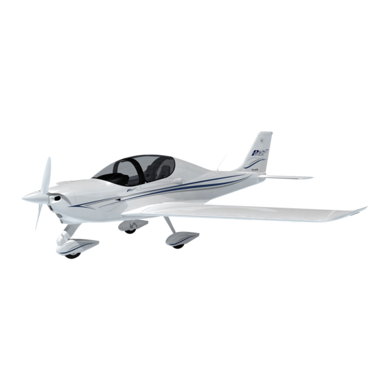
M A I N T E N A N C E M A N U A L 1 – DESCRIPTION & GENERAL CHARACTERISTICS The P2002 Sierra is a twin seat, single engine, low wing, metal structure mono- plane with tricycle landing gear and steerable nose gear. -
Page 8: Primary Dimensions
P2002 Sierra SECTION A pag. GENERAL M A I N T E N A N C E M A N U A L PRIMARY DIMENSIONS WING Wing span 8.6 m Wing surface 11.5 m Wing loading 39 kg/m Aspect ratio... -
Page 9: Engine
P2002 Sierra SECTION A pag. GENERAL M A I N T E N A N C E M A N U A L ENGINE Manufacturer Bombardier-Rotax GmbH Model 912 ULS 4 cylinder horizontally-opposed twins with overall displacement of 1352 c.c., mixed cooling, (water-... -
Page 10: Fuel
P2002 Sierra SECTION A pag. GENERAL M A I N T E N A N C E M A N U A L FUEL • Min. RON 95 Fuel grade • EN 228 Premium • EN 228 Premium plus • AVGAS 100LL (see Flight Manual Sec. -
Page 11: Maximum Weights
P2002 Sierra SECTION A pag. GENERAL M A I N T E N A N C E M A N U A L MAXIMUM WEIGHTS Maximum Takeoff weight 450 kg Maximum Landing weight 450 kg STANDARD WEIGHT Standard empty weight... - Page 12 P2002 Sierra SECTION B M A I N T E N A N C E M A N U A L INSPECTION & SERVICING pag. SECTION B INSPECTION & SERVICING TABLE OF CONTENTS GROUND HANDLING --------------------------------------------------------------------------------------- 2 PARKING AND TIE-DOWN -------------------------------------------------------------------------------- 2...
-
Page 13: Ground Handling
P2002 Sierra SECTION B M A I N T E N A N C E M A N U A L INSPECTION & SERVICING pag. GROUND HANDLING Move the aircraft on ground by pulling on the propeller blades close to hub. - Page 14 P2002 Sierra SECTION B M A I N T E N A N C E M A N U A L INSPECTION & SERVICING pag. B-1 R IGURE EAR LIFTING POINT In case of it would be necessary to lift the nose gear, we suggest you to remove the engine’s cowling and then, acting on the engine’s mount, lift...
-
Page 15: Levelling
P2002 Sierra SECTION B M A I N T E N A N C E M A N U A L INSPECTION & SERVICING pag. LEVELLING Occasional levelling of aircraft may be necessary to insure proper wing in- cidence and/or dihedral or for exact CG location. -
Page 16: Moving Surfaces Control Settings
P2002 Sierra SECTION B M A I N T E N A N C E M A N U A L INSPECTION & SERVICING pag. MOVING SURFACES CONTROL SETTINGS Adjustment of control surfaces must not exceed travel limits reported in table below. -
Page 17: Aircraft Alignments
P2002 Sierra SECTION B M A I N T E N A N C E M A N U A L INSPECTION & SERVICING pag. AIRCRAFT ALIGNMENTS B-4 A IGURE LIGNMENTS Edition, April 22 , 2008... -
Page 18: Datum
P2002 Sierra SECTION B M A I N T E N A N C E M A N U A L INSPECTION & SERVICING pag. DATUM • A & A’ – On the wing upper surface, is the rivet shared between the main spar’s and the composite wing tip rivet lines (of the two... -
Page 19: Weighing And Determination Of Vertical Cg
P2002 Sierra SECTION B M A I N T E N A N C E M A N U A L INSPECTION & SERVICING pag. WEIGHING AND DETERMINATION OF VERTICAL CG USE GUIDELINES AS FOLLOWS: a. Carry out weighing procedure inside hangar b. - Page 20 P2002 Sierra SECTION B M A I N T E N A N C E M A N U A L INSPECTION & SERVICING pag. WEIGHT AND CG DETERMINATION TABLE CMA 1370 B-5 W & B IGURE EIGHT ALANCE 15 mm inboard from rib n°...
-
Page 21: Corrosion Prevention
P2002 Sierra SECTION B M A I N T E N A N C E M A N U A L INSPECTION & SERVICING B-10 pag. CORROSION PREVENTION It is important to keep the aircraft clean and to remove any collection of corrosive agents such as oil, grease, dregs and other foreign matter. -
Page 22: Service Bulletins
P2002 Sierra SECTION B M A I N T E N A N C E M A N U A L INSPECTION & SERVICING B-11 pag. SERVICE BULLETINS ESCRIPTION ALIDITY O Optional P Prescribed R Recommended F Voluntary Edition, April 22... -
Page 23: Servicing
P2002 Sierra SECTION B M A I N T E N A N C E M A N U A L INSPECTION & SERVICING B-12 pag. 10 SERVICING. D a i l y 1 - Pitot and static ports – Check for obstructions. (see sect. E, Pitot &... - Page 24 P2002 Sierra SECTION B M A I N T E N A N C E M A N U A L INSPECTION & SERVICING B-13 pag. 13 - Airspeed system drain – Slide off the left seat, disconnect the hose fit-...
-
Page 25: Lubrication
P2002 Sierra SECTION B M A I N T E N A N C E M A N U A L INSPECTION & SERVICING B-14 pag. 11 LUBRICATION 11.1 INTRODUCTION Periodic lubrication of moving parts insures proper operation and ex- tends parts’... -
Page 26: Lubrication Points (See Fig . B-6 & B-7)
P2002 Sierra SECTION B M A I N T E N A N C E M A N U A L INSPECTION & SERVICING B-15 pag. B-7 L IGURE UBRICATION POINTS Edition, April 22 , 2008... - Page 27 P2002 Sierra SECTION B M A I N T E N A N C E M A N U A L INSPECTION & SERVICING B-16 pag. B-8 L IGURE UBRICATION EVERY HOURS Edition, April 22 , 2008...
-
Page 28: Inspection
P2002 Sierra SECTION B M A I N T E N A N C E M A N U A L INSPECTION & SERVICING B-17 pag. 12 INSPECTION Inspection points that are not in plain view may be accessed through spe-... -
Page 29: Inspection
13 INSPECTION 13.1 INTRODUCTION • TECNAM considers inspection schedule outlined below compulsory for the oper- ational safety of the airframe and of the systems over an extended period of time. Described servicing requirements pertain to operation in non-extreme climatic conditions. -
Page 30: Periodic Inspections
Procedures explained in SERVICING (Chap. 10) are included in the in- spections. Instructions for actions following inspection are detailed in specific sec- tions pertaining to the aircraft group or system. It is suitable to use TECNAM-prepared inspection checklists. 13.3 SERVICING REQUIREMENTS INSPECTION ATURE OF INSPECTION... - Page 31 P2002 Sierra SECTION B M A I N T E N A N C E M A N U A L INSPECTION & SERVICING B-20 pag. INSPECTION ATURE OF INSPECTIONS NTERVALS Special FUEL SYSTEM Check circuit lines for integrity and wetness...
- Page 32 P2002 Sierra SECTION B M A I N T E N A N C E M A N U A L INSPECTION & SERVICING B-21 pag. ISPEZIONE ATURE OF INSPECTIONS NTERVALS Special WING Visually check general condition of wrap-around skin and rivets...
- Page 33 P2002 Sierra SECTION B M A I N T E N A N C E M A N U A L INSPECTION & SERVICING B-22 pag. INSPECTION ATURE OF INSPECTIONS INTERVALS Special NOSE GEAR Inspect support truss for gear strut and attachment hinges...
- Page 34 P2002 Sierra SECTION B M A I N T E N A N C E M A N U A L INSPECTION & SERVICING B-23 pag. REFERENCE MEASUREMENTS SUMMARY TIGHTENING MOMENT FOR ATTACHMENT BOLTS AS A FUNCTION OF SHANK DIAMETER BOLT Class of resistance 8.8...
- Page 35 P2002 Sierra SECTION C M A I N T E N A N C E M A N U A L pag. AIRFRAME SECTION C AIRFRAME TABLE OF CONTENTS 1. WING ......................... 2 2. RIGGING AND DE-RIGGING OF WING ............ 3 2.1.
-
Page 36: Wing
P2002 Sierra SECTION C M A I N T E N A N C E M A N U A L pag. AIRFRAME NTRODUCTION The airframe consists of the following main groups as shown in figure C-1: 1) W INGS... -
Page 37: Rigging And De-Rigging Of Wing
P2002 Sierra SECTION C M A I N T E N A N C E M A N U A L pag. AIRFRAME C-2 R IGURE IGHT TRUCTURE The aileron is constructed of an aluminium spar to which a formed sheet metal skin and metal ribs are attached. - Page 38 P2002 Sierra SECTION C M A I N T E N A N C E M A N U A L pag. AIRFRAME Disconnect the fuel quantity sensor wiring and, if present, the position lights wir- ing. Disconnect flap control (see fig. C-4) by removing roller bearings (6) that link push-pull rods (6) to flap control plate.
-
Page 39: Flap Control ( See Fig . C-4)
P2002 Sierra SECTION C M A I N T E N A N C E M A N U A L pag. AIRFRAME 2.1. . C-4) LAP CONTROL SEE FIG Flap control system is push-pull type. The torque tube (1) is hinged to the cabin truss and connects the two moving surfaces by two levers (2). - Page 40 P2002 Sierra SECTION C M A I N T E N A N C E M A N U A L pag. AIRFRAME The push-pull rod then crosses the wing’s fake spar to transmit motion. Linkage length is adjustable. C-5 A...
-
Page 41: Horizontal Tail
P2002 Sierra SECTION C M A I N T E N A N C E M A N U A L pag. AIRFRAME If control stick should feel unusually hard, reduce cable tension as this may be the primary cause for malfunction; also check that pulleys and other parts of the link system positioned under seats are properly greased. - Page 42 P2002 Sierra SECTION C M A I N T E N A N C E M A N U A L pag. AIRFRAME To remove the stabilator, disconnect the two halves of the tab from each other and from the control rod, remove pins and bolts (7), then remove planes. To avoid cover damage during operation, handle parts by their rigid components.
- Page 43 P2002 Sierra SECTION C M A I N T E N A N C E M A N U A L pag. AIRFRAME If unusual tolerance is found along transmission, replace parts displaying exces- sive wear. The aft bellcrank assembly (see fig. C-8) consists of a steel tube (1) with welded horn assembly (2), attachment for stabilator control shaft (3) and balanced weight bellcrank (4).
-
Page 44: Stabilator Balance
P2002 Sierra SECTION C M A I N T E N A N C E M A N U A L C-10 pag. AIRFRAME To remove stabilator’s torque tube, disconnect electric actuator frame assembly (7) from support (6), release control shaft from aft bellcrank assembly (3) then re- lease horn assembly (2) from brackets (6). - Page 45 P2002 Sierra SECTION C M A I N T E N A N C E M A N U A L C-11 pag. AIRFRAME C-9 F IGURE IN AND RUDDER Rudder mass balancing (10) is placed on the rudder upper rib’s horn. To inspect this part it is necessary to remove the composite tip.
-
Page 46: Fuselage
P2002 Sierra SECTION C M A I N T E N A N C E M A N U A L C-12 pag. AIRFRAME operation must also be checked. To access levers and rudder pedals support, re- move cabin’s central tunnel; for speedier operation remove seats from railings. - Page 47 P2002 Sierra SECTION C M A I N T E N A N C E M A N U A L C-13 pag. AIRFRAME C-11 C IGURE ABIN RUSS C-12 T IGURE Edition, April 22 , 2008...
- Page 48 P2002 Sierra SECTION C M A I N T E N A N C E M A N U A L C-14 pag. AIRFRAME Engine mount is constructed of steel tubing and is secured to the cabin truss via a four-point attachment. Bolts travel through bushings welded on mount, pass through the firewall and exit through other bushings welded to cabin truss.
-
Page 49: Landing Gear
P2002 Sierra SECTION C M A I N T E N A N C E M A N U A L C-15 pag. AIRFRAME LANDING GEAR The main landing gear (see fig. C-13) consists of two special steel spring- leaf struts (1) positioned crossways to fuselage for elastic cushioning of landing loads. - Page 50 P2002 Sierra SECTION C M A I N T E N A N C E M A N U A L C-16 pag. AIRFRAME Control lever (1) activates master cylinder (3) that features built-in brake-fluid reservoir (4). The brake system is equipped with a non-return valve (5), which in- sures that braking action is always effective even if parking brake circuit should accidentally be closed.
-
Page 51: Removal Of The Main Landing Gear Wheel (See Fig. C15)
P2002 Sierra SECTION C M A I N T E N A N C E M A N U A L C-17 pag. AIRFRAME Remove gear strut by pulling it outward from the fuselage. Reinstall using a reverse procedure. It is however necessary to eliminate any trapped air from the brake circuits: once the brake circuit is closed and fluid in reservoir is at normal level, bleed air through dedicated valve. - Page 52 P2002 Sierra SECTION C M A I N T E N A N C E M A N U A L C-18 pag. AIRFRAME C-15 R IGURE EMOVAL OF THE WHEEL Edition, April 22 , 2008...
-
Page 53: Removal Of The Mlg Wheel Roller Berings (See Fig.c16)
P2002 Sierra SECTION C M A I N T E N A N C E M A N U A L C-19 pag. AIRFRAME 6.2. REMOVAL OF THE MLG WHEEL ROLLER BERINGS (SEE FIG.C16) Removal of a wheel bearing becomes necessary when excessive friction occurs during wheel motion. -
Page 54: Nose Landing Gear
P2002 Sierra SECTION C M A I N T E N A N C E M A N U A L C-20 pag. AIRFRAME 6.3. NOSE LANDING GEAR The nose gear (fig. C-17) is attached to the engine mount with two hinges (1) and is equipped with a Sava 4.00-6 type tire. -
Page 55: Nlg Wheel Removal (See Fig.c-18)
P2002 Sierra SECTION C M A I N T E N A N C E M A N U A L C-21 pag. AIRFRAME 6.4. NLG WHEEL REMOVAL (SEE FIG.C-18) To remove the nose gear fairings proceed as follows: To remove front portions of the fairing (5 & 6) loosening the screws (2) and Remove the two fairings (6) and (5). - Page 56 P2002 Sierra SECTION C M A I N T E N A N C E M A N U A L C-22 pag. AIRFRAME C-18 NLG IGURE WHEEL REMOVAL UMMARY OF TIRE INFLATION PRESSURE Nose tire 15 psi (~ 1.0 bar) Main tires 23 psi (~ 1.6 bar)
- Page 57 P2002 Sierra SECTION D pag. POWERPLANT M A I N T E N A N C E M A N U A L SECTION D POWERPLANT TABLE OF CONTENTS 1 - POWERPLANT------------------------------------------------------------------------------------------------------------ 2 1.1 COWLING----------------------------------------------------------------------------------------------------------------------- 2 1.2 ENGINE MAIN FEATURES------------------------------------------------------------------------------------------------- 3 2 - GENERAL SERVICING PROCEDURES---------------------------------------------------------------------------- 4 2.1 I...
-
Page 58: Powerplant
P2002 Sierra SECTION D pag. POWERPLANT M A I N T E N A N C E M A N U A L 1 - POWERPLANT 1.1 COWLING The engine cowling is gull wing type. The cowling is made up of two parts: the upper part consists of a fiberglass nose and a light alloy panel while the bottom part is entirely made of fiberglass. -
Page 59: Engine Main Features
P2002 Sierra SECTION D pag. POWERPLANT M A I N T E N A N C E M A N U A L 1.2 ENGINE MAIN FEATURES The installed engine is a BOMBARDIER-ROTAX type 912 ULS horizon- tally-opposed four-cylinder, one central camshaft with pushrods and OHV. -
Page 60: General Servicing Procedures
P2002 Sierra SECTION D pag. POWERPLANT M A I N T E N A N C E M A N U A L 2 - GENERAL SERVICING PROCEDURES 2.1 IDLE SPEED SYNCHRONIZATION With the exception of idle speed synchronization, no other carb. regulations are required. -
Page 61: Periodic Inspection
P2002 Sierra SECTION D pag. POWERPLANT M A I N T E N A N C E M A N U A L After correct installation of propeller and before takeoff, let the engine run for a few minutes and, after turning it off, carry out further inspection (tightness, overall state, etc.). - Page 62 P2002 Sierra SECTION E M A I N T E N A N C E M A N U A L SYSTEMS SECTION E SYSTEMS TABLE OF CONTENTS 1 – FUEL SYSTEM----------------------------------------------------------------------------------------------------- 2 2 - INSTRUMENTS ---------------------------------------------------------------------------------------------------- 5 2.1 - E...
-
Page 63: Fuel System
P2002 Sierra SECTION E M A I N T E N A N C E M A N U A L SYSTEMS 1 – FUEL SYSTEM The system is equipped with two aluminium fuel tanks (1) integrated within the wing leading edge and accessible for inspection through dedicated doors (2). Ca- pacity of individual tank is 50lt for a total of 100lt. - Page 64 P2002 Sierra SECTION E M A I N T E N A N C E M A N U A L SYSTEMS the instrument panel and fed directly from the fuel manifold “X” connection (11) by a firewall pass through hose.
- Page 65 P2002 Sierra SECTION E M A I N T E N A N C E M A N U A L SYSTEMS The figure E-3 shows a schematic of the fuel system. E-3 F IGURE YSTEM AYOUT Edition, April 22...
-
Page 66: Instruments
P2002 Sierra SECTION E M A I N T E N A N C E M A N U A L SYSTEMS 2 - INSTRUMENTS The aluminium instrument panel (see Fig. E-4) is sub-divided in three distinct ar- eas: The left area holds flight instruments, the right area holds engine controls and the central area can holds nav/com instruments (if installed). -
Page 67: Engine Instrumentation
P2002 Sierra SECTION E M A I N T E N A N C E M A N U A L SYSTEMS 2.1 - ENGINE INSTRUMENTATION An electric tachometer is installed; An electric oil temperature indicator is installed. The sensor is located on the oil pump tube and is marked with “TO”... -
Page 68: Pitot And Static System
P2002 Sierra SECTION E M A I N T E N A N C E M A N U A L SYSTEMS 3 - PITOT AND STATIC SYSTEM Referring to figure E-6, system consists of an airspeed sensor assembly (1) mounted below the left wing. -
Page 69: Exhaust Manifolds
P2002 Sierra SECTION E M A I N T E N A N C E M A N U A L SYSTEMS 4 - EXHAUST MANIFOLDS With reference to figure E-7, exhaust manifolds (1) are flanged to the engine and join the muffler separately (2). - Page 70 P2002 Sierra SECTION E M A I N T E N A N C E M A N U A L SYSTEMS to avoid any kind of exhausted gas intrusion from the muffler into the heating system. Inspection should also recommended to the cabin hot air shut-off valve.
-
Page 71: Brake System
P2002 Sierra SECTION E E-10 M A I N T E N A N C E M A N U A L SYSTEMS 6 - BRAKE SYSTEM The brake system consists of a brake fluid reservoir (1), a master cylinder (2) and two disc brakes assemblies (3);... -
Page 72: Brakes Lining Replacement
P2002 Sierra SECTION E E-11 M A I N T E N A N C E M A N U A L SYSTEMS D) Pull brake lever (5) to pressurize circuit; E) Loosen small escape valve (7) allowing fluid spurt;... - Page 73 P2002 Sierra SECTION F ELECTRICAL pag. M A I N T E N A N C E M A N U A L SYSTEM SECTION F ELECTRICAL SYSTEM TABLE OF CONTENTS 1 - GENERAL................................. 2 2 - BATTERY................................. 4 2.1 - BATTERY REMOVAL........................... 4 2.2 - BATTERY CHECK............................
-
Page 74: General
P2002 Sierra SECTION F ELECTRICAL pag. M A I N T E N A N C E M A N U A L SYSTEM 1 - GENERAL The aircraft's electrical system consists of a 12 Volt DC circuit. An 18 Ah lead... - Page 75 P2002 Sierra SECTION F ELECTRICAL pag. M A I N T E N A N C E M A N U A L SYSTEM The positive end of the rectifier is connected to the primary bus through a 50 Amp circuit breaker mounted on firewall.
-
Page 76: Battery
P2002 Sierra SECTION F ELECTRICAL pag. M A I N T E N A N C E M A N U A L SYSTEM 2 - BATTERY The battery is lead-type (model FIAMM 6H4P) and provides 12V DC current with a capacity of 0.9 A for 20 hours. -
Page 77: Generator
P2002 Sierra SECTION F ELECTRICAL pag. M A I N T E N A N C E M A N U A L SYSTEM D) First connect positive cable and then the negative to battery terminals and apply protective grease to terminals;... -
Page 78: Exterior Lighting
P2002 Sierra SECTION F ELECTRICAL pag. M A I N T E N A N C E M A N U A L SYSTEM 5 - EXTERIOR LIGHTING Exterior lighting consists of: Navigation lights (optional) Landing light (optional) Strobe Light (optional) 6.1 - POSITION LIGHTS (O... -
Page 79: Flap System
P2002 Sierra SECTION F ELECTRICAL pag. M A I N T E N A N C E M A N U A L SYSTEM 7 - FLAP SYSTEM The flap system is made up of an electric actuator, a shunt and by a position indicator instrument.
Need help?
Do you have a question about the P2002 Sierra and is the answer not in the manual?
Questions and answers