Tecnam P2006T Flight Manual
Hide thumbs
Also See for P2006T:
- Aircraft flight manual (509 pages) ,
- Flight manual (150 pages) ,
- Manual (1383 pages)
Table of Contents
Advertisement
M
:
ANUFACTURER
COSTRUZIONI AERONAUTICHE
A
: P2006T
IRCRAFT MODEL
EASA T
C
YPE
ERTIFICATE
S
: ................................
ERIAL NUMBER
B
: ......................................
UILD YEAR
R
EGISTRATION MARKINGS
This Aircraft Flight Manual is approved by European Aviation Safety Agency
(EASA).
This Manual contains information required by the FAA to be furnished to the pilot
for operation in the U.S.A. plus information supplied by the manufacturer. It is
approved by EASA on behalf of the FAA per FAR 21.29.
This Manual must be carried in the airplane at all times.
The airplane has to be operated in compliance with procedures and limitations
contained herein.
Costruzioni Aeronautiche TECNAM srl
Via Maiorise
CAPUA (CE) – Italy
Tel. +39 (0) 823.62.01.34
WEB:
www.tecnam.com
Aircraft Flight Manual
Doc. No. 2006/044
4
Edition – Rev. 5
th
2018, January 12
TECNAM P2006T
TECNAM
N
: A .185 (
O
DATED
: ..................
th
S.r.l.
2009, J
5
)
TH
UNE
Page 0 - 1
Advertisement
Table of Contents

Related Manuals for Tecnam P2006T


Summary of Contents for Tecnam P2006T
- Page 1 EASA on behalf of the FAA per FAR 21.29. This Manual must be carried in the airplane at all times. The airplane has to be operated in compliance with procedures and limitations contained herein. Costruzioni Aeronautiche TECNAM srl Via Maiorise CAPUA (CE) – Italy Tel. +39 (0) 823.62.01.34 WEB: www.tecnam.com...
- Page 2 Page 0 - 2 SECTION 0 INDEX RECORD OF REVISIONS ............... 3 LIST OF EFFECTIVE PAGES ............7 FOREWORD ................. 10 SECTIONS LIST ................11 Edition - Rev. 0 Aircraft Flight Manual INDEX...
- Page 3 Page 0 - 3 1. RECORD OF REVISIONS Any revision to the present Manual, except actual weighing data, is recorded: a Record of Revisions is provided at the front of this manual and the operator is ad- vised to make sure that the record is kept up-to-date. The Manual issue is identified by Edition and Revision codes reported on each page, lower right side.
- Page 4 Page 0 - 4 EASA Approval or Tecnam Approval Revised Description of Under DOA page Revision Privileges First issue D. Ronca M. Oliva M. Oliva 0-4,8 Amended ROR and LOEP Approved under the au- thority of DOA, 6-12 Amended Equipment List D.
- Page 5 Page 0 - 5 INTENTIONALLY LEFT BLANK Edition - Rev. 0 Aircraft Flight Manual...
- Page 6 Page 0 - 6 INTENTIONALLY LEFT BLANK Edition - Rev. 0 Aircraft Flight Manual...
- Page 7 Page 0 - 7 2. LIST OF EFFECTIVE PAGES The List of Effective Pages (LOEP), applicable to manuals of every operator, lists all the basic AFM pages: each manual could contain either basic pages or one variant of these pages when the pages of some Supplements are embodied. Should the Supplements be embodied in accordance with approved instructions, make reference to the LOEP addressed on the Supplements themselves.
- Page 8 Page 0 - 8 INTENTIONALLY LEFT BLANK Edition - Rev. 0 Aircraft Flight Manual...
- Page 9 Page 0 - 9 INTENTIONALLY LEFT BLANK Edition - Rev. 0 Aircraft Flight Manual...
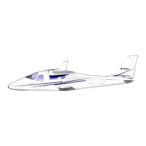
- Page 10 Page 0 - 10 3. FOREWORD Tecnam P2006T is a twin-engine four-seat aircraft with high cantilevered wing and tri- cycle retractable landing gear. Section 1 supplies general information and it contains definitions, symbols explana- tions, acronyms and terminology used. Before using the airplane, you are recommended to read carefully this manual: a deep knowledge of airplane features and limitations will allow you for operating the airplane safely.
- Page 11 Page 0 - 11 4. SECTIONS LIST General Section 1 (a non-approved Chapter) Section 2 - EASA Approved Chapter Limitations Emergency Procedures Section 3 (a non-approved Chapter) Normal Procedures Section 4 (a non-approved Chapter) Performances Section 5 (a non-approved Chapter) Weight and Balance Section 6 (a non-approved Chapter) Airframe and Systems description Section 7 (a non-approved Chapter)
- Page 12 Page 0 - 12 INTENTIONALLY LEFT BLANK Edition - Rev. 4 Aircraft Flight Manual...
- Page 13 Page 1 - 1 SECTION 1 - GENERAL INDEX 1. Introduction .................. 3 2. Three-view and dimensions ............4 3. Control Surfaces Travel Limits ............ 6 4. Engine ................... 6 5. Propeller ..................6 6. Governor ..................7 7. Fuel ....................7 8.
- Page 14 Page 1 - 2 INTENTIONALLY LEFT BLANK Edition, Rev 0 Section 1 – General...
- Page 15 NTRODUCTION The Aircraft Flight Manual has been implemented to provide the owners with in- formation for a safe and efficient use of the aircraft TECNAM P2006T. Warning – Caution – Note Following definitions apply to warnings, cautions and notes used in the Aircraft Flight Manual.
- Page 16 Page 1 - 4 2. T HREE VIEW AND DIMENSIONS Figure 1 – General views Edition, Rev 0 Section 1 – General THREE-VIEW AND DIMENSIONS...
- Page 17 Page 1 - 5 Dimensions Overall dimensions Wingspan 11,4 m 37,4 ft Length 8,7 m 28,5 ft Overall height 2,58 m 8,46 ft Wing Wing surface 14,76 m 158,9 ft Mean Geometric Chord 1,295 m 4,25 ft Dihedral 1° Aspect ratio 8,80 Main Landing Gear Track...
- Page 18 Page 1 - 6 3. C ONTROL URFACES RAVEL IMITS Ailerons Up 20° Down 17 ° ( 2°) Stabilator (refer to Trailing Edge) Up 4° Down 15° ( 2°) Stabilator trim tab (refer to Trailing Edge) Up 2°; Down 19° ( 2°) Rudder RH 26°...
- Page 19 Page 1 - 7 OVERNOR Manufacturer Mt Propeller Model P-875-12 Type Hydraulic 7. F Approved fuel: MOGAS ASTM D4814 MOGAS EN 228 Super/Super plus (min. RON 95) AVGAS 100LL (ASTM D910) (see also Section 2) Fuel tanks Two integrated tanks (one in each wing) fitted with drainable sump and drain valve Capacity of each wing tan...
- Page 20 Page 1 - 8 9. C OOLING Cooling system Ram-air cooled cylinders, liquid cooled cylinder heads (closed and pressurized circuit) Coolant liquid Certified for Water/Coolant mixture. Make reference to “Rotax Operators Manual” – last issue Overall circuit capacity 1410 cm WEIGHTS See Section 2.
- Page 21 Page 1 - 9 INTENTIONALLY LEFT BLANK Edition, Rev 0 Section 1 – General GENERAL FEATURES...
- Page 22 Page 1 - 10 13. A CRONYMS AND TERMINOLOGY KCAS Calibrated Airspeed is the indicated airspeed expressed in knots, corrected taking into account the errors related to the instrument itself and its installation. KIAS Indicated Airspeed is the speed shown on the airspeed indicator and it is expressed in knots.
- Page 23 Page 1 - 11 Meteorological terminology International Standard Atmosphere: is the air atmospheric standard condition at sea level, at 15°C (59°F) and at 1013.25hPa (29.92inHg). Official atmospheric pressure at airport level: it indicates the air- craft absolute altitude with respect to the official airport level. Theoretical atmospheric pressure at sea level: is the atmospheric pressure reported at the medium sea level, through the standard air pressure-altitude relationship, starting from the airport QFE.
- Page 24 Page 1 - 12 Aircraft performance and flight planning terminology is the velocity of the crosswind component Crosswind Velocity for the which adequate control of the air- plane during takeoff and landing is assured. Usable fuel is the fuel available for flight planning. is the quantity of fuel that cannot be safely Unusable fuel used in flight.
- Page 25 Maximum Landing Weight is the maximum weight approved for the landing touchdown (for P2006T it is equiv- alent to the Maximum Takeoff Weight). Edition, Rev 0 Section 1 – General ACRONYMS AND TERMINOLOGYACRONYMS AND...
- Page 26 Page 1 - 14 INTENTIONALLY LEFT BLANK Edition, Rev 0 Section 1 – General...
- Page 27 Page 1 - 15 14. U NIT CONVERSION CHART MOLTIPLYING YIELDS EMPERATURE Fahrenheit [°F] Celsius [°C] [°F] Celsius [°C] Fahrenheit ORCES Kilograms [kg] 2.205 Pounds [lbs] Pounds [lbs] 0.4536 Kilograms...
- Page 28 Page 1 - 16 15. L / US ITRES GALLONS CONVERSION CHART Litres US Gallons US Gallons Litres 11.4 15.1 22.7 30.3 37.9 10.6 45.4 11.9 53.0 13.2 60.6 15.9 68.1 18.5 75.7 21.1 83.3 23.8 90.9 26.4 98.4 29.1 106.0 31.7 113.6...
- Page 29 Page 1 - 17 INTENTIONALLY LEFT BLANK Edition, Rev 0 Section 1 – General...
- Page 30 Page 1 - 18 INTENTIONALLY LEFT BLANK Edition, Rev 0 Section 1 – General...
- Page 31 Page 2 - 1 SECTION 2 – LIMITATIONS INDEX Introduction ......................3 Speed limitations ....................5 Airspeed indicator markings ................7 Powerplant limitations ..................9 Lubricant ......................10 Coolant liquid ....................10 Propeller ......................10 Governor ......................10 Maximum operating altitude ................11 Ambient temperature ..................
- Page 32 Page 2 - 2 INTENTIONALLY LEFT BLANK Edition, Rev. 0 Section 2 – Limitations...
- Page 33 Page 2 - 3 1. I NTRODUCTION Section 2 includes operating limitations, instrument markings and basic placards necessary for safe operation of P2006T aircraft, its engines and standard systems and equipment. This AFM Section is EASA approved. EASA Approved Edition, Rev. 0 Section 2 –...
- Page 34 Page 2 - 4 INTENTIONALLY LEFT BLANK Edition, Rev. 0 Section 2 – Limitations...
- Page 35 Page 2 - 5 2. S PEED LIMITATIONS The following table addresses the airspeed limitations and their operational signifi- cance: SPEED KIAS KCAS REMARKS V NE Never exceed speed Do not exceed this speed in any operation. Maximum Structural Cruising Do not exceed this speed V NO Speed...
- Page 36 Page 2 - 6 INTENTIONALLY LEFT BLANK Edition, Rev. 0 Section 2 – Limitations...
- Page 37 Page 2 - 7 3. A IRSPEED INDICATOR MARKINGS Airspeed indicator markings and their colour code are explained in the following table. MARKING KIAS EXPLANATION White arc 53-93 Lower limit is V , upper limit is the maxi- mum allowable speed with flaps extended in FULL position.
- Page 38 Page 2 - 8 INTENTIONALLY LEFT BLANK Edition, Rev. 0 Section 2 – Limitations...
- Page 39 Page 2 - 9 4. P OWERPLANT LIMITATIONS Following table reports the operating limitations for both engines installed: : Bombardier Rotax GmbH. NGINE MANUFACTURER : 912 S3 NGINE MODEL AXIMUM POWER Max Power Max rpm. Time max. kW (hp) Prop. rpm (engine) (minutes) Max.
- Page 40 Page 2 - 10 Fuel pressure: Minimum 2.2 psi (0.15 Bar) Maximum 5.8 psi (0.40 Bar) or 7.26 psi* (0.5 Bar) *only applicable for fuel pump part no. 893110 or 893114 5. L UBRICANT Use only oil with API classification “SG” or higher. For additional info, refer to “Rotax Operators Manual”...
- Page 41 Page 2 - 11 9. M AXIMUM OPERATING ALTITUDE Maximum operating altitude is 14000 ft (4260 m) MSL. Flight crew is required to use supplemental oxygen according to applicable Air Operation Rules. CAUTION 10. A MBIENT TEMPERATURE Ambient temperature: from -25°C to +50°C. Flight in expected and/or known icing conditions is forbidden.
- Page 42 Page 2 - 12 11. P OWERPLANT INSTRUMENTS MARKINGS Powerplant instrument markings and their colour code significance are shown below: RED LINE GREEN ARC YELLOW ARC RED LINE Minimum Normal Caution Maximum NSTRUMENT limit operating limit Propeller ---- 580 - 2265 2265 - 2388 2388 90 –...
- Page 43 Page 2 - 13 13. W ARNINGS CAUTIONS AND ADVISORIES LIGHTS Following table addresses the warning, caution and advisory lights installed (unless differently specified) on the annunciator panel: Warnings (RED) Cause LH OVERVOLT LH electric system overvoltage RH OVERVOLT RH electric system overvoltage MAIN DOOR OPEN ALERT Main door open and/or unlocked REAR DOOR OPEN ALERT...
- Page 44 Page 2 - 14 INTENTIONALLY LEFT BLANK Edition, Rev. 0 Section 2 – Limitations...
- Page 45 Page 2 - 15 14. W EIGHTS Condition Weight Maximum takeoff weight 1180 kg 2601 lb Maximum landing weight 1180 kg 2601 lb Maximum zero wing fuel weight 1145 kg 2524 lb Refer to Para. 21.4 of this AFM Section for baggage loading limitations. NOTE EASA Approved Edition, Rev.
- Page 46 Page 2 - 16 INTENTIONALLY LEFT BLANK Edition, Rev. 0 Section 2 – Limitations...
- Page 47 Page 2 - 17 15. C ENTER OF GRAVITY RANGE Datum Vertical plane tangent to the wing leading edge (the aircraft must be levelled in the longitudinal plane) Levelling Refer to the seat track supporting beams (see procedure in Section 6) Forward limit 0.221 m (16.5% MAC) aft of datum for all weights Aft limit...
- Page 48 Page 2 - 18 INTENTIONALLY LEFT BLANK Edition, Rev. 0 Section 2 – Limitations...
- Page 49 Page 2 - 19 16. A PPROVED MANEUVERS The aircraft is certified in normal category in accordance with EASA CS-23 regula- tion. Non aerobatic operations include: Any manoeuvre pertaining to “normal” flight Stalls (except whip stalls) Lazy eights ...
- Page 50 Page 2 - 20 19. F LIGHT CONDITIONS The aircraft can be equipped for following flight operations (make reference to Pa- ra. 22 concerning the equipment list required on board to allow them): VFR Day and Night IFR Day and Night including IMC Flight in expected and/or known icing conditions, in proximity of storms or in turbulence is forbidden.
- Page 51 Page 2 - 21 21. L IMITATIONS PLACARDS Hereinafter the placards, related to the operating limitations and installed on P2006T, are reported. 21.1. PEED LIMITATIONS On the left side instrument panel, above on the left, it is placed the following plac-...
- Page 52 Page 2 - 22 21.2. PERATING LIMITATIONS On the instrument panel, it is placed the following placard reminding the ob- servance of aircraft operating limitations; make reference to Para. 22 for the list of equipment required on board to allow flight operations in VFR Day, VFR Night, IFR Day and IFR Night conditions.
- Page 53 Page 2 - 23 21.3. NFLIGHT ENGINE RESTART The inflight engine restart procedure is reported on a placard (shown below) in- stalled on the central console. 21.4. AGGAGE COMPARTMENT CAPACITY The placard shown below, and installed on the baggage compartment (vertical pan- el), concerns the baggage compartment load limitations herein reported: ...
- Page 54 Page 2 - 24 21.5. NGINE OIL LEVEL On the engine nacelle, in correspondence of the engine oil reservoir access door, it is located the following placard addressing the limitations concerning the oil level, the oil volume and the oil type. 21.6.
- Page 55 Page 2 - 25 21.7. ANDING YDRAULIC YSTEM The placard shown below, and located on the tail cone, concerns the allowed low pressure limit for the landing gear emergency accumulator. The low pressure limit is 20 bar. If during pre-flight inspection the value is below 20 bar, the system must be re- charged by means of the override button (see Section 7, Para.
- Page 56 Page 2 - 26 21.8. EAR SEATS During Taxi, Take OFF, Landing (including Emergency Landing), both rear seats must be kept in the lowest and full aft position. The following placard is located aside both rear seats. EASA Approved Edition, Rev. 0 Section 2 –...
- Page 57 Page 2 - 27 21.9. THER PLACARDS Description Placard Place Smoking ban Instruments panel, right side Ditching emer- Ditching emergency gency exit: exit handle: internal opening side structions Ditching emer- Ditching emergency gency exit: exit handle: external opening side structions Door locking Main door and emer-...
- Page 58 Page 2 - 28 INTENTIONALLY LEFT BLANK Edition, Rev. 0 Section 2 – Limitations Edition, Rev.0...
- Page 59 Page 2 - 29 INDS OF PERATIONS QUIPMENT This paragraph reports the KOEL table, concerning the equipment list required on board under CS-23 regulations to allow flight operations in VFR Day, VFR Night, IFR Day and IFR Night conditions. Flight in VFR Day and Night, IFR Day and Night is permitted only if the pre- scribed equipment is installed and operational.
- Page 60 Page 2 - 30 Equipment VFR Day VFR Night IFR Day IFR Night Magnetic compass ● ● ● ● Airspeed indicator ● ● ● ● Altimeter ● ● ● ● Vertical speed indicator ● ● ● ● Attitude indicator (electric) ●...
- Page 61 Page 2 - 31 INTENTIONALLY LEFT BLANK Edition, Rev. 0 Section 2 – Limitations...
- Page 62 Page 2 - 32 INTENTIONALLY LEFT BLANK Edition, Rev. 0 Section 2 – Limitations...
- Page 63 Page 3 - 1 SECTION 3 – EMERGENCY PROCEDURES INDEX 1. Introduction ..................3 1.1. Engine failure during takeoff run ..............3 2. Airplane alerts ................. 5 2.1. Single generator failure / overvoltage ............5 2.2. Both generators failure ................... 6 2.3.
- Page 64 Page 3 - 2 7.3. Partial Main LG extension ................34 7.4. Failed retraction .................... 36 7.5. Unintentional landing gear extension ............36 8. Smoke and fire occurrence ............38 8.1 Engine fire on the ground ................38 8.2 Engine fire during takeoff run ............... 39 8.3 Engine fire in flight ..................
- Page 65 Page 3 - 3 1. I NTRODUCTION Section 3 includes checklists and detailed procedures for coping with various types of emergency conditions that could arise after a system failure. Before operating the aircraft, the pilot should become thoroughly familiar with this manual and, in particular, with this Section.
- Page 66 Page 3 - 4 In this Chapter, following definitions apply: NOTE Land as soon as possible: land without delay at the nearest suitable area at which a safe approach and landing is assured. Land as soon as practical: land at the nearest approved landing ar- ea where suitable repairs can be made.
- Page 67 Page 3 - 5 2. A IRPLANE ALERTS The annunciator panel, located on the left side instrument panel, contains 16 lights for warnings, cautions and advisories. The colours are as follows: GREEN: to indicate that pertinent device is turned ON AMBER: to indicate no-hazard situations which have to be considered and which require a proper crew action...
- Page 68 Page 3 - 6 2.2. OTH GENERATORS FAILURE In event of both LH and RH GENERATOR caution lights turned ON: 1. FIELD LH and RH BOTH OFF 2. FIELD LH and RH BOTH ON If the LH (or RH) GENERATOR caution stays displayed 3.
- Page 69 Page 3 - 7 2.3. B OTH GENERATORS OVERVOLTAGE In event of both LH and RH OVERVOLT warning lights turned ON: 1. FIELD LH and RH BOTH OFF 2. FIELD LH and RH BOTH ON If the LH (or RH) GENERATOR caution stays displayed 3.
- Page 70 Page 3 - 8 2.4. F AILED DOOR CLOSURE In case of door opening / unlocking, related MAIN or REAR DOOR ALERT warning light turns ON. ON THE GROUND 1. Passengers and crew seat belts Fasten and tighten 2. Affected door Verify correctly closed If door is open 3.
- Page 71 Page 3 - 9 2.5. P ITOT HEATING SYSTEM FAILURE When the Pitot Heating system is activated, the green PITOT HEAT advisory light is turned ON. If the amber PITOT HEAT caution light turns OFF, then the Pitot Heating sys- tem is functioning properly.
- Page 72 Page 3 - 10 2.6. C OOLANT LIQUID LOW LEVEL When the engine coolant liquid level goes under the lower limit, the related LH or RH LOW COOLANT is turned ON. This condition may lead to high CHT/CT. When the warning light turns ON, apply following procedure: 1.
- Page 73 Page 3 - 11 2.7. G UMP FAILURE The GEAR PUMP ON caution light turns ON when the landing gear hydraulic pump is electrically supplied. After the landing gear retraction, if the red TRANS light turns OFF and the GEAR PUMP ON caution stays turned ON, this could indicate a gear pump relay failure to ON.
- Page 74 Page 3 - 12 2.8. E NGINE FIRE In event of engine fire, LH or RH ENGINE FIRE warning light will turn ON. Re- fer to following procedures: FIRE ON THE GROUND: see Para. 8.1 FIRE DURING TAKEOFF RUN: see Para. 8.2 FIRE IN FLIGHT: see Para.
- Page 75 Page 3 - 13 3. E NGINE SECURING Following procedure is applicable to shut-down one engine in flight: Throttle Lever IDLE Ignition BOTH OFF Propeller Lever FEATHER Fuel Selector Electrical fuel pump After securing engine(s), after analysing situation, refer immediately to following procedures: ENGINE FAILURE IN FLIGHT: see Para.
- Page 76 Page 3 - 14 4. P OWERPLANT EMERGENCIES 4.1. ROPELLER OVERSPEEDING The aircraft is fitted with propeller/governor set by MT-Propeller such a way that the maximum propeller rpm exceedance is prevented. In case of propeller over- speeding in flight, apply following procedure: Throttle Lever REDUCE power to minimum practical Propeller Lever...
- Page 77 Page 3 - 15 4.3. IL TEMPERATURE LIMIT EXCEEDANCE If oil temperature exceeds maximum limit (130°C): 1. OIL PRESS CHECK If oil pressure is within limits 2. Affected engine Reduce power setting to minimum applicable 3. Affected engine Keep propeller speed higher than 2000 RPM If oil pressure does not decrease 4.
- Page 78 Page 3 - 16 4.4. IL PRESSURE LIMITS EXCEEDANCE If oil pressure exceeds its lower or upper limit (0.8 – 7 bar), apply following pro- cedure: Excessive oil pressure drop leads to a high pitch propeller configuration with consequent propeller feathering and en- gine stopping.
- Page 79 Page 3 - 17 4.5. OW FUEL PRESSURE If fuel pressure decreases below the lower limit (2.2 psi), apply following proce- dure: Fuel press CHECK Fuel quantity CHECK Fuel consumption MONITOR If a fuel leakage is deemed likely Land as soon as possible. If a fuel leakage can be excluded: Electrical fuel pump Feed the affected engine by means of opposite side fuel tank...
- Page 80 Page 3 - 18 5. O THER EMERGENCIES 5.1. MERGENCY DESCENT Descent with airspeed at VLE, idle power and gear down will pro- ° vide high descent rates and pitch attitudes up to -15 Anticipate altitude capture and return to level flight during emer- gency descent in order to assure a safe and smooth recovery from CAUTION maneuver.
- Page 81 Page 3 - 19 5.3. TATIC PORTS FAILURE In case of static ports failure, the alternate static port in the cabin (shown below) must be activated. Cabin ventilation OFF (hot and cold air) ALTERNATE STATIC PORT VALVE OPEN Continue the mission Edition, Rev.
- Page 82 Page 3 - 20 5.4. NINTENTIONAL FLIGHT INTO ICING CONDITIONS Carburettor heat BOTH ON Pitot heat Fly as soon as practical toward a zone clear of visible moisture, precipita- tion and with higher temperature, changing altitude and/or direction. Control surfaces Move continuously to avoid locking Propellers rpm INCREASE to prevent ice build-up on the blades...
- Page 83 Page 3 - 21 5.5. ARBURETTOR ICING DURING TAKEOFF The carburettor icing in “full throttle” mode is unlikely. Take off in known or suspected icing condition is forbidden. Therefore, and in order to dispose of full engine take off power, the take-off must be performed with carburettor heating OFF.
- Page 84 Page 3 - 22 5.6. LAPS CONTROL FAILURE DURING TAKEOFF Flap UP take off, requires a T/O distance (50 ft height obstacle distance) increased by about 20%. CAUTION Airspeed Keep below 93 KIAS Land as soon as practical DURING APPROACH/LANDING If the flaps control fails, consider the higher stall speed (see Sec- tion 5, Para 6 (Stall Speed) and an increased landing distance of about 25%.
- Page 85 Page 3 - 23 6. O NE ENGINE INOPERATIVE PROCEDURES The ineffectiveness of one engine results in asymmetric traction which tends to yaw and bank the aircraft towards the inoperative engine. In this condition it is essential to maintain the direction of flight compen- sating the lower traction and counteracting the yawing effects by mean of rudder pedals.
- Page 86 Page 3 - 24 HARACTERISTIC AIRSPEEDS WITH ONE ENGINE INOPERATIVE In case of one engine inoperative condition (OEI), pilot shall take into account the airspeeds shown below: Speed Conditions (KIAS) Minimum aircraft control speed with one en- gine inoperative and flaps set to T.O. (V MTOW 1180 kg MTOW 1230 kg Best rate-of-climb speed OEI (V...
- Page 87 Page 3 - 25 NFLIGHT ENGINE RESTART After: mechanical engine seizure; fire; major propeller damage WARNING engine restart is not recommended. Carburettor heat ON if required Electrical fuel pump Fuel quantity indicator CHECK Fuel Selector CHECK (Crossfeed if required) FIELD Ignition BOTH ON Operating engine Throttle Lever...
- Page 88 Page 3 - 26 NGINE FAILURE DURING TAKEOFF RUN BEFORE ROTATION: ABORT TAKE OFF Throttle Lever BOTH IDLE Rudder Keep heading control Brakes As required When safely stopped: Failed Engine Ignition BOTH OFF Failed Engine Field Failed Engine Electrical fuel pump IF THE DECISION IS TAKEN TO CONTINUE THE TAKEOFF: A take-off abort should always be preferred if a safe stop can be per- formed on ground.
- Page 89 Page 3 - 27 At safe altitude Inoperative engine Confirm and SECURE Operative engine Electrical fuel pump Check ON Operating engine Check engine instruments Operating engine Fuel Selector Check correct feeding (crossfeed if needed) If engine restart is recommended: Apply INFLIGHT ENGINE RESTART procedure see Para 6.2 If engine restart is unsuccessful or it is not recommended: Land as soon as possible...
- Page 90 Page 3 - 28 NGINE FAILURE DURING CLIMB Autopilot Heading Keep control using rudder and ailerons Attitude Reduce as appropriate to keep airspeed over 62 KIAS Operating engine Throttle Lever FULL THROTTLE Operating engine Propeller Lever FULL FORWARD Operative engine Electrical fuel pump Check ON Inoperative engine Propeller Lever FEATHER...
- Page 91 Page 3 - 29 6.5. E NGINE FAILURE IN FLIGHT Autopilot Heading Keep control using rudder and ailerons Attitude Adjust as appropriate to keep airspeed over 62 KIAS Operating engine Monitor engine instruments Operative engine Electrical fuel pump Check ON Operating engine Fuel Selector Check correct feeding (crossfeed if needed)
- Page 92 Page 3 - 30 6.6. One engine inoperative landing Thoroughly evaluate feasibility and plan in advance Single Engine Go- Around capabilities and expected climb gradient should a Missed Ap- proach / balked landing be necessary. Refer to Section 5, Para 13 and 14 (One-engine Rate of Climb at V and V WARNING...
- Page 93 Page 3 - 31 INTENTIONALLY LEFT BLANK Edition, Rev. 0 Section 3 – Emergency procedures...
- Page 94 Page 3 - 32 7. L ANDING GEAR FAILURES 7.1. MERGENCY LANDING GEAR EXTENSION Landing gear extension failure is identified by means of the green NOTE lights not illuminated: relevant gear leg may not be fully extended and/or locked. Light bulb operating status can be verified by pressing the LDG push-to-test button.
- Page 95 Page 3 - 33 7.2. NOSE GEAR UP LANDING OMPLETE EAR UP OR The following procedure applies if Nose Landing Gear is not extended and locked even after emergency extension procedure. CAUTION A Nose Landing Gear up leg not down and locked might lead to a hazardous situation, especially on uneven runways.
- Page 96 Page 3 - 34 Consider use of ditching emergency exit to escape in case pilot or passenger doors are blocked, watch for engine hot parts, fuel, hydraulic fluid or oil spills. Leave aircraft in upwind di- WARNING rection. 7.3. ARTIAL EXTENSION The following procedure applies if one or both Main Landing Gear legs are not completely extended and locked even after emergency ex-...
- Page 97 Page 3 - 35 After aircraft stops: FIELD LH and RH BOTH OFF MASTER SWITCH Master switch to OFF impairs radio communication and outside air- craft lighting. CAUTION Aircraft Evacuation carry out Consider use of ditching emergency exit to escape in case pilot or passenger doors are blocked, watch for engine hot parts, fuel, hydraulic fluid or oil spills.
- Page 98 Page 3 - 36 7.4. AILED RETRACTION Airspeed Keep below applicable VLO/VLE Landing gear control lever DOWN A Landing Gear lever recycle (further retraction attempt) may result in a final partial Landing Gear Extension, which may then compromise safe landing aircraft capability. WARNING Landing Gear lights Check...
- Page 99 Page 3 - 37 INTENTIONALLY LEFT BLANK Edition, Rev. 0 Section 3 – Emergency procedures...
- Page 100 Page 3 - 38 8. S MOKE AND FIRE OCCURRENCE NGINE FIRE ON THE GROUND Fuel Selectors BOTH OFF Ignitions ALL OFF Electrical fuel pumps BOTH OFF Cabin heat and defrost MASTER SWITCH Parking Brake ENGAGED Aircraft Evacuation carry out immediately Consider use of ditching emergency exit to escape in case pilot or passenger doors are blocked, watch for engine hot parts, fuel, hydraulic fluid or oil spills.
- Page 101 Page 3 - 39 NGINE FIRE DURING TAKEOFF RUN BEFORE ROTATION: ABORT TAKE OFF Throttle Lever BOTH IDLE Rudder Keep heading control Brakes As required With aircraft under control Fuel Selector BOTH OFF Ignitions ALL OFF Electrical fuel pump BOTH OFF Cabin heat and defrost MASTER SWITCH Parking Brake...
- Page 102 Page 3 - 40 At safe altitude Cabin heat and defrost BOTH OFF Fire affected engine Fuel Selector Confirm and OFF Fire affected engine Ignitions Confirm and BOTH OFF Fire affected engine Electrical fuel pump Confirm and OFF Fire affected engine FIELD Land as soon as possible applying one engine inoperative landing procedure.
- Page 103 Page 3 - 41 NGINE FIRE IN FLIGHT Cabin heat and defrost BOTH OFF Autopilot Fire affected engine Fuel Selector Confirm and OFF Fire affected engine Ignition Confirm and BOTH OFF Fire affected engine Throttle Lever Confirm and FULL FORWARD Fire affected engine Propeller Lever Confirm and FEATHER Fire affected engine Electrical fuel pump...
- Page 104 Page 3 - 42 LECTRICAL SMOKE IN CABIN DURING FLIGHT Cabin ventilation OPEN Emergency light Standby attitude indicator switch Gain VMC conditions as soon as possible In case of cockpit fire: Fire extinguisher use toward base of flames A tripped circuit breaker should not be reset. CAUTION If smoke persists, shed electrical supply in order to isolate faulty source by: FIELD LH and RH...
- Page 105 Page 3 - 43 When on ground: Aircraft Evacuation carry out as necessary Consider use of ditching emergency exit to escape in case pilot or passenger doors are blocked, watch for engine hot parts, fuel, hy- draulic fluid or oil spills. Leave aircraft in upwind direction. WARNING Edition, Rev.
- Page 106 Page 3 - 44 9. U NINTENTIONAL SPIN RECOVERY Spin behaviour has not been demonstrated since certification process does not required it for this aircraft category. Intentional spin is forbidden. Stall with one engine inoperative is forbidden. WARNING Should an unintentional spin occur, the classic recovery ma- noeuvre is deemed as being the best action to undertake: Both engines throttles idle...
- Page 107 Page 3 - 45 INTENTIONALLY LEFT BLANK Edition, Rev. 0 Section 3 – Emergency procedures...
- Page 108 Page 3 - 46 10. L ANDING EMERGENCIES 10.1 ANDING WITHOUT ENGINE POWER In case of double engine failure both propellers should be feathered to achieve maximum efficiency. Best glide speed is attained with flap UP and equals V for current aircraft mass and air density altitude. Refer to Section 5, Para.
- Page 109 Page 3 - 47 Before touch down Fuel Selector BOTH OFF Electrical fuel pump BOTH OFF Ignitions ALL OFF After aircraft stops: MASTER SWITCH When stopped Aircraft Evacuation carry out if necessary Consider use of ditching emergency exit to escape in case pilot or passenger doors are blocked, watch for engine hot parts, fuel, hydraulic fluid or oil spills.
- Page 110 Page 3 - 48 10.2 ANDING WITH OSE LANDING GEAR TIRE DEFLATED If possible, as a nose landing gear flat tire condition is known, coor- dinate fire brigade intervention along runway and report number of persons on board and remaining fuel type and quantity. WARNING If Nose Landing Gear flat tire is confirmed: Preparation...
- Page 111 Page 3 - 49 10.3 ANDING WITH A KNOWN MAIN LANDING GEAR TIRE DEFLATED An asymmetrical landing gear tire condition (RH and/or LH tires de- flated) might turn into a hazardous situation, especially on uneven runways. WARNING If possible, as a landing gear tires condition is known, coordinate fire brigade intervention along runway and report number of persons on board and remaining fuel type and quantity.
- Page 112 Page 3 - 50 10.4 ANDING WITHOUT BRAKES If possible, select an airport with suitable runway length. Otherwise, evaluate the possibility to perform a gear up landing (re- fer to procedure reported on Para. 7.2). In the latter case consider the CAUTION increasing hazard of an uneven pavement.
- Page 113 Page 3 - 51 11. A IRCRAFT EVACUATION Leave the aircraft when engines are fully stopped. Watch for engine hot parts and fuel, hydraulic fluid or oil spills when using fuselage doors. If fuselage doors are unserviceable escape through the ditch- ing emergency exit WARNING In case of engine fire escape from opposite or upwind aircraft side.
- Page 114 Page 3 - 52 12. D ITCHING Contact with water shall happen with aircraft longitudinal axis and direction of motion parallel to the wave at the minimum possible speed. Keep the nose up as long as possible. Once in the water, the aircraft shall be evacuated through the ditch- ing emergency exit, if available put life vest on and set dinghy out first.
- Page 115 Page 3 - 53 INTENTIONALLY LEFT BLANK Edition, Rev. 0 Section 3 – Emergency procedures...
- Page 116 Page 3 - 54 INTENTIONALLY LEFT BLANK Edition, Rev. 0 Section 3 – Emergency procedures...
-
Page 117: Table Of Contents
Page 4 - 1 SECTION 4 – NORMAL PROCEDURES INDEX Introduction ................. 3 1.1. Normal ops general recommendations ..............3 Airspeeds ..................5 2.1. normal operations ....................5 2.2. single engine training ................... 5 Normal procedures checklist ............7 3.1. Recommendations for cold weather operations .......... - Page 118 Page 4 - 2 INTENTIONALLY LEFT BLANK Edition, Rev. 0 Section 4 – Normal procedures TABLE OF CONTENTS...
-
Page 119: Introduction
ORMAL OPS GENERAL RECOMMENDATIONS The following points should be always brought to attention to pilot/instructor/operator when operating a Tecnam aircraft equipped with variable pitch propeller: 1. Propeller governor ground check. As prescribed by the propeller/governor manufacturer, a drop of 400/500 propeller RPM should be produced during this check. - Page 120 Useful guideline chart that could be used for best propeller/manifold combination is following reported: 3. Suitable Fuels. Tecnam remember operators to fill the aircraft with approved and suitable fuels. Use of not approved/unknown fuels may cause damages to the engine. ONLY USE APPROVED FUELS...
-
Page 121: Airspeeds
Page 4 - 5 2. A IRSPEEDS 2.1. NORMAL OPERATIONS The following airspeeds are those which are significant for normal operations, with reference to both MTOW: 1180 kg and 1230 kg (if Supplement A19 - In- creased MTOW @1230 KG - is applicable). MTOW FLAPS 1180kg... - Page 122 Page 4 - 6 In normal operations, shutting down an engine for training shall not become a habit, in particular for safety reasons and in order to optimise training; engine shutdown to per- form OEI shall be executed only when required by regulations (e.g. during flight check, skill tests or demonstration as per 14CFR Part61 or equivalent rule).
-
Page 123: Normal Procedures Checklist
Page 4 - 7 3. N ORMAL PROCEDURES CHECKLIST 3.1. ECOMMENDATIONS FOR COLD WEATHER OPERATIONS Engine cold weather operation Refer to Rotax 912 Series Operators Manual, last issue, providing instructions for operating media (lubricant and coolant specifications) to be used in cold weather operation. - Page 124 Page 4 - 8 Tires show low pressure in cold weather: the required adjustments to inflation pressure should be performed on tires cooled to ambient temperature. If the crew detects ice, anti-icing products are not allowed. To remove ice, tow the aircraft in the hangar and operate with a soft brush or a humid cloth.
-
Page 125: Pre-Flight Check - Aircraft Walk-Around
Page 4 - 9 3.2. FLIGHT CHECK IRCRAFT WALK AROUND To perform the aircraft walk-around, carry out the checklists according to the pattern shown in Figure 4-1. If ignition switches are turned ON, a propeller movement can cause the engine starting with consequent hazard for people nearby. - Page 126 Page 4 - 10 Pilot door and cabin Check door for integrity. Turn ON the Mas- ter Switch and check Stall Warning switch for operation and condition; check lighting of Landing/Taxi/Nav/Strobe lights then turn OFF the Master Switch. Left main landing gear Check fuselage skin status, tire status (cuts, bruises, cracks and excessive wear), slip- page markers integrity, gear structure and...
- Page 127 Page 4 - 11 between the dogs with practically no friction at all further investigation is necessary. Turn propeller by hand in direction of engine rotation several times and observe engine for odd noises or excessive resistance and normal compression. e) Check oil level and replenish as re- quired.
- Page 128 Page 4 - 12 Left Flap and hinges Visual inspection Left static port Remove protective cap – Visual inspection Antennas Check for integrity Gear pump, external power and Check emergency landing gear extension battery compartment system pressure (low pressure limit: 20 bar), external power and battery compartments closure.
- Page 129 Page 4 - 13 Right fuel tank Check that the refuelling port cap is proper- ly secured, then perform the fuel tank sump drainage operating the related valve which, after operation, must be checked closed. Fuel must checked for water and sediment. Verify the tank vent outlet is clear.
-
Page 130: Cockpit Inspections
Page 4 - 14 3.3. OCKPIT INSPECTIONS Instruct passengers on how to use safety belts and normal / emergency exits. Passenger embarkation should be done, avoiding contact with hot / oily parts such as engine exhaust pipes, drainage tubes and wheel brakes, or sharp wing control surfaces edges. - Page 131 Page 4 - 15 INTENTIONALLY LEFT BLANK Edition, Rev. 0 Section 4 – Normal procedures...
-
Page 132: Engine Starting
Page 4 - 16 3.4. NGINE STARTING Avionics switches must be set OFF during engine starting to prevent avion- ic equipment damage. CAUTION Start clearance Obtain if needed RH & LH crossbus CHRONOMETER START Right engine starting RH Throttle lever IDLE RH Carburetor heat RH Propeller Lever... - Page 133 Page 4 - 17 Left engine starting LH Throttle lever IDLE LH Carburetor heat LH Propeller Lever FULL FORWARD LH Choke ON if required LH Electrical Fuel pump ON, check advisory light ON and posi- tive fuel press build up LH engine propeller zone CHECK free LH ignitions switches...
-
Page 134: Before Taxiing
Page 4 - 18 3.5. EFORE TAXIING Let the engines warm up to a minimum oil temperature of 50°C at 1200 RPM Nav and taxi lights Audio panel Transponder Standby Passengers and crews seat belts Fastened Passengers and crews headphones Set as required 3.6. -
Page 135: Prior To Takeoff
Page 4 - 19 3.7. RIOR TO TAKEOFF Parking Brake ENGAGED RH Fuel Selector RIGHT LH Fuel Selector LEFT LH and RH fuel pressure CHECK LH and RH Engine parameters checks: Oil temperature: 90° - 110°C (or 50 - 130 °C, if MOD2006/002 is applied) ... -
Page 136: Line-Up
Page 4 - 20 LH Ignitions switches Set L / R / BOTH (RPM drop with single ignition circuit selected must not exceed 130 prop’s RPM; maximum RPM difference by use of either cir- cuits LEFT or RIGHT cannot over- come 50 RPM) RH Propeller Lever GOVERNOR CHECK... -
Page 137: Takeoff And Climb
Page 4 - 21 3.9. AKEOFF AND CLIMB Landing light LH and RH Electrical Fuel pump BOTH ON Carburettors heat CHECK OFF LH and RH Propeller Lever FULL FORWARD LH and RH Throttle Lever FULL POWER Engines instruments Parameters within green arcs Rotation speed MTOW 1180kg MTOW 1230 kg... -
Page 138: Cruise
Page 4 - 22 3.10. RUISE LH and RH Propeller Lever SET to 1900-2250 RPM Throttles decrease should be made before propel- ler speed reduction below 2200 RPM, as, contrariwise, Propeller Lever in- crease RPM should be set before engine Throttle Levers are advanced. CAUTION Engine parameters check (LH and RH) ... -
Page 139: Before Landing
Page 4 - 23 3.13. EFORE LANDING Rear passengers seats Seats set at full aft and lower position LH and RH Electrical Fuel pump BOTH ON On downwind leg: MTOW 1180kg MTOW 1230 kg Flaps T/O = 119KIAS =122KIAS Speed below applicable VLO/VLE Landing gear control knob - DOWN –... -
Page 140: After Landing
Page 4 - 24 3.15. FTER LANDING LH and RH Electrical Fuel pump BOTH OFF Flaps 0° Landing light Edition, Rev. 0 Section 4 – Normal procedures... -
Page 141: Parking/Shut Down
Page 4 - 25 3.16. ARKING SHUT DOWN It is always suggested to park the aircraft with the nose pointing into wind to improve cooling after shut down. NOTE Parking brake Engage Taxi light Engines Allow for cooling down 1 minute at idle power LH and RH AVIONIC BUS LH and RH CROSS BUS... -
Page 142: Postflight Checks
Page 4 - 26 3.17. OSTFLIGHT CHECKS Protective cover for Pitot tubes, stall warning and stat- Install ic port plugs. Lock one control wheel with safety belt. Wheel chocks Place under MLG Aileron lock Place and tighten Pilot and passengers doors. Close and latch Edition, Rev. -
Page 143: Ground Towing, Parking And Mooring
Page 4 - 27 4. G ROUND TOWING PARKING AND MOORING 4.1 T OWING When the a/c is moved on the ground, the Master Switch must be turned ON until the a/c is parked. CAUTION To tow the aircraft it is necessary to use a metal stiff bar connected to the nose gear. - Page 144 Page 4 - 28 Procedure 1. Position airplane on levelled surface and headed into the prevailing wind. 2. Center nose wheel, engage parking brake and/or use the wheel chocks. Do not engage the parking brakes at low ambient temperature; accumulation of moisture may cause the brakes to freeze.
- Page 145 Page 4 - 29 INTENTIONALLY LEFT BLANK Edition, Rev. 0 Section 4 – Normal procedures GROUND TOWING, PARKING AND MOORING...
- Page 146 Page 4 - 30 INTENTIONALLY LEFT BLANK Edition, Rev. 0 Section 4 – Normal procedures GROUND TOWING, PARKING AND MOORING...
- Page 147 Page 5 - 1 SECTION 5 - PERFORMANCES INDEX Introduction ..................2 Use of performances charts ............... 2 Airspeed indicator system calibration ..........3 ICAO Standard Atmosphere ..............4 Examples: .................... 4 Stall speed ................... 5 Crosswind .................... 6 Take-off performances ................ 7 Take-off Rate of Climb ..............
- Page 148 Page 5 - 2 1. I NTRODUCTION This section provides all necessary data for an accurate and comprehensive plan- ning of flight activity from takeoff to landing. Data reported in graphs and/or in tables were determined using: “Flight Test Data” under conditions prescribed by EASA CS-23 regulation ...
- Page 149 Page 5 - 3 3. A IRSPEED INDICATOR SYSTEM CALIBRATION Graph shows calibrated airspeed V as a function of indicated airspeed V Figure 1 - IAS/CAS chart Example: Given Find KIAS 75 KCAS 74 Edition, Rev. 0 Section 5 - Performances AIRSPEED INDICATOR SYSTEM CALIBRATION...
- Page 150 Page 5 - 4 4. ICAO S TANDARD TMOSPHERE c.δA=2250 ft A.δA=1600 ft °C Figure 2 – ICAO chart 5. E XAMPLES Given Find a. Temperature = 20°C c. Corresponding Density Altitude = 2250’ b. Pressure altitude = 1600’ Given Find A.
- Page 151 Page 5 - 5 6. S TALL SPEED ° ° [kg] [deg] KIAS KCAS KIAS KCAS KIAS KCAS 1230 (FWD C.G.) Altitude loss during conventional stall recovery, as demonstrated NOTE during flight tests is approximately 200 ft with banking below 30°. Edition, Rev.
- Page 152 Page 5 - 6 7. C ROSSWIND Maximum demonstrated crosswind is 17 Kts Example: Given Find Wind direction ( Headwind = 17.5 Kts with respect to air- ) = 30° craft longitudinal axis Wind speed = 20 Kts Crosswind = 10 Kts Figure 3 –...
- Page 153 Page 5 - 7 8. T OFF PERFORMANCES ° ° Ground Roll S.L. At 50 ft AGL Ground Roll 1000 At 50 ft AGL Ground Roll 2000 At 50 ft AGL Ground Roll 3000 At 50 ft AGL Ground Roll 4000 At 50 ft AGL Ground Roll...
- Page 154 Page 5 - 8 ° ° Ground Roll S.L. At 50 ft AGL Ground Roll 1000 At 50 ft AGL Ground Roll 2000 At 50 ft AGL Ground Roll 3000 At 50 ft AGL Ground Roll 4000 At 50 ft AGL Ground Roll 5000 At 50 ft AGL...
- Page 155 Page 5 - 9 ° ° Ground Roll S.L. At 50 ft AGL Ground Roll 1000 At 50 ft AGL Ground Roll 2000 At 50 ft AGL Ground Roll 3000 At 50 ft AGL Ground Roll 4000 At 50 ft AGL Ground Roll 5000 At 50 ft AGL...
- Page 156 Page 5 - 10 9. T ATE OF LIMB ° ° S.L. 1347 1154 1048 2000 1200 1010 4000 1054 6000 1180 8000 10000 12000 14000 -130 S.L. 1507 1302 1119 1190 2000 1351 1150 1068 4000 1196 6000 1041 1080 8000 10000...
- Page 157 Page 5 - 11 10. T ATE OF LIMB AT ° ° S.L. 1283 1102 1002 1000 1214 1034 2000 1145 3000 1076 1180 4000 1008 5000 6000 7000 S.L. 1283 1102 1002 1000 1214 1034 2000 1145 3000 1076 1080 4000 1008...
- Page 158 Page 5 - 12 11. E NROUTE ATE OF LIMB ° ° S.L. 1392 1205 1038 1102 2000 1249 1066 4000 1108 6000 1180 8000 10000 12000 14000 S.L. 1560 1360 1182 1022 1251 2000 1408 1212 1037 1132 4000 1257 1064 1014...
- Page 159 Page 5 - 13 12. E NROUTE ATE OF LIMB AT ° ° S.L. 1315 1142 1047 1000 1249 1077 2000 1183 1013 3000 1118 1180 4000 1052 5000 6000 7000 S.L. 1480 1295 1130 1194 1000 1410 1226 1062 1139 2000 1340...
- Page 160 Page 5 - 14 13. O NGINE ATE OF LIMB ° ° S.L. 1000 2000 3000 1180 4000 5000 -127 6000 -163 7000 S.L. 1000 2000 3000 1080 4000 5000 6000 7000 -116 S.L. 1000 2000 3000 4000 5000 6000 7000 Edition, Rev.
- Page 161 Page 5 - 15 14. O NGINE ATE OF LIMB AT ° ° S.L. 1000 2000 3000 1180 4000 5000 6000 -124 7000 -159 S.L. 1000 2000 3000 1080 4000 5000 6000 7000 -109 S.L. 1000 2000 3000 4000 5000 6000 7000 Edition, Rev.
- Page 162 Page 5 - 16 15. C RUISE PERFORMANCES Weight: 1150 kg (2535 lb) Pressure Altitude: 0 ft ISA – 30°C (-15°C) ISA (15°C) ISA + 30°C (45°C) F.C. F.C. F.C. KTAS KTAS KTAS [inHg] [lt/hr] [lt/hr] [lt/hr] 2250 29.5 103% 28.6 27.1 25.8...
- Page 163 Page 5 - 17 Weight: 1150 kg Pressure Altitude: 3000 ft ISA – 30°C (-21°C) ISA (9°C) ISA + 30°C (39°C) F.C. F.C. F.C. KTAS TCAS KTAS [inHg] [lt/hr] [lt/hr] [lt/hr] 2388 26.4 25.7 24.3 23.1 2250 26.4 23.6 22.4 2250 23.9 22.6...
- Page 164 Page 5 - 18 Weight: 1150 kg Pressure Altitude: 9000 ft ISA – 30°C (-33°C) ISA (-3°C) ISA + 30°C (27°C) F.C. F.C. F.C. KTAS KTAS KTAS [inHg] [lt/hr] [lt/hr] [lt/hr] 2388 21.1 20.9 19.7 18.7 2250 21.1 20.3 19.2 18.2 2250 18.3...
- Page 165 Page 5 - 19 16. L ANDING PERFORMANCES ° ° Ground Roll S.L. At 50 ft AGL Ground Roll 1000 At 50 ft AGL Ground Roll 2000 At 50 ft AGL Ground Roll 3000 At 50 ft AGL Ground Roll 4000 At 50 ft AGL Ground Roll...
- Page 166 Page 5 - 20 ° ° Ground Roll S.L. At 50 ft AGL Ground Roll 1000 At 50 ft AGL Ground Roll 2000 At 50 ft AGL Ground Roll 3000 At 50 ft AGL Ground Roll 4000 At 50 ft AGL Ground Roll 5000 At 50 ft AGL...
- Page 167 Page 5 - 21 ° ° Ground Roll S.L. At 50 ft AGL Ground Roll 1000 At 50 ft AGL Ground Roll 2000 At 50 ft AGL Ground Roll 3000 At 50 ft AGL Ground Roll 4000 At 50 ft AGL Ground Roll 5000 At 50 ft AGL...
- Page 168 Page 5 - 22 17. B ALKED LANDING CLIMB GRADIENT Flight conditions (ISA and SL): Weight: 1180 kg Throttle levers Both FULL FORWARD Flaps Landing gear DOWN Weight MTOW (1180 kg) Speed 66 KIAS Climb gradient 10.8% (6.2°) 18. N OISE DATA Noise level, determined in accordance with ICAO/Annex 16 4th Ed., July 2005, Vol.
- Page 169 Page 6 - 1 SECTION 6 – WEIGHT and BALANCE INDEX 1. INTRODUCTION ................3 2. WEIGHING PROCEDURES ..............4 2.1. Preparation ................4 2.2. Levelling ..................4 2.3. Weighing ..................4 2.4. Determination of C.G. location ..........4 2.5. Weighing record................. 5 2.6.
- Page 170 Page 6 - 2 INTENTIONALLY LEFT BLANK Edition, Rev 0 Section 6 – Weight and balance...
- Page 171 Page 6 - 3 1. INTRODUCTION This section describes the procedure for establishing the basic empty weight and the moment of the aircraft. Loading procedure information is also provided. Aircraft must be operated in accordance with the limits con- NOTE cerning the maximum takeoff weight and CG excursion as re- ported in Flight Manual Section 2.
- Page 172 Page 6 - 4 2. WEIGHING PROCEDURES 2.1. REPARATION Carry out weighing procedure inside closed hangar Remove from cabin any object unintentionally left Make sure Flight Manual and mandatory documents are on board Align nose wheel Drain fuel via the specific drain valve Oil, hydraulic fluid and coolant liquid at the operating levels Move sliding seats to most forward position Raise flaps to fully retracted position...
- Page 173 Page 6 - 5 2.5. EIGHING RECORD Model P2006T S/N:________ Weighing no. ____ Date:_________ Datum: leading edge vertical Kg or Lbs Meters or feet Nose wheel weight W Plumb bob distance LH wheel LH wheel weight Plumb bob distance RH wheel...
- Page 174 Page 6 - 6 2.6. (II) EIGHING RECORD Model P2006T S/N:________ Weighing no. ____ Date:_________ Datum: leading edge vertical Kg or Lbs Meters or feet Nose wheel weight W Plumb bob distance LH wheel LH wheel weight Plumb bob distance RH wheel...
- Page 175 Page 6 - 7 3. WEIGHTS AND C.G. C.G. position can be defined by means of the chart below. The pilot is responsible for ensuring the correct useful load loading. MASS & BALANCE LOADING CONDITION (lbs) (lbs) (lbs) (lbs) (lbs) 176 265 176 265 176 265...
- Page 176 Page 6 - 8 4. BAGGAGE LOADING The baggage loading in the dedicated compartment must be carried out in accord- ance with diagram addressed on PAR. 03 and with C.G. excursion and weight lim- itations reported in Section 2. Pilot is provided with a red tie-down net and snap fasteners allowing for securing the loads on the compartment floor.
- Page 177 Page 6 - 9 INTENTIONALLY LEFT BLANK Edition, Rev 0 Section 6 – Weight and balance...
- Page 178 Page 6 - 10 5. EQUIPMENT LIST The following is a list of equipment which may be installed in the P2006T. The items marked with an "X" were installed on the airplane described at the be- ginning of the list and they are included in the Basic Empty Weight.
- Page 179 Page 6 - 11 QUIPMENT LIST IRCRAFT S EIGHT ESCRIPTION [kg] INSTRUMENTS & AVIONICS airspeed indicator – UMA T6-311 – 200 0.37 -1.4 airspeed indicator – Mikrotechna 1116.B2B2 0.37 -1.4 attitude indicator – Kelly Manufacturing RCA26AK-12 -1.4 altimeter – United Instruments 5934PM-3A84 01770028-05 -1.4 altimeter –...
- Page 180 Page 6 - 12 QUIPMENT LIST IRCRAFT S EIGHT ESCRIPTION [kg] HONEYWELL Bendix/King KCS 55A Compass System KI 525A Pictorial Navigation Indicator 1.53 -1.4 KG 102A Directional Gyro 1.95 KA 51B Slaving Control and Compensator Unit -1.4 KMT 112 Magnetic Slaving Transmitter 0.15 HONEYWELL Bendix/King KR87 ADF System ADF KR87 receiver...
- Page 181 Page 6 - 13 QUIPMENT LIST IRCRAFT S EIGHT ESCRIPTION [kg] MISCELLANEOUS LH Front and rear seat GEVEN E5-01-003-T01 or E5-01-007-T01 or -0.89 E5-01-009-T03 RH Front and rear seat GEVEN E5-01-004-T01 or E5-01-008-T01 or 0.23 E5-01-010-T03 Front Seats (LH & RH) 26-6-5100-(001 &...
- Page 182 Page 6 - 14 INTENTIONALLY LEFT BLANK Edition, Rev 0 Section 6 – Weight and balance...
- Page 183 Page 7 - 1 SEZIONE 7 – AIRFRAME and SYSTEMS DESCRIPTION INDEX 1. INTRODUCTION ................3 2. AIRFRAME ..................3 3. POWERPLANT ................9 4. PEDESTAL CONTROLS..............12 5. CABIN OVER-HEAD PANEL CONTROLS ........15 6. INTERNAL LIGHTS ..............16 7.
- Page 184 Page 7 - 2 INTENTIONALLY LEFT BLANK Edition, Rev 0 Section 7 – Airframe and Systems description...
- Page 185 Page 7 - 3 1. INTRODUCTION This section provides aircraft and systems description and operation. 2. AIRFRAME 2.1. Each wing consists of a central light alloy torque box which carries all the wing bending, shear and torque loads; an aluminium leading edge is attached to the front spar while flap and aileron are hinged to the rear spar.
- Page 186 Page 7 - 4 2.2. USELAGE The fuselage is constituted by a light-alloy semi-monocoque structure wrapped- around by stressed skin panels. Radome and stern fairing are of composite materi- al. Cabin and baggage compartment floor is a warping of beams and keelsons sup- porting the seats guides and other components.
- Page 187 Page 7 - 5 2.3. MPENNAGES The vertical tail is entirely metallic: vertical fin is made up of a twin spar with al- uminium alloy stressed skin. Rudder, providing directional control of the airplane, is made up of aluminium alloy. The rudder is connected to the vertical tail at two hinge points.
- Page 188 Page 7 - 6 The horizontal empennage is an all-moving type (stabilator); its structure consists of a twin spar to which front and rear ribs are jointed and it is covered by stressed aluminium alloy skin. The trim tab completes the assy. Figure 4.
- Page 189 Page 7 - 7 2.4. LIGHT CONTROLS The main flight control system controls the airplane in three axes. All primary controls (ailerons, rudder and stabilator) are manually operated by a conventional control column and rudder pedals, pulleys, cables, bellcranks and rods. The secondary flight controls consist of a two-axis trim system and a flaps system.
- Page 190 Page 7 - 8 INTENTIONALLY LEFT BLANK Edition, Rev 0 Section 7 – Airframe and Systems description AIRFRAME...
- Page 191 Page 7 - 9 3. POWERPLANT P2006T is equipped with two four-cylinder four-stroke Rotax 912S engines of 98hp (73kW) each, both rotating clockwise. These are partially liquid cooled and they feature an integrated reduction gear driving constant speed propellers with pitch feathering devices.
- Page 192 Page 7 - 10 The expansion tank is closed by a pressure cap (3) fitted with pressure relief valve and return valve. At temperature rise and expansion of the coolant, the pressure re- lief valve opens and the coolant will flow via a hose at atmospheric pressure to the transparent overflow bottle (4).
- Page 193 Page 7 - 11 3.1. NGINE FEATURES Manufacturer Bombardier-Rotax GmbH Model 912 S3 Certification basis FAR 33, Amendment 15 Type Certificate EASA TCDS no. E.121 dated 1st April 2008 Engine type 4 cylinders horizontally opposed with 1352 c.c. of overall displacement, liquid cooled cylinder heads, ram-air cooled cylinders, two carburetors, integrated reduction gear box with shock absorber.
- Page 194 Page 7 - 12 4. PEDESTAL CONTROLS Following picture shows the controls installed on the central pedestal. Figure 7. – Pedestal controls Description 1 and 2 Choke control Choke friction knob Upper levers friction knob LH and RH Throttle lever LH and RH Carburetor Heating lever 9-10 LH and RH Propeller Pitch Control lever...
- Page 195 Page 7 - 13 Aircraft not embodying the Design Change 2006/66 “New Powerplant NOTE control setting layout” or the SB 039-CS “P2006T New powerplant con- trols layout” feature a different pedestal levers layout: propeller and carb. heat levers position are inverted.
- Page 196 Page 7 - 14 INTENTIONALLY LEFT BLANK Edition, Rev 0 Section 7 – Airframe and Systems description...
- Page 197 Page 7 - 15 5. CABIN OVER-HEAD PANEL CONTROLS Following picture shows the controls installed on the cabin over-head panel. Figure 8. – Cabin head panel controls Description Number Cabin Light LH Fuel selector valve LH Electric Starter LH electric fuel pump LH Engine ignition 1 LH Engine ignition 2 RH Engine ignition 1...
- Page 198 Page 7 - 16 6. INTERNAL LIGHTS Internal lights system is composed by following equipment: • Cabin light, providing lighting for crew and passengers compartment; • Instruments lights, which in turn are composed by three sub-systems each one fit- ted with dimming device: Switches built-in lights Avionics lights Cockpit lights...
- Page 199 Page 7 - 17 7. EXTERNAL LIGHTS External lights system consists of the following equipment (see Figure below): • NAV Lights: they provide, by means of three position lights, the aircraft flight direction identification. • Strobe Lights: they provide aircraft identification to prevent collision. They are located, like the above mentioned NAV lights, on the winglets and on the top of the vertical fin.
- Page 200 Page 7 - 18 All mentioned lights, whose circuits are protected by dedicated breakers, are acti- vated by the related switches on the right instrument panel: see below. Figure 11. – Lights switches panel Edition, Rev 0 Section 7 – Airframe and Systems description EXTERNAL LIGHTS...
- Page 201 Page 7 - 19 8. FUEL SYSTEM Fuel system consists of two integrated tanks inside the wing torque boxes and fit- ted with inspection doors. Each fuel tank has a capacity of 100 litres and is equipped with a vent valve (its outlet is located on the lower wing skin) and a sump fitted with a drain valve for water/moisture drainage purposes.
- Page 202 Page 7 - 20 Figure 12. – Fuel system schematic Edition, Rev 0 Section 7 – Airframe and Systems description FUEL SYSTEM...
- Page 203 Page 7 - 21 9. LANDING GEAR SYSTEM The landing gear retraction system is of electro-hydraulic type, powered by a re- versible pump which is electrically controlled by the LG control knob located on the LH instrument panel and by the legs position micro switches: these ones allow for detecting landing gear “down-locked”...
- Page 204 Page 7 - 22 Hydraulic oil, contained in an integrated reservoir located inside the Hydraulic Power Pack, is pressurized by a reversible electric pump: as the LG control knob is placed in either the UP or DOWN position, the pump directs the fluid through the related pressure line toward each hydraulic jack.
- Page 205 Page 7 - 23 The three green lights illuminate only when the respective gear is “down-locked”; the red light indicates the gear is in transit “up” or “down” and the amber caution light GEAR PUMP ON indicates that the pump is electrically supplied. The red transition light extinguishes only when all the three gear legs are “down- locked”...
- Page 206 Page 7 - 24 INTENTIONALLY LEFT BLANK Edition, Rev 0 Section 7 – Airframe and Systems description LANDING GEAR SYSTEM...
- Page 207 Page 7 - 25 10. BRAKES The A/C is provided with an independent hydraulically actuated brake system for each main wheel. A master cylinder is attached to each pilot/co-pilot’s rudder pe- dal: see schematic below. Hydraulic pressure, applied via the master cylinders, enters the brake via lines connected to an inlet fitting on the wheel brake caliper.
- Page 208 Page 7 - 26 11. VENTILATION If required, pilot allows for ram-air entering the cabin via the two outlet ports re- spectively located on the left and right side of the instruments panel. Other two ram-air ventilation outlets are located on the cabin head, in the passengers’ zone. 12.
- Page 209 Page 7 - 27 14. DOORS The cabin main door is located forward, on the left side of the fuselage while the emergency exit (passenger door) is located aft, on the right side of the fuselage. On the top of the cabin it is located the ditching emergency exit: see figure below. Figure 15.
- Page 210 Page 7 - 28 from outside. Instructions are reported on the placards near the by-pass lever, lo- cated in correspondence of the latch: to unlock it is necessary to push and hold the red tab down, after that the door can be opened operating the handle. After engine shut-down, the pressure drop can have a certain delay, preventing the door from being opened by normal means: do not force the handle but operate the override system above mentioned.
- Page 211 Page 7 - 29 INTENTIONALLY LEFT BLANK Edition, Rev 0 Section 7 – Airframe and Systems description...
- Page 212 Page 7 - 30 INTENTIONALLY LEFT BLANK Edition, Rev 0 Section 7 – Airframe and Systems description...
- Page 213 Page 7 - 31 16. PLACARDS In addition to the limitation placards reported on Section 2, following placards are installed on the aircraft. Additionally, nearby the placards listed below (English lan- NOTE guage), directly-translated placards in the language of the country in which the airplane is registered can be installed, when required by the specific NAA.
- Page 214 Page 7 - 32 Description Placard Place Emergency Emergency distribu- gear extension tors compartment instructions Alternate static Central pedestal, left port location side Alternate static Central pedestal, right port operating side instructions Static ports lo- Static ports: fuselage - STATIC PORT cation both sides KEEP CLEAN...
- Page 215 Page 7 - 33 Description Placard Place Landing gear hydraulic com- hydraulic partment cap (fuselage cumulator: tail, left side) pressure limit hydraulic Fuselage tail, left side, compartment in correspondence of location hydraulic com- partment cap Towing limita- Nose LG forward door tions Stabilator Fuselage tail, left side,...
- Page 216 Page 7 - 34 Description Placard Place Steel boards: Fuselage tail, left side a/c identifica- tion marks (Sample) Main LG tires MLG leg, LH and RH inflation pres- sure values Nose LG tire Nose LG fork inflation pres- sure values Edition, Rev 0 Section 7 –...
- Page 217 Page 7 - 35 INTENTIONALLY LEFT BLANK Edition, Rev 0 Section 7 – Airframe and Systems description...
- Page 218 Page 7 - 36 INTENTIONALLY LEFT BLANK Edition, Rev 0 Section 7 – Airframe and Systems description...
- Page 219 Page 7 - 37 17. INSTRUMENTS PANEL Figure 16. – Instruments panel (typical layout) Tab 1 DESCRIPTION Airspeed indicator Attitutude Indicator Altimeter VOR/ILS Indicator ADF Indicator (Kit B) Vertical Speed Indicator Directional Gyro Indicator Turn Coordinator Annunciator Panel DME Indicator (Kit B) Directional Trim Indicator Cabin Heat / Defrost Dimmers...
- Page 220 Page 7 - 38 Tab 2 DESCRIPTION Audio Panel Transponder ADF (Kit B) COMM/NAV SL30 (Kit A) GPS/NAV/COMM GNS 430 Available Avionic Switches Cross Bus Switches VOR/ILS Indicator Figure 18. – Central instruments panel (typical layout) Tab 3 DESCRIPTION Fuel Quantity Indicators Oil Pressure Indicators Oil Temperatures Indicators CHT Indicators...
- Page 221 Page 7 - 39 Tab 4 DESCRIPTION DESCRIPTION Pitot Heating Switch Flap Control Available Flap Indicator LH Field Landing Light Switch Battery Master Switch Taxi Lights Switch RH Field Position Lights Switch Landing Gear lights Strobe Lights Switch Unsafe Light Instrument Lights Switch Light Test Landing Gear lever...
- Page 222 Page 7 - 40 18. ELECTRICAL SYSTEM Primary DC power is provided by two engine-driven generators which, during normal operations, operate in parallel. Each generator is rated at 14,2-14,8 Vdc, 40 Amp, and it is fitted with an integrat- ed regulator, which acts to maintain a constant output voltage, and with an auto- matic overvoltage device protecting the circuits and the electric components from an excessive voltage caused by generator failures.
- Page 223 Page 7 - 41 The following loads are connected to the battery bus: Battery Bus Audio Panel VHF COMM 1 NAV 1 LH and RH Fuel electrical pump LH and RH Fuel pressure LH and RH Fuel quantity LH and RH oil pressure LH and RH oil temperature LH and RH CHT LH and RH RPM indicator...
- Page 224 Page 7 - 42 The other loads are so divided among following busses: LH GEN Bus LH Avionic Bus RH GEN Bus RH Avionic Bus Pitot heat NAV lights Landing light Transponder Rudder trim COM 2 Taxi light Encoder altimeter Stall warning NAV 2 RH attitude indicator...
- Page 225 Page 7 - 43 The second ones allow, through a relay, for realizing the parallel connection be- tween the pertinent generator bus and the battery bus. Setting these ones to OFF, the pertinent generator bus (and related avionic bus supplied) is separated from the battery bus and from opposite generator bus.
- Page 226 Page 7 - 44 Figure 22. – Electrical system schematic Edition, Rev 0 Section 7 – Airframe and Systems description ELECTRICAL SYSTEM...
- Page 227 Page 8 - 1 SECTION 8 – AIRCRAFT CARE and MAINTENANCE INDEX 1. Introduction ..................3 2. Inspection intervals ................. 3 3. Aircraft changes or repairs ............. 3 4. Maintenance ..................4 4.1. Refuelling ................. 4 4.2. Oil level control ............... 4 4.3.
- Page 228 Page 8 - 2 INTENTIONALLY LEFT BLANK Edition, Rev. 0 Section 8 – Aircraft Care and Maintenance...
- Page 229 Page 8 - 3 NTRODUCTION This Section deals with main care and maintenance operations for P2006T. Refer to Aircraft Maintenance Manual to establish the controls / inspections / maintenance tasks (scheduled and unscheduled) to be performed. NSPECTION INTERVALS Scheduled inspections must be performed in accordance with the instructions addressed on the Aircraft Maintenance Manual.
- Page 230 Page 8 - 4 AINTENANCE 4.1. EFUELLING - Do not perform aircraft refuelling near flames, sparks or similar. - Avoid fuel contact with the skin: a skin corrosion could occur. - Make sure that a fire extinguisher is available nearby during refuel- ling operations.
- Page 231 Page 8 - 5 4.3. ANDING GEAR TIRES PRESSURE CONTROL 1. Remove wheel dust cover (on main LG wheels) 2. Unscrew the tire cap 3. Connect a gauge 4. Read the pressure value 5. If required, rectify the pressure (nose tire 1.7 Bar / 24 Psi, main landing gear tires 2,3 Bar / 33 Psi) 6.
- Page 232 Page 8 - 6 ROUND TOWING PARKING AND MOORING 5.1. OWING When the a/c is moved on the ground, either manually or by towing, the Master Switch must be turned ON until the a/c is parked. CAUTION To tow the aircraft it is necessary to use a metal stiff bar connected to the nose gear.
- Page 233 Page 8 - 7 5.3. OORING The aircraft is moored to insure its immovability, protection, and security under various weather conditions. Mooring is strongly recommended when the wind is more than 15 knots and the a/c is completely refuelled. CAUTION Procedure 1.
- Page 234 Page 8 - 8 Mooring – side view LEANING Aircraft surface must be kept clean to ensure expected flight performance. Excessively dirty surfaces can affect normal flight conditions. CAUTION 6.1. INDOWS For windows cleaning, it is allowed the use of acrylic products employed for glass and Plexiglas surfaces cleaning.
- Page 235 Page 8 - 9 NTERNAL SURFACES Interiors must be cleaned with a rate of 3 to 6 months. Any object present in the cabin (like pens, lost property, maps etc) must be removed. The instrumentation as a whole must be cleaned with a humid cloth; plastic sur- faces can be cleaned with suitable products.
- Page 236 Page 8 - 10 INTENTIONALLY LEFT BLANK Edition, Rev. 0 Section 8 – Aircraft Care and Maintenance...
- Page 237 Page 9-1 SECTION 9 – SUPPLEMENTS INDEX Introduction…………………………………………………………………………………… ..3 Supplements lists ....................4 SUPPLEMENTS LIST FOR AIRPLANES WITH ANALOGUE INSTRUMENTS Supplement no. A1 – Garmin GNS-430W GPS/WAAS COMM/NAV Supplement no. A2 – Garmin SL30 VHF COMM/NAV Supplement no. A3 – Garmin GMA340 audio panel Supplement no.
- Page 238 Page 9-2 SUPPLEMENTS LIST FOR AIRPLANES WITH GARMIN G950 AND G1000 NXI Supplement no. G1 – Garmin G950 IFDS Supplement no. G2 – S-TEC Fifty Five X Autopilot for GARMIN G950 Supplement no. G3 – KR 87 ADF System for GARMIN G950 Supplement no.
- Page 239 NTRODUCTION This Section concerns the supplemental manuals of additional (or optional) instrumenta- tion equipping the P2006T. Two lists are reported: the first one applies to airplanes with analogue instruments, the second one applies to airplanes embodying the Design Change MOD2006/002 “Garmin G950”...
- Page 240 Page 9-4 2. S UPPLEMENTS LISTS Aircraft S/N: Registration marks: Date: SUPPLEMENTS LIST FOR AIRPLANES WITH ANALOGUE INSTRUMENTS APPLICABLE: Sup. No. Title Rev. no. Date Garmin GNS-430W Gps/VHF Comm/Nav Garmin SL30 VHF Comm/Nav Garmin GMA 340 Audio Panel Garmin GTX 328 Mode S Transponder Bendix-King Honeywell KR 87 ADF System...
- Page 241 Page 9-5 Aircraft S/N: Registration marks: Date: SUPPLEMENTS LIST FOR AIRPLANES WITH ANALOGUE INSTRUMENTS APPLICABLE: Sup. No. Title Rev. no. Date Chinese AFMS Increased MTOW - 1230 KG (MOD 2006/015) Increased Vle/Vlo South African AFM Argentine AFM Ukrainian AFM SMP for Analogic Con- figuration Alternators with 70A Mogas MG95 IS...
- Page 242 Page 9-6 INTENTIONALLY LEFT BLANK Edition, Rev. 5 Section 9 - Supplements...
- Page 243 Page 9-7 Aircraft S/N: Registration marks: Date: SUPPLEMENTS LIST FOR AIRPLANES WITH GARMIN G950 AND G1000 NXI APPLICABLE: Sup. No. Title Rev. no. Date Garmin G950 IFDS S-TEC Fifty Five X Auto- pilot for GARMIN G950 Bendix-King Honeywell KR 87 ADF System for GARMIN G950 Bendix-King Honeywell...
- Page 244 Page 9-8 G1000 NXi, Increased MTOW, Increased and MD302 GARMIN GTX345R Transponder Becker 3500 ADF for GARMIN NXi GARMIN GTS800 TAS for GARMIN NXi Edition, Rev. 5 Section 9 - Supplements SUPPLEMENTS LIST...
- Page 245 Page G1-1 . G1 – G G950 IFDS UPPLEMENT NO ARMIN Record of Revisions EASA Approval Tecnam Approval Revised Description of or Under DOA page Revision Privileges See Note (*) Amend General rec- S4-3,4 D. Ronca C. Caruso M. Oliva...
- Page 246 Page G1-2 LOEP Pages Revision G1-3 thru 16 Rev 0 Cover pages G1-1 and 2 Rev 3 Section S2 7,8, 13,14,21,22,29,30 Rev 0 Section S3 1 thru 62 Rev 0 2, 5 thru 12, 14 thru 19, Rev 0 22, 25 thru 28, 30 Rev 1 Section S4 1, 31 thru 38...
- Page 247 It is the owner’s responsibility to replace the mentioned pages in the AFM in accordance with the instructions herein addressed section by section. Garmin G950 Pilot’s Guide for Tecnam P2006T (P/N 190- 01146-XX) – last issue - must be carried onboard the airplane at all times.
- Page 248 Page G1-4 Supplement G1: pages replacement instructions SECTION 1 - GENERAL See Basic AFM - Section 1 Edition, Rev. 0 Section 9 - Supplements Supplement no. G1 – GARMIN G950 IFDS...
- Page 249 Page G1-5 Supplement G1: pages replacement instructions SECTION 2 - LIMITATIONS Apply following pages replacement procedure: Supplement G1 – LIMITATIONS Basic AFM page Section 2 page S2-7 REPLACES S2-8 REPLACES S2-13 REPLACES 2-13 S2-14 REPLACES 2-14 S2-21 REPLACES 2-21 S2-22 2-22 REPLACES S2-29...
- Page 250 Page G1-6 INTENTIONALLY LEFT BLANK Edition, Rev. 0 Section 9 - Supplements Supplement no. G1 – GARMIN G950 IFDS...
- Page 251 GARMIN G950 IFDS - Supplement Page S2 - 7 Airspeed indicator markings The Airspeed Indicator displays airspeed on a rolling number gauge using a moving tape. The airspeed is displayed inside the black pointer. The pointer remains black until reaching never-exceed speed (V ), at which point it turns red.
- Page 252 GARMIN G950 IFDS - Supplement Page S2 - 8 INTENTIONALLY LEFT IN BLANK Edition, Rev. 0 Section 2 – Limitations...
- Page 253 GARMIN G950 IFDS - Supplement Page S2 - 13 13 Warning/caution alerts and safe operating annunciations Following table addresses the warning and caution alerts and safe operating annun- ciations shown (unless differently specified) on the Annunciation Window: Warning alert (RED) Cause L BUS VOLT HIGH LH electric system overvoltage...
- Page 254 Safe operat- ing annunciations do not have any aural chime generated. Make reference to Garmin G950 Pilot’s Guide for P2006T, last issue, “Annuncia- tions and alerts” (Appendix A).
- Page 255 GARMIN G950 IFDS - Supplement Page S2 - 21 21. L IMITATIONS PLACARDS Hereinafter the placards, related to the operating limitations and installed on P2006T, are reported. 21.1. S PEED LIMITATIONS On the left side instrument panel, the following placards reporting the speed limita-...
- Page 256 GARMIN G950 IFDS - Supplement Page S2 - 22 21.2. O PERATING LIMITATIONS On the instrument panel, it is placed the following placard reminding the observance of aircraft operating limitations; make reference to Para. 22 for the list of equipment required on board to allow flight operations in VFR Day, VFR Night, IFR Day and IFR Night conditions.
- Page 257 GARMIN G950 IFDS - Supplement Page S2 - 29 22. K INDS OF PERATIONS QUIPMENT This paragraph reports the KOEL table, concerning the equipment list required on board under CS-23 regulations to allow flight operations in VFR Day, VFR Night, IFR Day and IFR Night conditions.
- Page 258 GARMIN G950 IFDS - Supplement Page S2 - 30 Equipment VFR Day VFR Night IFR Day IFR Night Magnetic compass ● ● ● ● GDU 1040 - Display Unit (2) ● ● ● ● GIA 63W - Integrated Avionics Unit (2) ●...
- Page 259 Page G1-7 Supplement G1: pages replacement instructions SECTION 3 - EMERGENCY PROCEDURES Apply following page replacement procedure Supplement G1 – EMERGENCY PROCEDURES pages replace Basic AFM Section 3 as a whole Edition, Rev. 0 Section 9 - Supplements Supplement no. G1 – GARMIN G950 IFDS...
- Page 260 Page G1-8 Section 3 – Emergency procedures INDEX INTENTIONALLY LEFT IN BLANK Edition, Rev. 0 Section 9 - Supplements Supplement no. G1 – GARMIN G950 IFDS...
- Page 261 Garmin G950 IFDS -Supplement Page S3 - 1 SECTION 3 – EMERGENCY PROCEDURES INDEX INTRODUCTION ....................3 1.1. Engine failure during takeoff run ................ 3 Airplane alerts ....................6 2.1 Single alternator failure / overvoltage..............7 2.2 Both alternators failure ..................8 2.3 Both alternators overvoltage ................
- Page 262 Garmin G950 IFDS -Supplement Page S3 - 2 LANDING GEAR SYSTEM FAILURES..............42 7.1 Emergency landing gear extension ..............42 7.2 Complete Gear up or nose gear up landing ............43 7.3 Partial Main LG extension ................45 7.4 Failed retraction ....................47 7.5 Unintentional landing gear extension ..............
- Page 263 Additionally operating the aircraft, the pilot should become thoroughly familiar with the Garmin G950 Pilot’s Guide for Tecnam P2006T (P/N 190-01146-XX) – last issue - and, in particular, with the present AFM Section. Garmin G950 Pilot’s Guide for Tecnam P2006T (P/N 190- 01146-XX) –...
- Page 264 Garmin G950 IFDS -Supplement Page S3 - 4 Garmin G950 has a very high degree of functional integrity. However, the pilot must recognize that providing monitoring and/or self-test ca- pability for all conceivable system failures is not practical. Although unlikely, it may be possible for erroneous operation to occur without a WARNING fault indication shown by the G950.
- Page 265 Garmin G950 IFDS -Supplement Page S3 - 5 INTENTIONALLY LEFT BLANK Edition, Rev. 0 Section 3 – Emergency procedures INTRODUCTION...
- Page 266 Garmin G950 IFDS -Supplement Page S3 - 6 2. A IRPLANE ALERTS Annunciation Window, located to the right of the Altimeter and Vertical Speed Indicator, supplies 16 alerts for warnings and cautions along with safe operating annunciations. The colours are as follows: GREEN: to indicate that pertinent device is turned ON AMBER:...
- Page 267 Garmin G950 IFDS -Supplement Page S3 - 7 INGLE ALTERNATOR FAILURE OVERVOLTAGE Annunciation window Alert window L ALT FAIL Lh Alternator R ALT FAIL Rh Alternator 1. FIELD LH (or RH) 2. FIELD LH (or RH) If the LH (or RH) ALT caution stays displayed 3.
- Page 268 Garmin G950 IFDS -Supplement Page S3 - 8 OTH ALTERNATORS FAILURE Annunciation window Alert window L ALT FAIL Lh Alternator R ALT FAIL Rh Alternator In event of both L and R ALT FAIL caution alerts displayed: BOTH OFF 1. FIELD LH and RH 2.
- Page 269 Garmin G950 IFDS -Supplement Page S3 - 9 OTH ALTERNATORS OVERVOLTAGE Annunciation window Alert window L BUS VOLT HIGH Lh overvoltage R BUS VOLT HIGH Rh overvoltage In event of both L and R BUS VOLT HIGH warning alerts displayed: 1.
- Page 270 Garmin G950 IFDS -Supplement Page S3 - 10 AILED DOOR CLOSURE Annunciation window Alert window PILOT DR OPEN Main door open REAR DR OPEN Rear door open In case of door opening / unlocking, related PILOT or REAR DR OPEN alert is displayed. In this case, apply following procedure: ON THE GROUND Fasten and tighten...
- Page 271 Garmin G950 IFDS -Supplement Page S3 - 11 ITOT HEATING SYSTEM FAILURE Annunciation window Alert window PITOT HEAT ON Pitot heat PITOT HEAT Pitot heat When the Pitot Heating system is activated, the green PITOT HEAT advisory light is turned ON. If the amber PITOT HEAT caution light turns OFF, then the Pitot Heating system is functioning properly.
- Page 272 Garmin G950 IFDS -Supplement Page S3 - 12 OOLANT LIQUID LOW LEVEL Annunciation window Alert window L COOLANT LOW Lh Low Coolant R COOLANT LOW Rh Low Coolant When the engine coolant liquid level goes under the lower limit, the related L or R COOLANT LOW warning alert is displayed.
- Page 273 Garmin G950 IFDS -Supplement Page S3 - 13 UMP FAILURE Annunciation window Alert window GEAR PUMP ON Gear powered The GEAR PUMP ON caution light turns ON when the landing gear hydraulic pump is electrically supplied. After the landing gear retraction, if the red TRANS light turns OFF and the GEAR PUMP ON caution stays turned ON, this could indicate a gear pump relay failure to ON.
- Page 274 Garmin G950 IFDS -Supplement Page S3 - 14 NGINE FIRE Annunciation window Alert window LH ENGINE FIRE Left engine fire detected RH ENGINE FIRE Right engine fire detected In event of engine fire, the LH or RH ENGINE FIRE warning alert is displayed. Refer to following procedures: FIRE ON THE GROUND: see Para.
- Page 275 NOTE in the Alerts Window. Refer to G950 Pilot’s Guide for Tecnam P2006T (P/N 190-01146-00), last issue, Appendix A, Message Advisories list.
- Page 276 Garmin G950 IFDS -Supplement Page S3 - 16 2.10 L OSS OF ATTITUDE INFORMATION ATTITUDE FAIL ON DISPLAY FIELD Display system is not receiving attitude information from the AHRS. INSTRUCTION: revert to standby analogical attitude indicator 2.11 L OSS OF ALTITUDE INFORMATION ALTITUDE FAIL ON DISPLAY FIELD Display system is not receiving altitude input...
- Page 277 Garmin G950 IFDS -Supplement Page S3 - 17 2.12 OSS OF VERTICAL SPEED INFORMATION VERT SPEED FAIL ON DISPLAY FIELD Display system is not receiving vertical speed input from the Air Data Computer. INSTRUCTION: determine vertical speed on the basis of altitude information 2.13 OSS OF HEADING INFORMATION ON DISPLAY FIELD...
- Page 278 Garmin G950 IFDS -Supplement Page S3 - 18 INTENTIONALLY LEFT BLANK Edition, Rev. 0 Section 3 – Emergency procedures G950 SYSTEM FAILURES...
- Page 279 Garmin G950 IFDS -Supplement Page S3 - 19 2.14 ISPLAY FAILURE In the event of a display failure, the G950 System automatically switches to re- versionary (backup) mode. In reversionary mode, all important flight infor- mation is presented on the remaining display in the same format as in normal operating mode.
- Page 280 Garmin G950 IFDS -Supplement Page S3 - 20 INTENTIONALLY LEFT BLANK Edition, Rev. 0 Section 3 – Emergency procedures G950 SYSTEM FAILURES...
- Page 281 Garmin G950 IFDS -Supplement Page S3 - 21 3. ENGINE SECURING Following procedure is applicable to shut-down one engine in flight: Throttle Lever IDLE Ignition BOTH OFF Propeller Lever FEATHER Fuel Selector Electrical fuel pump After securing engine(s), after analysing situation, refer immediately to following procedures: ENGINE FAILURE IN FLIGHT: see Para.
- Page 282 Garmin G950 IFDS -Supplement Page S3 - 22 INTENTIONALLY LEFT BLANK Edition, Rev. 0 Section 3 – Emergency procedures...
- Page 283 Garmin G950 IFDS -Supplement Page S3 - 23 4. POWERPLANT EMERGENCIES ROPELLER OVERSPEEDING The aircraft is fitted with propeller/governor set by MT-Propeller such a way that the maximum propeller rpm exceedance is prevented. In case of propeller over- speeding in flight, apply following procedure: Throttle Lever REDUCE power to minimum practical Propeller Lever...
- Page 284 Garmin G950 IFDS -Supplement Page S3 - 24 LIMIT EXCEEDANCE If CHT/CT exceeds its limit, apply following procedure: 1. Check affected engine CHT/CT If CHT is above 135°C or CT is above 120°C Reduce power setting to reduce CHT/CT up to 2.
- Page 285 Garmin G950 IFDS -Supplement Page S3 - 25 IL TEMPERATURE LIMIT EXCEEDANCE If oil temperature exceeds maximum limit (130°C): 1. OIL PRESS CHECK If oil pressure is within limits 2. Affected engine Reduce power setting to minimum applicable 3. Affected engine Keep propeller speed higher than 2000 RPM If oil pressure does not decrease 4.
- Page 286 Garmin G950 IFDS -Supplement Page S3 - 26 IL PRESSURE LIMITS EXCEEDANCE If oil pressure exceeds its lower or upper limit (0.8 – 7 bar), apply following pro- cedure: Excessive oil pressure drop leads to a high pitch propeller con- figuration with consequent propeller feathering and engine stopping.
- Page 287 Garmin G950 IFDS -Supplement Page S3 - 27 OW FUEL PRESSURE If fuel pressure decreases below the lower limit (2.2 psi), apply following proce- dure: CHECK 1. Fuel press CHECK 2. Fuel quantity 3. Fuel consumption MONITOR If a fuel leakage is deemed likely Land as soon as possible.
- Page 288 Garmin G950 IFDS -Supplement Page S3 - 28 INTENTIONALLY LEFT BLANK Edition, Rev. 0 Section 3 – Emergency procedures...
- Page 289 Garmin G950 IFDS -Supplement Page S3 - 29 5. O THER EMERGENCIES MERGENCY DESCENT Descent with airspeed at VLE, idle power and gear down will ° provide high descent rates and pitch attitudes up to -15 Anticipate altitude capture and return to level flight during emergency descent in order to assure a safe and smooth recov- CAUTION ery from maneuver.
- Page 290 Garmin G950 IFDS -Supplement Page S3 - 30 TATIC PORTS FAILURE In case of static ports failure, the alternate static port in the cabin (shown below) must be activated. Cabin ventilation OFF (hot and cold air) ALTERNATE STATIC PORT VALVE OPEN Continue the mission Edition, Rev.
- Page 291 Garmin G950 IFDS -Supplement Page S3 - 31 5.4 U NINTENTIONAL FLIGHT INTO ICING CONDITIONS Carburettor heat BOTH ON Pitot heat Fly as soon as practical toward a zone clear of visible moisture, precipita- tion and with higher temperature, changing altitude and/or direction. Control surfaces Move continuously to avoid locking Propellers rpm...
- Page 292 Garmin G950 IFDS -Supplement Page S3 - 32 5.5 C ARBURETTOR ICING DURING TAKEOFF The carburettor icing in “full throttle” mode is unlikely. Take off in known or suspected icing formation is forbidden; in order to dispose of full engine take off power, take-off must be performed with carburettor heating OFF.
- Page 293 Garmin G950 IFDS -Supplement Page S3 - 33 LAPS CONTROL FAILURE DURING TAKEOFF Flap UP take off, requires a T/O distance (50 ft height obstacle distance) increased by about 20%. CAUTION Airspeed Keep below 93 KIAS Land as soon as practical DURING APPROACH/LANDING If the flaps control fails, consider the higher stall speed (see Sec- tion 5, Para.
- Page 294 Garmin G950 IFDS -Supplement Page S3 - 34 6 ONE ENGINE INOPERATIVE PROCEDURES The ineffectiveness of one engine results in asymmetric traction which tends to yaw and bank the aircraft towards the inoperative engine. In this condition it is essential to maintain the direction of flight compen- sating the lower traction and counteracting the yawing effects by mean of rudder pedals.
- Page 295 Garmin G950 IFDS -Supplement Page S3 - 35 HARACTERISTIC AIRSPEEDS WITH ONE ENGINE INOPERATIVE In case of one engine inoperative condition (OEI), pilot shall take into account the airspeeds shown below: Speed Conditions (KIAS) Minimum aircraft control speed with one en- gine inoperative and flaps set to T.O.
- Page 296 Garmin G950 IFDS -Supplement Page S3 - 36 6.2 I NFLIGHT ENGINE RESTART After: mechanical engine seizure; fire; major propeller damage WARNING engine restart is not recommended. Carburettor heat ON if required Electrical fuel pump Fuel quantity indicator CHECK Fuel Selector CHECK (Crossfeed if required) FIELD BOTH ON...
- Page 297 Garmin G950 IFDS -Supplement Page S3 - 37 NGINE FAILURE DURING TAKEOFF RUN BEFORE ROTATION: ABORT TAKE OFF Throttle Lever BOTH IDLE Rudder Keep heading control Brakes As required When safely stopped: Failed Engine Ignition BOTH OFF Failed Engine Field Failed Engine Electrical fuel pump IF THE DECISION IS TAKEN TO CONTINUE THE TAKEOFF: A take-off abort should always be preferred if a safe stop can be per-...
- Page 298 Garmin G950 IFDS -Supplement Page S3 - 38 At safe altitude Inoperative engine Confirm and SECURE Operative engine Electrical fuel pump Check ON Check engine instruments Operating engine Check correct feeding (crossfeed Operating engine Fuel Selector if needed) If engine restart is recommended: see Para 6.2 Apply INFLIGHT ENGINE RESTART procedure If engine restart is unsuccessful or it is not recommended:...
- Page 299 Garmin G950 IFDS -Supplement Page S3 - 39 NGINE FAILURE DURING CLIMB Autopilot Heading Keep control using rudder and ailerons Attitude Reduce as appropriate to keep airspeed over 62 KIAS FULL THROTTLE Operating engine Throttle Lever FULL FORWARD Operating engine Propeller Lever Check ON Operative engine Electrical fuel pump FEATHER...
- Page 300 Garmin G950 IFDS -Supplement Page S3 - 40 NGINE FAILURE IN FLIGHT Autopilot Heading Keep control using rudder and ailerons Attitude Adjust as appropriate to keep airspeed over 62 KIAS Monitor engine instruments Operating engine Check ON Operative engine Electrical fuel pump Check correct feeding Operating engine Fuel Selector (crossfeed if needed)
Need help?
Do you have a question about the P2006T and is the answer not in the manual?
Questions and answers