Table of Contents
Advertisement
Quick Links
Serial number: ________________
Build year: ___________________
Registration: __________________
Introduction
This manual contains information to be furnished to the pilot as required by the FAA in addition to further information
supplied by the manufacturer.
This manual must always be present on board the aircraft.
The aircraft is to be operated in compliance with information and limitations contained herein. All sections follow the
ASTM guidelines as finalized 14 December 2007.
P2008 TC
Flight Manual
FLIGHT MANUAL
US-LSA
P2008 TC
Manufacturer
COSTRUZIONI AERONAUTICHE TECNAM S.r.l.
Ed1 rev3- 02/08/2017
1
Advertisement
Chapters
Table of Contents

Related Manuals for Tecnam P2008 TC


Summary of Contents for Tecnam P2008 TC
-
Page 1: P2008 Tc
Flight Manual FLIGHT MANUAL US-LSA P2008 TC Manufacturer COSTRUZIONI AERONAUTICHE TECNAM S.r.l. Serial number: ________________ Build year: ___________________ Registration: __________________ Introduction This manual contains information to be furnished to the pilot as required by the FAA in addition to further information supplied by the manufacturer. - Page 2 P2008 TC Flight Manual Record of Revisions Any revisions to the present Manual, except actual weighing data, must be recorded in the following table. New or amended text in the revised pages will be indicated by a black vertical line in the left-hand margin;...
- Page 3 P2008 TC Flight Manual List of Effective Pages Page Date Page Date Page Date “ “ 12/06/2013 “ “ “ “ “ “ “ “ 19/01/2015 “ “ 12/06/2013 “ “ “ “ “ 02/08/2017 “ “ “ “ “...
-
Page 4: Table Of Contents
P2008 TC Flight Manual Table of Contents P2008 TC ..................................1 Unit Conversion Chart ..............................11 SECTION 1 GENERAL ................................12 Introduction ................................12 Certification Basis ..............................12 Descriptive Data ..............................14 1.3.1 Airframe ................................14 Powerplant ................................14 1.4.1 Engine ................................14 1.4.2... -
Page 5: Introduction
P2008 TC Flight Manual 1.9.4 Cylinder head temperature ..........................24 1.9.5 Oil Pressure ..............................24 1.9.6 O.A.T. Indicator ............................... 24 1.9.7 Stall Warning System ............................24 1.9.8 Avionics................................24 1.9.9 External Lights ..............................25 1.10 Pitot and Static Pressure Systems ........................... 26 1.11... - Page 6 P2008 TC Flight Manual Weight and Balance ............................... 38 3.3.1 Loading ................................39 SECTION 4 PERFORMANCE ..............................40 Introduction ................................40 Use of Performance Charts ............................. 40 Airspeed Indicator System Calibration ........................41 ICAO Chart ................................42 Stall Speeds ................................43 Crosswind ................................44 Takeoff Performance ..............................
- Page 7 P2008 TC Flight Manual Introduction ................................62 Removing and Reinstalling the Engine Cowling...................... 62 6.1.1 Upper Cowling ..............................62 6.1.2 Lower Cowling ..............................62 Checklist Procedures ............................... 63 6.2.1 Pre-Flight Inspection ............................63 SECTION 7 GROUND HANDLING & SERVICE ........................69 Introduction ................................69 Aircraft Inspection Periods............................
- Page 8 P2008 TC Flight Manual WARNINGS - CAUTIONS - NOTES The following definitions apply to warnings, cautions and notes used in the Flight Manual. WARNING Means that the non-observation of the corresponding procedure leads to an immediate or important degradation of the flight...
- Page 9 P2008 TC Flight Manual Abbreviations & Terminology Airspeed Terminology KCAS Calibrated Airspeed is the indicated airspeed corrected for position and instrument error and expressed in knots. KIAS Indicated Airspeed is the speed shown on the airspeed indicator and expressed in knots.
- Page 10 P2008 TC Flight Manual Airplane Performance and Flight Planning Terminology Crosswind is the velocity of the crosswind component for which adequate control of the airplane Velocity during takeoff and landing is guaranteed Usable fuel is the fuel available for flight planning...
-
Page 11: Unit Conversion Chart
P2008 TC Flight Manual Unit Conversion Chart by Multiplying Yields Temperature Fahrenheit [°F] Celsius [°C] Celsius [°C] Fahrenheit [°F] Forces Kilograms [kg] 2.205 Pounds [lbs] Pounds [lbs] 0.4536 Kilograms [kg] Speed Meters per second [m/s] 196.86 Feet per minute... -
Page 12: Section 1 General
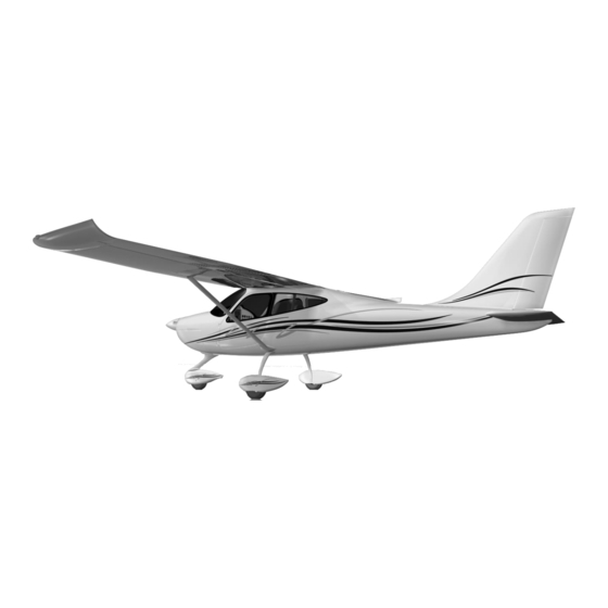
P2008 TC Flight Manual SECTION 1 GENERAL 1.1 Introduction The P2008 is an high wing, two-place, single-engine airplane equipped with tricycle landing gear. It has metal wings and stabilator and composite fuselage and vertical stabilizer. It is an ASTM compliant airplane designed to be flown by sport pilot rated pilots as well as higher rated pilots. - Page 13 P2008 TC Flight Manual THREE VIEW DRAWING Figure 1-1 General Views Wing Span 9.00 m (29.5 ft) Length 6.93 m (22.7 ft) Tail height 2.46 m (8.1 ft) Propeller ground clearance 310 + 40 mm (12.2 +1.6 in) Minimum ground steering radius 5.50 m...
-
Page 14: Descriptive Data
P2008 TC Flight Manual 1.3 Descriptive Data 1.3.1 Airframe 1.3.1.1 Wing Wing Span 9.00 m (29.5 ft) Wing Area 12.16 m (130.9 ft Aspect Ratio Taper Ratio Wing chord 1.373 m (4.5 ft) 1.3.1.2 Fuselage Overall length 6.93 m (22.7 ft) Overall width 1.20 m (3.9 ft) -
Page 15: Allowed Propellers
P2008 TC Flight Manual 1.4.2 Allowed Propellers Manufacturer Sensenich Model 3B0R5R68C Number of blades Diameter 1730 (68'') (no reduction permitted) Type Fixed - ground adjustable pitch Spacer B-1805-81 TECNAM Spacer Manufacturer MT Propeller Model MTV-33-1-A/175-200 Number of blades Diameter 1.75 m... -
Page 16: Fuel
P2008 TC Flight Manual 1.4.5 Fuel Fuel grade: Auto fuel Min. RON 95 (AKI 91 Premium USA) EN 228 Premium EN 228 Premium Plus Avgas 100LL Fuel tanks 2 integral wing tanks Capacity of each 52 liters (13.7 gal) wing tank Total capacity 104 liters (27.5 gal) -
Page 17: Interior
P2008 TC Flight Manual Flaps, Hydraulic Disc Brakes with Parking Brake and toe brakes on both seats, Left and Right Fuel Selector Valve, Direct Nose Wheel Steering (or pivoting NLG with differential breaking system) 1.6.5 Interior Adjustable Pilot and Copilot Seats, reclining for baggages compartement access, Acoustic Cabin Soundproofing,... -
Page 18: Airframe
P2008 TC Flight Manual 1.7 Airframe 1.7.1 Wing The wing is constructed of a central light alloy torque box; an aluminum leading edge is attached to the front spar while flap and aileron are hinged to rear spar. Flaps are constructed of a center spar to which front and rear ribs are joined; wrap- around aluminum skin panels cover the flap structure. -
Page 19: Instrument Panel
P2008 TC Flight Manual 1.7.5 Instrument Panel The instrument panel is of conventional type, allowing space for a broad range of equipment. DYNO N AVIO N IC S EM S-D10 Fig. 1-2 Instrument Panel 1.7.6 Cabin Heat / Defrost The cabin heat control knob (if available) is positioned on the lower of the instrument panel; when knob is pulled fully outward, cabin receives maximum hot air. -
Page 20: Doors
P2008 TC Flight Manual 1.7.9 Doors Standard doors feature a composite frame supporting a clear or tinted window. An internal safety latch mechanism is positioned in proximity of door's upper edge and must be used before flight to secure door. Mechanism rotates, before flight, to engage doorframe to cabin composite frame. -
Page 21: Powerplant
The Sensenich 2 or 3 blades propellers are also allowed to be mounted with the Sensenich provided installation kit for Tecnam. For Propeller installation see the manufacturer’s AMM P/N 2A0 (2 Blades) and 3B0R5 / 3B0R5-FD (3 Blades). The propeller pitch must be always set following Tecnam related Job Card N° 448 (Sensenich 2/3 Blades Installation and Settings) to ensure the pitch will not allow the airplane to fly over the maximum legal 120 KCAS and in order to avoid overspeeds which could damage the engine. -
Page 22: Fuel System
P2008 TC Flight Manual The MT Propeller MTV-33-1 can also be installed on P2008 A/C. It is a hydraulic constant speed propeller, of composite fibre construction with stainless steel leading edge for all weather operation. More information on the manufacturer and the propellercan be found at http://www.mt-propeller.com. -
Page 23: Electrical System
P2008 TC Flight Manual 1.9 Electrical System The aircraft's electrical system consists of a 12 VoltDC circuit controlled by a Master switch located on the instrument panel. An integrated AC generator provides electricity and a 12 Volt battery placed in the fuselage or in the engine compartment. -
Page 24: Voltmeter
P2008 TC Flight Manual 1.9.2 Voltmeter The voltmeter indicates voltage on the bus bar. The normal range is from 12 to 14 volts. There is a red radial line at 10 volts. 1.9.3 Oil temperature Temperatures are read in degrees Celsius. The oil temperature indicator has a green normal operating range, yellow caution ranges, and two red lines. -
Page 25: External Lights
P2008 TC Flight Manual 1.9.9 External Lights Typical exterior lighting consists of: Landing light Tail Strobe Light Navigation lights Wing Strobe Lights 1.9.9.1 Navigation Lights Navigation lights are installed on the wing tips and (optionally) on top of vertical stabilizer. A single switch located on instrument panel controls all navigation lights. -
Page 26: Pitot And Static Pressure Systems
P2008 TC Flight Manual 1.10 Pitot and Static Pressure Systems The airspeed indicator system for the aircraft is shown below. On the left wing’s strut the Pitot tube (1) while on the fuselage’s sides there are two static ports (2). Two flexible hoses (3) feed the airspeed indicator (4), the altimeter (5) and the VSI (6) on the instrument panel. -
Page 27: Landing Gear
P2008 TC Flight Manual 1.11 Landing Gear The main landing gear consists of two special steel spring-leaf struts positioned crossways to fuselage for elastic cushioning of landing loads. The two steel spring-leaf struts are attached to the fuselage underside via the main girder. -
Page 28: Brake System
P2008 TC Flight Manual 1.11.1 Brake System Figure 7-2 shows the brake system schematic diagram. The left and right wheel brakes are independent systems. The system has a reservoir (4) on the co-pilot’s brake pedals (1). The reservoir is directly connected to the brake master cylinders (3). Two flexible hoses connect the master cylinders on the co-pilot’s brake pedals to the master cylinders on the pilot’s brake pedals. -
Page 29: Section 2 Operating Limitations
P2008 TC Flight Manual SECTION 2 OPERATING LIMITATIONS 2 Introduction Section 2 includes operating limitations, instrument markings, and basic placards necessary for safe operation of the P2008, its engine, standard systems and standard equipment. 2.1.1 Airspeed Limitations Airspeed limitations and their operational significance are shown below:... -
Page 30: Powerplant Limitations
P2008 TC Flight Manual 2.1.3 Powerplant Limitations The following table lists operating limitations for aircraft installed engine: Engine manufacturer: Bombardier Rotax GmbH. Engine model: 914 UL Maximum power: (see table below) Max Power Max rpm. Time max. kW (hp) rpm prop.(engine) (min) 84.5 (113) -
Page 31: Lubricant
P2008 TC Flight Manual 2.1.8 Lubricant Viscosity Use viscosity grade oil as specified in the following table: Warning Admissible pressure for cold start is 7 bar maximum for short periods Warning Use of Aviation Grade Oil with or without additives is not permitted 2.1.9 Coolant... -
Page 32: Approved Fuel
P2008 TC Flight Manual Warning Compensate for uneven fuel tank levels by closing the fuel valve on the tank with more fuel making sure that one fuel valve is in the on position at all times. 2.1.12 Approved Fuel AVGAS 100LL Min. -
Page 33: Approved Maneuvers
P2008 TC Flight Manual 2.1.17 Approved Maneuvers This aircraft is intended for non-aerobatic operation only. Non-aerobatic operation includes: Any maneuver pertaining to “normal” flight Stalls (except whip stalls) Lazy eights Chandelles Turns in which the angle of bank is not more than 60°... -
Page 34: Day Vfr
P2008 TC Flight Manual 2.1.21 Day VFR The airplane, in standard configuration, is approved only for day VFR operations under VMC: Altimeter Airspeed Indicator Compass Fuel Gauges Oil Pressure Indicator Oil Temp. Indicator ... -
Page 35: Section 3 Weight & Balance
P2008 TC Flight Manual SECTION 3 WEIGHT & BALANCE 3 Introduction This section describes the procedure for establishing the basic empty weight and moment of the aircraft. Loading procedure information is also provided. 3.1 Aircraft weighing procedures 3.1.1 Preparation ... -
Page 36: Weighing Report
P2008 TC Flight Manual 3.2 Weighing report Model P2008____________S/N ________________ Date ________________ Datum Reference line W2=WL+WR Datum: Propeller support flange w/o spacer. - Equipment list, date: _____ meters Nose wheel weight W Plumb bob distance LH wheel LH wheel weight... -
Page 37: Distances From The Datum
P2008 TC Flight Manual 3.2.2 Distances from the datum The mean distances of the occupants, baggage and fuel from the datum are: Figure 3-1... -
Page 38: Weight And Balance
P2008 TC Flight Manual 3.3 Weight and Balance In order to compute the weight and balance of this aircraft, we have provided the following loading charts. This will reduce the amount of math you need. To compute weight and balance use the formula: Weight * Arm = Moment. -
Page 39: Loading
P2008 TC Flight Manual To compute weight and balance: Get moments from loading charts Obtain the empty weight and moment from the most recent weight and balance Insert the weights and the moments for fuel, occupants and baggage from the previous chart... -
Page 40: Section 4 Performance
P2008 TC Flight Manual SECTION 4 PERFORMANCE 4 Introduction This section provides all necessary data for accurate and comprehensive planning of flight activity from takeoff to landing. Data reported in graphs and/or tables were determined using: “Flight test data” with conditions as prescribed by ASTM and bilateral agreements ... -
Page 41: Airspeed Indicator System Calibration
P2008 TC Flight Manual 4.2 Airspeed Indicator System Calibration Graph shows calibrated airspeed V as a function of indicated airspeed V Fig. 4-1 Calibrated vs. Indicated Airspeed flaps full deflected The following formula gives the CAS with the CAS = 1.0611xIAS – 7.7222... -
Page 42: Icao Chart
P2008 TC Flight Manual 4.3 ICAO Chart Fig. 4-2 ICAO C HART... -
Page 43: Stall Speeds
P2008 TC Flight Manual 4.4 Stall Speeds Conditions: - Weight 600 kg (1320 lbs) - Throttle: idle - No ground effect NOTE Altitude loss during conventional stall recovery as demonstrated during test flights is approximately 200ft with banking under 30°. -
Page 44: Crosswind
P2008 TC Flight Manual 4.5 Crosswind Maximum demonstrated crosswind velocity is 15 knots Fig. 4-3 Crosswind chart... -
Page 45: Takeoff Performance
P2008 TC Flight Manual 4.6 Takeoff Performance Weight = 600 kg Corrections Headwind: - 5m for each kt (16 ft/kt) Take-Off (15°) Flaps: Tailwind: + 15m for each kt (50ft/kt) Speed at Lift-Off = 48 KIAS Paved Runway: - 6% to Ground Roll... - Page 46 P2008 TC Flight Manual Weight = 550 kg Corrections Headwind: - 5m for each kt (16 ft/kt) Take-Off (15°) Flaps: Tailwind: + 15m for each kt (50ft/kt) Speed at Lift-Off = 48 KIAS Paved Runway: - 6% to Ground Roll...
- Page 47 P2008 TC Flight Manual Weight = 500 kg Corrections Headwind: - 5m for each kt (16 ft/kt) Take-Off (15°) Flaps: Tailwind: + 15m for each kt (50ft/kt) Speed at Lift-Off = 48 KIAS Paved Runway: - 6% to Ground Roll...
-
Page 48: Landing Distance
P2008 TC Flight Manual 4.7 Landing Distance Weight = 600 kg Corrections Headwind: - 5m for each kt (16 ft/kt) Flaps: Land (40°) Tailwind: + 15m for each kt (50ft/kt) Short Final Approach Speed = 52 KIAS Paved Runway: - 2% to Ground Roll Throttle Levers: Idle Runway slope: - 2.5% to Ground Roll for each +1%... - Page 49 P2008 TC Flight Manual Weight = 550 kg Corrections Headwind: - 5m for each kt (16 ft/kt) Flaps: Land (40°) Tailwind: + 15m for each kt (50ft/kt) Short Final Approach Speed = 52 KIAS Paved Runway: - 2% to Ground Roll Throttle Levers: Idle Runway slope: - 2.5% to Ground Roll for each +1%...
- Page 50 P2008 TC Flight Manual Weight = 500 kg Corrections Headwind: - 5m for each kt (16 ft/kt) Flaps: Land (40°) Tailwind: + 15m for each kt (50ft/kt) Short Final Approach Speed = 52 KIAS Paved Runway: - 2% to Ground Roll Throttle Levers: Idle Runway slope: - 2.5% to Ground Roll for each +1%...
-
Page 51: Climb Performance
P2008 TC Flight Manual 4.8 Climb Performance CLIMB RATE IN CLEAN CONFIGURATION ONDITIONS Flap: 0° Engine: MCP = 78 KIAS [77KCAS] Fig. 4-5 C LIMB Example: Given Find O.A.T. = 17°C Rate of climb = 1095 ft/min... -
Page 52: Cruise
P2008 TC Flight Manual 4.9 Cruise Maximum takeoff weight = 600 kg (1320 lbs) Fuel tanks 2x52 liters (13.7 gal) (less the unusable fuel = 1.1gal) ALL ENDURANCE DATA (HOURS AND n.m.) ARE GIVEN WITH A RESERVE OF 30’ (FOR EXAMPLE: THE FIRST ROW INDICATES A RANGE OF 7.1hrs + 0.5hr RESERVE) OAT: +15°C... - Page 53 P2008 TC Flight Manual 8000 ft OAT: -1°C Pressure altitude H Power Engine Speed Speed Consumption Endurance (hrs) Range (N.m.) (including 30’ reserve) setting KTAS (gal/h) 4300 4800 5000 5500 110% 5800 10000 OAT: -5°C Pressure altitude H Power Engine Speed...
-
Page 54: Balked Landing
P2008 TC Flight Manual 4.10 Balked Landing RATE OF CLIMB: BALKED LANDING ONDITIONS Maximum weight = 600 kg (1320 lb) Engine: MTOP Flaps: 35° 15 flaps = 66 KIAS [62 KCAS] RC ~ 1000 ft/min NOTE During balked landing maneuver, flaps should be retracted immediately after applying full power. -
Page 55: Section 5 Emergency Procedures
P2008 TC Flight Manual SECTION 5 EMERGENCY PROCEDURES 5 Introduction Section 6 includes checklists and detailed procedures to be used in the event of emergencies. Emergencies caused by a malfunction of the aircraft or engine are extremely rare if appropriate maintenance and pre-flight inspections are carried out. -
Page 56: Engine Failures
P2008 TC Flight Manual 5.1 Engine Failures If an emergency arises, the basic guidelines described in this section should be considered and applied as necessary to correct the problem. 5.1.1 Engine Failures on Ground 5.1.1.1 ENGINE FAILURE DURING TAKEOFF RUN Throttle: .................. -
Page 57: Smoke And Fire
P2008 TC Flight Manual 5.1.2.4 LOW OIL PRESSURE Throttle Lever:................REDUCE Minimum pratical Oil temperature: ................. CHECK If the temperature tends to increase: If the temperature is within the green arc: ......... LAND as soon as possible If the temperature is out of the green arc: ........LAND as soon as possible and be alert for impending engine failure 5.1.2.5... -
Page 58: Engine Fire In-Flight
P2008 TC Flight Manual 5.2.3 Engine Fire in-flight Cabin heat: ................OFF Fuel selector valve: ..............OFF Throttle: ..................FULL IN until the engine stops running Cabin vents: ................OPEN Ignition Switches: ..............OFF Do not attempt an in-flight restart Procedure for a forced landing: .......... -
Page 59: Recovery From Unintentional Spin
P2008 TC Flight Manual NOTE Align the airplane on the opposite side of runway to the side with the defective tire to compensate for change in direction, which is to be expected during final rolling. Touchdown with the GOOD TIRE FIRST and hold aircraft with the flat tire off the ground as long as possible. -
Page 60: Failures Indicated On The Annunciator Panel
P2008 TC Flight Manual 5.6 Failures indicated on the annunciator panel 5.6.1 ALTERNATOR LIGHT Alternator (ALT) light may illuminate for a faulty alternator. If the Alternator light illuminates proceed as follows: LAND as soon as possible Continue flight on battery power alone; the battery is capable of supplying the electrical system for about 20 minutes with normal flight electric loads including operation of flap and trim. -
Page 61: Trim System Failure
P2008 TC Flight Manual 5.7 Trim System Failure 5.7.1 LOCKED CONTROL In case the trim control should not respond, act as follows: Fuses / breakers ................. CHECK LH/RH switch ................CHECK for correct position Airspeed ..................Adjust speed to control aircraft without excessive stick force Land aircraft as soon as possible 5.8 Other Emergencies... -
Page 62: Section 6 Normal Procedures
P2008 TC Flight Manual SECTION 6 NORMAL PROCEDURES 6 Introduction Section 6 contains checklists and the procedures for normal operation. 6.1 Removing and Reinstalling the Engine Cowling 6.1.1 Upper Cowling Parking brake: .........ON Fuel selector valve: ......OFF Ignition Switches: ......OFF Master switch: .........OFF... -
Page 63: Checklist Procedures
P2008 TC Flight Manual 6.2 Checklist Procedures 6.2.1 Pre-Flight Inspection Before each flight, it is necessary to carry out a complete inspection of the aircraft starting with an external inspection followed by an internal inspection. 6.2.1.1 Cabin Inspection All required paperwork: ............ONBOARD Weight and balance: .............. - Page 64 P2008 TC Flight Manual 6.2.1.2 External Inspection It is best to follow to follow the external inspection in the station order outlined in fig. 6-1 so nothing is missed. Visual inspection is defined as follows: check for defects, cracks, detachments, excessive play, and unsafe or improper installation as well as for general condition.
- Page 65 P2008 TC Flight Manual N. Right side fuel filler cap: CHECK visually for desired fuel level and secure O. Nose wheel strut and tire: CHECK inflation 32 PSI (2.2 bar); tire condition and condition of rubber shock absorber discs. Check the right static port for obstructions.
- Page 66 P2008 TC Flight Manual Master switch: ................ON Throttle: ..................IDLE Choke: ..................AS NEEDED Propeller area: ................CLEAR WARNING Check to insure no person or object is present in the area close to propeller Strobe light: ................ON Ignition Switches: ..............ON Master Switch:................
- Page 67 P2008 TC Flight Manual Trim: CENTER Seat belts: FASTENED Doors: CLOSED AND LOCKED Transponder (if installed): ALT 6.2.1.8 TAKEOFF AND CLIMB Parking brake: Taxi to line-up: Magnetic compass and DG: CHECK, SET Throttle: FULL NOTE Static RPM is approximately 5100 250 rpm...
- Page 68 P2008 TC Flight Manual Airspeed: 66 KIAS [62 KCAS] Flaps position: LN / 35 degrees Airspeed: 66 KIAS [62 KCAS] Trim: ADJUST Above 300’ AGL: Flaps: RETRACT Establish Vy clean: 78 KIAS [77KCAS] Trim: ADJUST After takeoff checklist: .............. COMPLETE 6.2.1.12 AFTER LANDING...
-
Page 69: Section 7 Ground Handling & Service
P2008 TC Flight Manual SECTION 7 GROUND HANDLING & SERVICE 7 Introduction This section contains factory-recommended procedures for proper ground handling and routine care and servicing. It also identifies certain inspection and maintenance requirements, which must be followed if the aircraft is to retain its new-plane performance and dependability. -
Page 70: Cleaning And Care
P2008 TC Flight Manual 7.3.6 Cleaning and Care To clean painted surfaces, use a mild detergent such as shampoo normally used for car finish; use a soft cloth for drying. The plastic windshield and windows should never be dusted when dry; use lukewarm soapy water and dry using chamois only. -
Page 71: Placards & Markings
P2008 TC Flight Manual Section 8 PLACARDS & MARKINGS 8 PLACARDS & MARKINGS 8.1.1 Magnetic compass compensation table To compensate the deviation errors of the magnetic compass, the following correction table is located just below the compass: Steer Steer DATE... -
Page 72: Trim Switch
P2008 TC Flight Manual 8.1.4 Trim switch The trim shunt control is located on the upper left area of the instrument panel alternatively allocating trim control to either Rh or Lh control stick. The following placard (25x14mm) is positioned just above of it. -
Page 73: Choke
P2008 TC Flight Manual 8.1.8 Choke Located above the choke lever: 8.1.9 Generator light A generator warning light is located on the upper/right side of the instrument panel and it is marked with the following label. 8.1.10 Fuel selector valve Fuel shutoff valve is located on central section of cockpit panel. -
Page 74: Baggage Compartment
P2008 TC Flight Manual 8.1.11 Baggage compartment A placard (30x50mm) indicating the maximum weight and to fasten the baggage’s retain harnesses, is present visible into the baggage compartment. 8.1.12 Oil tank reservoir On the oil tank reservoir is present one placards (70x70) indicating the type and quantity of engine’s oil stored into the reservoir, see placard and its installation in par. -
Page 75: Brake Oil Reservoir
P2008 TC Flight Manual 8.1.14 Brake oil reservoir On the cap of the brake’s oil tank, is a placard indicating the type of oil that must be used. 8.1.15 Tire pressures On each steel spring leaf is a placard indicating the main tires inflating pressure (18x6mm):... -
Page 76: Static Port
P2008 TC Flight Manual 8.1.18 Static port On each static port is locate a placard diam 20mm: 8.1.19 Fuel Tank Next each fuel tank is the following placard (40x100 mm) 8.1.20 Limitation Placards Next to the airspeed indicator is the following placard (6x52mm). -
Page 77: Supplement List
SUPPLEMENT LIST 9 SUPPLEMENT LIST 9.1 Introduction This Section concerns the supplemental manuals of additional (or optional) instrumentation equipping the P2008 TC and/or information and limitations related to installed equipment configuration or needed to fit local national rules. 9.2 Supplements list... - Page 78 P2008 TC Flight Manual INTENTIONALLY LEFT BLANK...
- Page 79 P2008 TC Flight Manual SUPPLEMENT No. S1 AIRSPEED INCREMENT Record of Revisions Any revisions to the present Manual, except actual weighing data, must be recorded in the following table. New or amended text in the revised pages will be indicated by a black vertical line in the left-hand margin;...
- Page 80 P2008 TC Flight Manual List of Effective Pages Page Date Page Date 25/11/2013 “ “ “ “ “ “ “ “ “ “ “ “ “...
- Page 81 P2008 TC Flight Manual Table of Contents SUPPLEMENT No. S1 AIRSPEED INCREMENT ....................... 1 Record of Revisions ..............................1 Log of Revisions ................................1 List of Effective Pages ..............................2 Table of Contents ............................... 3 Introduction ................................5 Section 1 –General..............................7 Section 2 –Operating Limitations ..........................
- Page 82 P2008 TC Flight Manual INTENTIONALLY LEFT BLANK...
- Page 83 Airspeeds increment in subject. It is the owner’s responsibility to replace the mentioned pages in accordance with the instructions herein addressed section by section. NOTE: TECNAM reminds that flights in yellow arcs should be only performed in smooth with caution.
- Page 84 P2008 TC Flight Manual INTENTIONALLY LEFT BLANK...
- Page 85 P2008 TC Flight Manual Supplement S1: pages replacement instructions Section 1 –General Refer to Basic AFM Section 1.
- Page 86 P2008 TC Flight Manual INTENTIONALLY LEFT BLAN...
- Page 87 P2008 TC Flight Manual Supplement S1: pages replacement instructions Section 2 –Operating Limitations Apply following pages replacement procedure: Supplement S1 – Basic AFM LIMITATIONS page Section 2 page REPLACES Page 29 REPLACES Page 30...
- Page 88 P2008 TC Flight Manual INTENTIONALLY LEFT BLANK...
- Page 89 P2008 TC Flight Manual SECTION 2 OPERATING LIMITATIONS 2. Introduction Section 2 includes operating limitations, instrument markings, and basic placards necessary for safe operation of the P2008, its engine, standard systems and standard equipment. 2.1.1 Airspeed Limitations Airspeed limitations and their operational significance are shown below:...
- Page 90 P2008 TC Flight Manual 2.1.3 Powerplant Limitations The following table lists operating limitations for aircraft installed engine: Engine manufacturer: Bombardier Rotax GmbH. Engine model: 914 UL Maximum power: (see table below) Max Power Max rpm. Time max. kW (hp) rpm prop.(engine) (min) Max.
- Page 91 P2008 TC Flight Manual Supplement S1: pages replacement instructions Section 3 – Weight & Balance Refer to Basic AFM Section 3.
- Page 92 P2008 TC Flight Manual INTENTIONALLY LEFT BLAN...
- Page 93 P2008 TC Flight Manual Supplement S1: pages replacement instructions Section 4 –Performance Apply following pages replacement procedure: Supplement S1 – Basic AFM Performance page Section 4 page REPLACES Page 41 REPLACES Page 42 Page 43 REPLACES REPLACES Page 44...
- Page 94 P2008 TC Flight Manual INTENTIONALLY LEFT BLANK...
- Page 95 P2008 TC Flight Manual 4.4 Airspeed Indicator System Calibration Graph shows calibrated airspeed V as a function of indicated airspeed V IAS-CAS kts FLAP CLEAN Fig. 4-1 Calibrated vs. Indicated Airspeed flaps full deflected The following formula gives the CAS with the...
- Page 96 P2008 TC Flight Manual 4.5 ICAO Chart Fig. 4-2 ICAO C HART...
- Page 97 P2008 TC Flight Manual 4.6 Stall Speeds Conditions: - Weight 600 kg (1320 lbs) - Throttle: idle - No ground effect NOTE Altitude loss during conventional stall recovery as demonstrated during test flights is approximately 200ft with banking under 30°.
- Page 98 P2008 TC Flight Manual 4.7 Crosswind Maximum demonstrated crosswind velocity is 15 knots Fig. 4-3 Crosswind chart...
-
Page 99: Record Of Revisions
P2008 TC Flight Manual SUPPLEMENT No. S2 MTV-33-1 VARIABLE PITCH PROPELLER Record of Revisions Any revisions to the present Manual, except actual weighing data, must be recorded in the following table. New or amended text in the revised pages will be indicated by a black vertical line in the left-hand margin;... -
Page 100: List Of Effective Pages
P2008 TC Flight Manual List of Effective Pages Page Date Page Date 2/8/2017 “ “ “ “ “ “ “ “ “ “ “ “ “ “... - Page 101 P2008 TC Flight Manual Table of Contents Record of Revisions ..............................1 Log of Revisions ................................1 List of Effective Pages ..............................2 Table of Contents ............................... 3 Introduction ................................5 Section 1 –General..............................7 1.4.2 Allowed Propellers ............................ 15 1.4.3...
- Page 102 P2008 TC Flight Manual INTENTIONALLY LEFT BLANK...
- Page 103 MTV-33-1 propeller. It is the owner’s responsibility to replace the mentioned pages in accordance with the instructions herein addressed section by section. NOTE: TECNAM reminds that flights in yellow arcs should be only performed in smooth with caution.
- Page 104 P2008 TC Flight Manual INTENTIONALLY LEFT BLANK...
-
Page 105: Section 1 -General
P2008 TC Flight Manual Supplement S2: pages replacement instructions Section 1 –General Apply following pages replacement procedure: Supplement S2 – Basic AFM GENERAL pages Section 1 pages MT15 REPLACE MT22 REPLACES... - Page 106 P2008 TC Flight Manual INTENTIONALLY LEFT BLANK...
- Page 107 P2008 TC Flight Manual 1.4.2 Allowed Propellers GT Tonini Sensenich MT Propeller Manufacturer: Model: GT-2/173/VRR-FW101 2A0R5R70EN (2 Blades) - MTV-33-1-A/175-200 3B0R5R68C (3 Blades) 2/3 Blades Number of blades: 1730 mm (68’’) 1778 mm (70”) (2 Blades) - 1750 mm (69”) Diameter: 1730 mm (68”) (3 Blades)
- Page 108 P2008 TC Flight Manual The MT Propeller MTV-33-1 can also be installed on P2008 A/C. It is a hydraulic constant speed propeller, of composite fiber construction with stainless steel leading edge for all weather operation. More information on the manufacturer and the propeller can be found at http://www.mt-propeller.com.
-
Page 109: Section 2 - Operating Limitations
P2008 TC Flight Manual Supplement S2: pages replacement instructions Section 2 – Operating Limitations Apply following pages replacement procedure: Supplement S2 – Basic AFM LIMITATIONS pages Section 2 pages MT31 REPLACES... - Page 110 P2008 TC Flight Manual 3.4.2 Lubricant Viscosity Use viscosity grade oil as specified in the following table: Warning Admissible pressure for cold start is 7 bar maximum for short periods Warning Use of Aviation Grade Oil with or without additives is not permitted 3.4.3 Coolant...
-
Page 111: Section 3 - Weight & Balance
P2008 TC Flight Manual Supplement S2: pages replacement instructions Section 3 – Weight & Balance Refer to Basic AFM Section 3. -
Page 112: Section 4 -Performance
P2008 TC Flight Manual Supplement S2: pages replacement instructions Section 4 –Performance Apply following pages replacement procedure: Supplement S1 – Basic AFM Performance pages Section 4 pages A45 thru A47 REPLACE 45 thru 47 A51 thru A53 51 thru 53... - Page 113 P2008 TC Flight Manual 4.6 Takeoff Performance Weight = 600 kg Corrections Headwind: - 5m for each kt (16 ft/kt) Take-Off (15°) Flaps: Tailwind: + 15m for each kt (50ft/kt) Speed at Lift-Off = 48 KIAS Paved Runway: - 6% to Ground Roll...
- Page 114 P2008 TC Flight Manual Weight = 550 kg Corrections Headwind: - 5m for each kt (16 ft/kt) Take-Off (15°) Flaps: Tailwind: + 15m for each kt (50 ft/kt) Speed at Lift-Off = 48 KIAS Paved Runway: - 6% to Ground Roll...
- Page 115 P2008 TC Flight Manual Weight = 500 kg Corrections Headwind: - 5m for each kt (16 ft/kt) Take-Off (15°) Flaps: Tailwind: + 15m for each kt (50ft/kt) Speed at Lift-Off = 48 KIAS Paved Runway: - 6% to Ground Roll...
- Page 116 P2008 TC Flight Manual 4.8 Climb Performance CLIMB RATE IN CLEAN CONFIGURATION ONDITIONS Flap: 0° Engine: MCP = 78 KIAS [77KCAS] Fig. 4-5 C LIMB Example: Given Find O.A.T. = 17°C Rate of climb = 1095 ft/min...
- Page 117 P2008 TC Flight Manual 4.9 Cruise Maximum takeoff weight = 600 kg (1320 lbs) Fuel tanks 2x52 liters (13.7 gal) (less the unusable fuel = 1.1gal) ALL ENDURANCE DATA (HOURS AND n.m.) ARE GIVEN WITH A RESERVE OF 30’ (FOR EXAMPLE: THE FIRST ROW INDICATES A RANGE OF 7.1hrs + 0.5hr RESERVE) OAT: +15°C...
- Page 118 P2008 TC Flight Manual 8000 ft OAT: -1°C Pressure altitude H Power Propeller Speed Consumption Endurance (hrs) Range (N.m.) (including 30’ reserve) setting KTAS (gal/h) 1770 1976 2058 2264 110% 2388 10000 OAT: -5°C Pressure altitude H Power Propeller Speed...
- Page 119 P2008 TC Flight Manual Supplement S2: pages replacement instructions Section 5 – Emergency Procedures Refer to Basic AFM Section 5.
-
Page 120: Section 6 - Normal Procedures
P2008 TC Flight Manual Supplement S2: pages replacement instructions Section 6 – Normal Procedures Refer to Basic AFM Section 6. -
Page 121: Section 7 - Ground Handling & Service
P2008 TC Flight Manual Supplement S2: pages replacement instructions Section 7 – Ground Handling & Service Refer to Basic AFM Section 7. -
Page 122: Section 8 - Placards & Markings
P2008 TC Flight Manual Supplement S2: pages replacement instructions Section 8 – Placards & Markings Refer to Basic AFM Section 8. - Page 123 P2008 TC Flight Manual Feedback Form Send your comments to: In the USA: Tecnam North America Headquarters 7511 Airfield Drive, Box 8 Richmond, VA 23237 1-888-359-4682 www.tecnam.net info@tecnam.net (770) 309-4155 Italian Address: www.tecnam.com COSTRUZIONI AERONAUTICHE TECNAM s.r.l. Via Maiorise 81043 Capua (CE) - ITALY ...
- Page 124 P2008 TC Flight Manual INTENTIONALLY LEFT BLANK...
Need help?
Do you have a question about the P2008 TC and is the answer not in the manual?
Questions and answers