Table of Contents
Advertisement
Quick Links
M
ANUFACTURER
A
IRCRAFT MODEL
T
YPE CERTIFICATION
S
ERIAL NUMBER
B
UILD YEAR
R
EGISTRATION MARKINGS
This manual contains information to be furnished to the pilot as required by EASA
in addition to further information supplied by manufacturer.
This manual must always be present on board the aircraft.
The aircraft is to be operated in compliance with information and limitations
contained herein.
Sections 2, 3, 4, 5 are approved by EASA: n° 10030344 on 11.06.2010
Section 9 (supp.1) is approved by EASA: n° 2004-1787 on 02.03.2004
Section 9 (supp. 2) is approved by EASA: n° 2004-6324 on 17.06.2004.
Section 9 (supp.3) is approved under DOA privileges: n° MOD92/51.10.06.2009
Section 9 (supp.4) is approved under DOA privileges: n° MOD92/52.10.06.2009
Section 9 (supp.5) is approved under DOA privileges: n° MOD92/53.10.06.2009
th
Date: Issue 3, 25
F
LIGHT
FLIGHT MANUAL
Doc. n° 92/61 Issue n°3: 25
Revision No.0
P92-JS
:
COSTRUZIONI AERONAUTICHE
P92-JS
:
: n° EASA A.412 (SO/A-340)
: ....................................................................
: .........................................................................
: .......................................................
May 2010
M
ANUAL
th
May 2010
TECNAM
P92-JS
I N T R O D U C T I O N
S.r.l.
i-1
Advertisement
Chapters
Table of Contents

Related Manuals for Tecnam P92-JS


Summary of Contents for Tecnam P92-JS
-
Page 1: Flight Manual
P92-JS LIGHT ANUAL I N T R O D U C T I O N FLIGHT MANUAL Doc. n° 92/61 Issue n°3: 25 May 2010 Revision No.0 P92-JS TECNAM S.r.l. COSTRUZIONI AERONAUTICHE ANUFACTURER P92-JS IRCRAFT MODEL : n° EASA A.412 (SO/A-340) YPE CERTIFICATION : ............….. - Page 2 P92-JS LIGHT MANUAL I N T R O D U C T I O N RECORD OF REVISIONS Any revisions to the present Manual, except actual weighing data, must be recorded in the following table and, in case of approved Sections, endorsed by the responsible airworthiness authority.
- Page 3 P92-JS LIGHT ANUAL I N T R O D U C T I O N LIST OF EFFECTIVE PAGES Section Pages Revision Section 0 Pages 1 thru 4 Rev 0 Section 1 Pages 1 thru 12 Rev 0 Section 2...
- Page 4 P92-JS LIGHT MANUAL I N T R O D U C T I O N TABLE OF CONTENTS General Section 1 Limitations Section 2 Emergency procedures Section 3 Normal procedures Section 4 Performance Section 5 Weight & Balance / Equipment list...
-
Page 5: Table Of Contents
P92-JS S E C T I O N 1 LIGHT MANUAL GENERAL SECTION 1 GENERAL TABLE OF CONTENTS INTRODUCTION ...................... 2 CERTIFICATION BASIS ..................2 WARNINGS - CAUTIONS - NOTES ................ 2 THREE-VIEW DRAWING ..................3 DESCRIPTIVE DATA ....................4 CONTROL SURFACES TRAVEL LIMITS .............. -
Page 6: Introduction
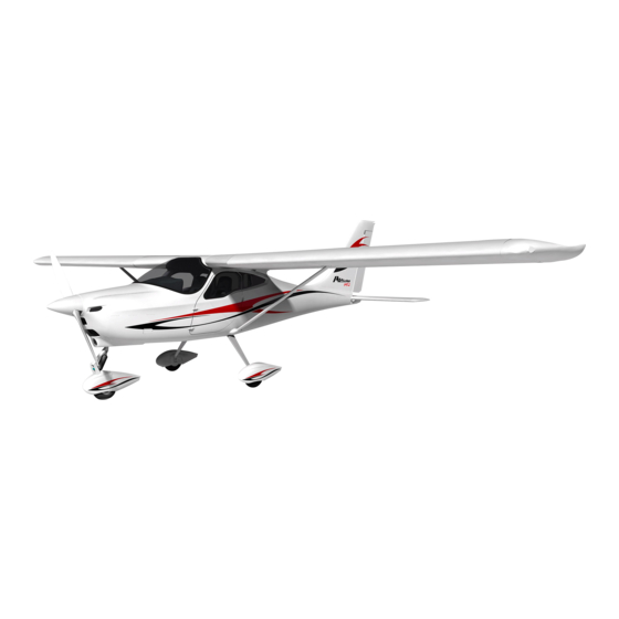
LIGHT MANUAL GENERAL INTRODUCTION The P92-JS is a twin seat single engine aircraft with a strut-braced rectangular high wing, fixed main landing gear and steerable nosewheel. This Flight Manual has been prepared to provide pilots and instructors with information for the safe and efficient operation of this aircraft. -
Page 7: Three-View Drawing
P92-JS S E C T I O N 1 LIGHT MANUAL GENERAL THREE-VIEW DRAWING NOTE Dimensions shown refer to aircraft weight of 550kg (and 600 kg) and normal operating tire pressure. Propeller ground clearance 320mm Propeller ground clearance with deflated front tire and nosewheel shock absorber compressed by 102mm ... -
Page 8: Descriptive Data
P92-JS S E C T I O N 1 LIGHT MANUAL GENERAL DESCRIPTIVE DATA WING For 550 kg For 600 kg MTOW MTOW Wing span: 8.7 m 8.7 m Wing chord 1.4 m 1.4 m Wing surface 12 m 12 m Wing loading 45.8 kg/m... -
Page 9: Engine
P92-JS S E C T I O N 1 LIGHT MANUAL GENERAL ENGINE Manufacturer: Bombardier-Rotax GmbH Model 912 S2 Certification basis FAR 33 Amendment 15 Austrian Type- n° TW 9-ACG of 27 Nov. 1998 Certification No. Type: 4 cylinder horizontally-opposed twins with overall displacement of 1352 c.c., mixed... -
Page 10: Fuel
P92-JS S E C T I O N 1 LIGHT MANUAL GENERAL FUEL High octane gasoline DIN 51600, Fuel grade: O-NORM 1103 (red) Unleaded gasoline DIN 51603, O-NORM 1101 AVGAS 100LL (see Section 2.9) Fuel tanks: 2 wing tanks integrated within the wing's leading edge with fuel strainer located in engine cowling. -
Page 11: Maximum Certified Weights
P92-JS S E C T I O N 1 LIGHT MANUAL GENERAL For 550 kg For 600 kg MTOW MTOW MAXIMUM CERTIFIED WEIGHTS Maximum take-off weight: 550 kg 600 kg Maximum landing weight: 550 kg 600 kg Maximum baggage weight... -
Page 12: Abbreviations And Terminology
P92-JS S E C T I O N 1 LIGHT MANUAL GENERAL ABBREVIATIONS AND TERMINOLOGY GENERAL AIRSPEED TERMINOLOGY AND SYMBOLS KCAS Knots Calibrated Airspeed is indicated airspeed corrected for position and instrument error and expressed in knots. KIAS Knots Indicated Airspeed is the speed shown on the airspeed indicator and expressed in knots. - Page 13 P92-JS S E C T I O N 1 LIGHT MANUAL GENERAL METEOROLOGICAL TERMINOLOGY Outside Air Temperature is the free air static temperature expressed in degrees Celsius (°C). Standard Temperature is 15°C at sea level pressure altitude and decreased by 2°C for each 1000 ft of altitude.
- Page 14 P92-JS S E C T I O N 1 LIGHT MANUAL GENERAL WEIGHT AND BALANCE TERMINOLOGY Datum is an imaginary vertical plane from which all horizontal distances are measured for balance purposes. is the horizontal distance from the reference datum to the center of gravity (C.G.) of an item.
-
Page 15: Unit Conversion Chart
P92-JS S E C T I O N 1 LIGHT MANUAL GENERAL UNIT CONVERSION CHART ULTIPLYING YIELDS EMPERATURE Fahrenheit [°F] Celsius [°C] Celsius [°C] Fahrenheit [°F] ORCES 2.205... - Page 16 P92-JS S E C T I O N 1 LIGHT MANUAL GENERAL INTENTIONALLY LEFT BLANK I-12 Date: Issue 3: 25 May2010...
- Page 17 P92-JS S E C T I O N 2 LIGHT ANUAL LIMITATIONS SECTION 2 LIMITATIONS TABLE OF CONTENTS INTRODUCTION ...................... 2 AIRSPEED LIMITATIONS ..................2 AIRSPEED INDICATOR MARKINGS ..............3 POWERPLANT LIMITATIONS ................4 PROPELLER ......................5 POWERPLANT INSTRUMENT MARKINGS ............6 OTHER INSTRUMENT MARKINGS ..............
-
Page 18: Introduction
LIGHT ANUAL LIMITATIONS INTRODUCTION Section 2 includes operating limitations, instrument markings, and basic placards necessary for safe operation of the P92-JS, its engine, standard systems and standard equipment. NOTE Refer to section 9 for possible variations to: AIRSPEED LIMITATIONS Airspeed limitations and their operational significance are shown below:... -
Page 19: Airspeed Indicator Markings
Yellow and only in smooth air. Maximum speed for all operations. Red line For P92-JS with MTOW = 550kg the low limit of the white CAUTION arc is 1.1 V while the low limit of the green arc is 1.1V... -
Page 20: Powerplant Limitations
P92-JS S E C T I O N 2 LIGHT ANUAL LIMITATIONS POWERPLANT LIMITATIONS The following table lists operating limitations for aircraft installed engine: : Bombardier Rotax GmbH. NGINE MANUFACTURER : 912 S2 NGINE MODEL : (see table below) AXIMUM POWER Max Power Max RPM. -
Page 21: Propeller
P92-JS S E C T I O N 2 LIGHT ANUAL LIMITATIONS FUEL PRESSURE: 2.2 psi 5.8 psi VISCOSITY Use viscosity grade oil as specified in the following table: WARNING Use of Aviation Grade Oil with or without additives is not permitted COOLANT: Mixture: 80% concentrated antifreeze (e.g. -
Page 22: Powerplant Instrument Markings
P92-JS S E C T I O N 2 LIGHT ANUAL LIMITATIONS POWERPLANT INSTRUMENT MARKINGS Powerplant instrument markings and their color code significance are shown below: RED LINE GREEN ARC YELLOW ARC RED LINE Minimum limit Normal Caution Maximum INSTRUMENT... -
Page 23: Weights
P92-JS S E C T I O N 2 LIGHT ANUAL LIMITATIONS WEIGHTS 550 kg MTOW 600 kg MTOW Maximum takeoff weight 550 kg 600 kg Maximum landing weight 550 kg 600 kg Maximum zero fuel weight 550 kg 600 kg... -
Page 24: Approved Maneuvers
P92-JS S E C T I O N 2 LIGHT ANUAL LIMITATIONS APPROVED MANEUVERS This aircraft is certified in the CS-VLA category. CS-VLA applies to airplanes intended for non-aerobatic operation only. Non- aerobatic operation includes: Any maneuver pertaining to “normal” flight ... -
Page 25: Kinds Of Operation
P92-JS S E C T I O N 2 LIGHT ANUAL LIMITATIONS KINDS OF OPERATION The airplane, in standard configuration, is approved only for day VFR operation with terrain visual contact. Minimum equipment required is as follows: Altimeter ... -
Page 26: Maximum Passenger Seating
P92-JS S E C T I O N 2 LIGHT ANUAL LIMITATIONS MAXIMUM PASSENGER SEATING Only one passenger is allowed on board this aircraft. CROSSWIND LIMITATIONS Maximum allowed crosswind component is 15 Kts (refer to section 5 for further details). - Page 27 P92-JS S E C T I O N 3 LIGHT ANUAL EMERGENCY PROCEDURES SECTION 3 EMERGENCY PROCEDURES TABLE OF CONTENTS INTRODUCTION ...................... 2 ENGINE FAILURES ....................2 AIR START ........................ 4 SMOKE AND FIRE ....................4 GLIDE ........................5 LANDING EMERGENCIES ..................5 RECOVERY FROM UNINTENTIONAL SPIN ............
-
Page 28: Introduction
P92-JS S E C T I O N 3 LIGHT ANUAL EMERGENCY PROCEDURES INTRODUCTION Section 3 includes checklists and detailed procedures to be used in the event of emergencies. Emergencies caused by a malfunction of the aircraft or engine are extremely rare if appropriate maintenance and pre-flight inspections are carried out. - Page 29 P92-JS S E C T I O N 3 LIGHT ANUAL EMERGENCY PROCEDURES ENGINE FAILURE IMMEDIATELY AFTER TAKEOFF Speed 60 KIAS Locate landing area Throttle: idle (fully out) Fuel shutoff valves: OFF. Electric fuel pump: OFF Magnetos OFF. Flaps: as needed.
-
Page 30: Air Start
P92-JS S E C T I O N 3 LIGHT ANUAL EMERGENCY PROCEDURES AIR START Altitude: preferably below 4000 ft Carb heat: ON Fuel shutoff valves: both ON Electric fuel pump: ON Throttle: middle position Generator switch and Master switch: ON. -
Page 31: Glide
P92-JS S E C T I O N 3 LIGHT ANUAL EMERGENCY PROCEDURES ENGINE FIRE DURING FLIGHT Fuel shutoff valves: OFF. Electric fuel pump: OFF Cabin heat: OFF Throttle: all in. Magnetos: OFF. Do not attempt air start. Flaps as necessary. -
Page 32: Recovery From Unintentional Spin
P92-JS S E C T I O N 3 LIGHT ANUAL EMERGENCY PROCEDURES POWER-ON FORCED LANDING Prompt descent slope. Flaps as required. Select terrain area most suitable for emergency landing and flyby checking for obstacles and wind direction. Tighten safety belts, release door safety lock and unlatch doors. -
Page 33: Other Emergencies
P92-JS S E C T I O N 3 LIGHT ANUAL EMERGENCY PROCEDURES OTHER EMERGENCIES UNINTENTIONAL FLIGHT INTO ICING CONDITIONS Get away from icing conditions by changing altitude or direction of flight in order to reach an area with warmer external temperature. - Page 34 P92-JS S E C T I O N 3 LIGHT ANUAL EMERGENCY PROCEDURES GENERATOR LIGHT ILLUMINATES Generator light may illuminate for a faulty alternator or when voltage is above 16V, in this case the overvoltage sensor automatically shuts down the alternator.
- Page 35 P92-JS S E C T I O N 4 LIGHT ANUAL NORMAL PROCEDURES SECTION 4 NORMAL PROCEDURES TABLE OF CONTENTS INTRODUCTION ...................... 2 RIGGING AND DERIGGING ENGINE COWLING ..........2 PRE-FLIGHT INSPECTIONS ................... 3 CHECKLISTS ......................6 Date: Issue 3: 25...
-
Page 36: Introduction
P92-JS S E C T I O N 4 LIGHT ANUAL NORMAL PROCEDURES INTRODUCTION Section 4 contains checklists and the procedures for the conduct of normal operation. RIGGING AND DERIGGING ENGINE COWLING UPPER COWLING: Parking brake ON. Fuel shutoff valves OFF. -
Page 37: Pre-Flight Inspections
P92-JS S E C T I O N 4 LIGHT ANUAL NORMAL PROCEDURES PRE-FLIGHT INSPECTIONS Before each flight, it is necessary to carry out a complete inspection of the aircraft starting with an external inspection followed by an internal inspection as hereby detailed. - Page 38 P92-JS S E C T I O N 4 LIGHT ANUAL NORMAL PROCEDURES U Baggage: check for proper stowage with tie-down net. WARNING Fuel level indicated by the fuel quantity indicators (on the instrument panel) is only indicative. For flight safety, pilot should verify actual fuel quantity embarked before takeoff.
- Page 39 P92-JS S E C T I O N 4 LIGHT ANUAL NORMAL PROCEDURES B Remove protection cap and check pitot mounted on left strut is unobstructed, do not blow inside vents, place protection cap inside aircraft. C Left side leading edge and wing skin: visual inspection...
-
Page 40: Checklists
P92-JS S E C T I O N 4 LIGHT ANUAL NORMAL PROCEDURES IV. Open both fuel shutoff valves, inspect fuel circuit for losses, check integrity of fireproof protection braids, drain circuit using a cup to collect fuel by opening the specific drainage valve located on the firewall, close shutoff fuel valves. - Page 41 P92-JS S E C T I O N 4 LIGHT ANUAL NORMAL PROCEDURES STARTING ENGINE Circuit Breakers: check IN Master switch ON. Check Voltmeter and Ammeter III. Fuel shutoff valves: both ON. IV. Electric fuel pump ON; (check for audible pump noise and fuel pressure) Engine throttle to idle.
- Page 42 P92-JS S E C T I O N 4 LIGHT ANUAL NORMAL PROCEDURES BEFORE TAXIING Radio and utilities ON. Altimeter: reset. III. Navigation lights: as required IV. Request control tower O.K., parking brake OFF and taxi. TAXIING I. Brakes: CHECK II.
- Page 43 P92-JS S E C T I O N 4 LIGHT ANUAL NORMAL PROCEDURES TAKEOFF AND CLIMB TWR: OK for takeoff Check for clear final and wind on runway. III. Parking brake OFF, Carburetor heat: OFF Taxi to line-up Full throttle (approx. 2100 100 propeller rpm) VII.
- Page 44 P92-JS S E C T I O N 4 LIGHT ANUAL NORMAL PROCEDURES NOTE Compensate unpredicted asymmetrical fuel consumption between left and right fuel tanks by closing appropriate fuel shutoff valve inside cabin. BEFORE LANDING Contact TWR. Electric fuel pump ON III.
- Page 45 P92-JS S E C T I O N 4 LIGHT ANUAL NORMAL PROCEDURES III. Turn off all electrical utilities. Set magnetos switch to OFF. Set Generator switch and Master switch to OFF. Set both fuel shutoff valves to OFF. POSTFLIGHT CHECK Insert hood over pitot tube on left side wing strut.
- Page 46 P92-JS S E C T I O N 4 LIGHT ANUAL NORMAL PROCEDURES INTENTIONALLY LEFT BLANK 4-12 Date: Issue 3: 25 May 2010...
- Page 47 P92-JS S E C T I O N 5 LIGHT ANUAL PERFORMANCE SECTION 5 PERFORMANCE TABLE OF CONTENTS PERFORMANCE ....................... 2 INTRODUCTION ...................... 2 USE OF PERFORMANCE CHARTS ................. 2 AIRSPEED INDICATOR SYSTEM CALIBRATION (A ) ....3 PPROVED DATA STALL SPEED (A ) ................
-
Page 48: Performance
P92-JS S E C T I O N 5 LIGHT ANUAL PERFORMANCE PERFORMANCE INTRODUCTION This section provides all necessary data for accurate and comprehensive planning of flight activity from takeoff to landing. Data reported in graphs and/or tables were determined by using: “flight test data”... -
Page 49: Airspeed Indicator System Calibration (Approved Data )
P92-JS S E C T I O N 5 LIGHT ANUAL PERFORMANCE AIRSPEED INDICATOR SYSTEM CALIBRATION (Approved data) Graph shows calibrated airspeed V as a function of indicated airspeed V IAS (kts) Fig. 5-1. C MTOW) ALIBRATED INDICATED AIRSPEED ... - Page 50 P92-JS S E C T I O N 5 LIGHT ANUAL PERFORMANCE Fig. 5-2. ICAO C HART Example: Given Find Temperature = 20°C Ts = 12° Pressure altitude = 1600 ft Date: Issue 3: 25 May 2010...
-
Page 51: Stall Speed (Approved Data )
P92-JS S E C T I O N 5 LIGHT ANUAL PERFORMANCE STALL SPEED (Approved data) CONDITIONS: - weight 550 kg - engine idle - no ground effect LATERAL BANKING 0° 30° 45° ° KIAS KCAS KIAS KCAS KIAS KCAS... -
Page 52: Crosswind
P92-JS S E C T I O N 5 LIGHT ANUAL PERFORMANCE CROSSWIND Maximum demonstrated crosswind velocity is 15 Kts Example: Given Find Wind direction = 30° Headwind = 17.5 Kts Wind velocity = 20 Kts Crosswind = 10 Kts Fig. -
Page 53: Takeoff Performance (Approved Data )
P92-JS S E C T I O N 5 LIGHT ANUAL PERFORMANCE TAKEOFF PERFORMANCE (Approved data) TAKEOFF DISTANCE ONDITIONS - Flaps: 15° MTOW=550kg MTOW=600kg - Engine: full throttle 47 KIAS 48 K (see Sect.4) - Runway: dry, compact, grass 56 KIAS 58 K - Slope: 0°... - Page 54 P92-JS S E C T I O N 5 LIGHT ANUAL PERFORMANCE CLIMB RATE IN TAKEOFF CONFIGURATION (Approved data) ONDITIONS 550 kg 600 kg MTOW MTOW - Flaps: 15° 15° - Engine: full throttle full throttle 56 KIAS 58 KIAS Climb rate in demonstrated ISA s.l.
-
Page 55: Climb Performance
P92-JS S E C T I O N 5 LIGHT ANUAL PERFORMANCE CLIMB PERFORMANCE CLIMB RATE IN CLEAN CONFIGURATION ONDITIONS - Flaps: 0° - Engine: full throttle = 70KIAS for 550kg MTOW = 73KIAS for 600kg MTOW - R/C residual 100 ft/min. -
Page 56: Cruise
P92-JS S E C T I O N 5 LIGHT ANUAL PERFORMANCE CRUISE ONDITIONS - ISA - Maximum takeoff weight = for both MTOW (1) Fuel tanks 2x35 liters (less the unusable fuel) (2) Fuel tanks 2x45 liters (less the unusable fuel) Pressure altitude H OAT: +15°C... - Page 57 P92-JS S E C T I O N 5 LIGHT ANUAL PERFORMANCE 8000 OAT: -0.8°C Pressure altitude H Propeller Speed Consumption Endurance (hrs) Range (N.m.) KTAS (l/h) 2120 2150 10000 OAT: -5°C Pressure altitude H Propeller Speed Consumption Endurance (hrs) Range (N.m.)
-
Page 58: Balked Landing
P92-JS S E C T I O N 5 LIGHT ANUAL PERFORMANCE BALKED LANDING RATE OF CLIMB: BALKED LANDING ONDITIONS - Maximum weight = 550 kg 600kg - Flaps: 38° - Engine: full throttle max 5’ = 48 KIAS 50 KIAS... -
Page 59: Landing Distance (Approved Data)
P92-JS S E C T I O N 5 LIGHT ANUAL PERFORMANCE LANDING DISTANCE (Approved data) ONDITIONS - Maximum weight = 550 kg (600kg) - Engine: throttle idle - Brakes: maximum braking - Runway: dry, compact, grass - Slope: 0°... -
Page 60: Consequences From Rain And Insect
P92-JS S E C T I O N 5 LIGHT ANUAL PERFORMANCE CONSEQUENCES FROM RAIN AND INSECT Flight tests have demonstrated that neither rain nor insect impact build-up on leading edge have caused substantial variations to aircraft's flight qualities. Such variations fall within JAR-VLA tolerance limits as they are not above: 5 Kts for stalls, 100 ft/min for climb rates and 50 m for takeoff runs. - Page 61 P92-JS S E C T I O N 6 LIGHT ANUAL WEIGHT & BALANCE SECTION 6 WEIGHT & BALANCE / EQUIPMENT LIST TABLE OF CONTENTS INTRODUCTION ...................... 2 AIRCRAFT WEIGHING PROCEDURES ..............2 WEIGHING REPORT ....................3 WEIGHT AND BALANCE ..................5 LOADING ........................
-
Page 62: Introduction
P92-JS S E C T I O N 6 LIGHT ANUAL WEIGHT & BALANCE INTRODUCTION This section describes the procedure for establishing the basic empty weight and moment of the aircraft. Loading procedure information is also provided. AIRCRAFT WEIGHING PROCEDURES REPARATION a. -
Page 63: Weighing Report
P92-JS S E C T I O N 6 LIGHT ANUAL WEIGHT & BALANCE WEIGHING REPORT Model P92-JS S/N: ________ Weighing n°____ Date:_________ Datum: Propeller support flange w/o spacer. –Equipment list, date: _____ MAC: 1400 mm 1405 Horizontal Reference W2=WL+WR... - Page 64 P92-JS S E C T I O N 6 LIGHT ANUAL WEIGHT & BALANCE WEIGHING REPORT Model P92-JS S/N: ________ Weighing n°____ Date:_________ Datum: Propeller support flange w/o spacer. –Equipment list, date: _____ MAC: 1400 mm 1405 Horizontal Reference W2=WL+WR...
-
Page 65: Weight And Balance
P92-JS S E C T I O N 6 LIGHT ANUAL WEIGHT & BALANCE WEIGHT AND BALANCE To determine the aircraft's CG location and to verify that the CG falls within the predetermined CG travel range, it is necessary to use the chart in the following page. - Page 66 P92-JS S E C T I O N 6 LIGHT ANUAL WEIGHT & BALANCE Moment (empty) - Kg m Date: Issue 3: 25 May 2010...
- Page 67 P92-JS S E C T I O N 6 LIGHT ANUAL WEIGHT & BALANCE Fig 6-2. C.G. RANGE CHART Fig 6-3. L OAD POSITION WITH RESPECT TO ATUM Date: Issue 3: 25 May 2010...
-
Page 68: Loading
Fig 6-4. C ABIN IMENSIONS EQUIPMENT LIST The following is a comprehensive list of all TECNAM supplied equipment for the P92-JS. The list consists of the following groups: A - Engine and accessories B - Landing gear C - Electrical system... - Page 69 P92-JS S E C T I O N 6 LIGHT ANUAL WEIGHT & BALANCE EQUIPMENT LIST & ESCRIPTION EIGHT ATUM & NGINE ACCESSORIES Engine Rotax 912S2 - p/n 309.120.133 59.0 0.32 Prop. HOFFMANN p/n 4.50 -0.08 HO17GHM-174-177C HO17GHM A 174 177C Exhaust and manifolds –...
- Page 70 P92-JS S E C T I O N 6 LIGHT ANUAL WEIGHT & BALANCE QUIPMENT LIST EIGHT ESCRIPTION AND P ATUM Overvoltage sensor OS75-14 0.30 0.80 Overvoltage sensor V1510A 0.30 0.80 ZEFTRONICS Strobe light - Aircraft Spr. p/n 2005 0.15 5.52...
- Page 71 P92-JS S E C T I O N 6 LIGHT ANUAL WEIGHT & BALANCE QUIPMENT EIGHT ESCRIPTION AND P ATUM Prop. RPM Ind. Sorlini (SOR52) 1.10 1.20 Fuel level Ind. GP9745A Uflex 0.56 1.20 Oil pressure. ind. – Sorlini (SOR50) 0.10...
- Page 72 P92-JS S E C T I O N 6 LIGHT ANUAL WEIGHT & BALANCE LEFT INTENTIONALLY BLANK 6-12 Date: Issue 3: 25 May 2010...
- Page 73 P92-JS S E C T I O N 7 LIGHT ANUAL SYSTEMS SECTION 7 AIRCRAFT & SYSTEMS DESCRIPTION TABLE OF CONTENTS INTRODUCTION ...................... 2 AIRFRAME ........................ 2 FLIGHT CONTROLS ....................3 INSTRUMENT PANEL ..................... 4 SEATS AND SAFETY HARNESS ................5 DOORS ........................
-
Page 74: Introduction
P92-JS S E C T I O N 7 LIGHT ANUAL SYSTEMS INTRODUCTION This section provides description and operation of the aircraft and its systems. AIRFRAME The wing is constructed of a central light alloy torque box; an aluminum leading edge with integrated fuel tank is attached to the front spar while flap and aileron are hinged to rear spar. -
Page 75: Flight Controls
P92-JS S E C T I O N 7 LIGHT ANUAL SYSTEMS USELAGE The front part of the fuselage is made up of a mixed structure: a truss structure with special steel members for cabin survival cell, and a light-alloy semi- monocoque structure for the cabin's bottom section. -
Page 76: Instrument Panel
P92-JS S E C T I O N 7 LIGHT ANUAL SYSTEMS INSTRUMENT PANEL The conventional type instrument panel allows placement of a broad range of equipment. Instruments marked with an asterisk (*) are optional. Fig. 7-2. I NSTRUMENT PANEL... -
Page 77: Seats And Safety Harness
P92-JS S E C T I O N 7 LIGHT ANUAL SYSTEMS HROTTLE RICTION It is possible to adjust the engine's throttle friction lock by appropriately tightening the friction lock disk located on the instrument panel near the center throttle control. -
Page 78: Powerplant
HOFFMAN type: HO17GHM-174 177C or ROPELLER HO17GHM A 174 177C; for further information see “Service Manual” for P92-JS and “Propeller Service Manual”. FUEL SYSTEM The system is equipped with two aluminum fuel tanks integrated within the wing leading edge and accessible for inspection through dedicated covers. - Page 79 P92-JS S E C T I O N 7 LIGHT ANUAL SYSTEMS Fig. 7-3. F UEL SYSTEM SCHEMATIC Date: Issue 3: 25 May 2010...
-
Page 80: Electrical System
P92-JS S E C T I O N 7 LIGHT ANUAL SYSTEMS ELECTRICAL SYSTEM The aircraft's electrical system consists of a 12 Volt DC circuit controlled by the Generator Switch located on the instrument panel. Electricity is provided by an alternator and by a buffer battery placed in the fuselage tail section. - Page 81 P92-JS S E C T I O N 7 LIGHT ANUAL SYSTEMS ENERATOR LIGHT Generator light (red) illuminates for the following conditions: Generator failure Failure of regulator/rectifier, with consequent overvoltage sensor set off. The battery can support energy requirements for 26 min (see page 3-8) AMMETER The voltmeter indicates voltage on bus bar;...
-
Page 82: Pitot And Static Pressure Systems
P92-JS S E C T I O N 7 LIGHT ANUAL SYSTEMS Follow this procedure to start the engine using the external power source. Magnetos, Master switch, Generator switch: OFF Open the receptacle door and insert the external power source’s plug into the socket Engine start-up procedure (see Sect. -
Page 83: Brakes
P92-JS S E C T I O N 7 LIGHT ANUAL SYSTEMS BRAKES The aircraft's braking system is a single system acting on both wheels of main landing gear through disk brakes, the same circuit acts as parking brake via an intercept valve. - Page 84 P92-JS S E C T I O N 7 LIGHT ANUAL SYSTEMS Two throttle control knobs are located on instrument panel. One is positioned centrally while the other is on the upper left-hand side. The following placard is near each one: A throttle friction lock is located on the instrument panel to maintain desired setting.
- Page 85 P92-JS S E C T I O N 7 LIGHT ANUAL SYSTEMS control to either RH or LH control stick. The following placard is positioned just above it: A switch located on the upper central area of the instrument panel interrupts power supply to the trim system in case of malfunction.
- Page 86 P92-JS S E C T I O N 7 LIGHT ANUAL SYSTEMS Generator and Master switches are located on the lower left side of the instrument panel and 4 labels are placed around them: one on top, one on RH side, one on...
- Page 87 P92-JS S E C T I O N 7 LIGHT ANUAL SYSTEMS The following placard is located in proximity of fuel filler caps (28x63mm): The following placards are located on oil reservoir: The following label is located below each door for emergency opening:...
- Page 88 P92-JS S E C T I O N 7 LIGHT ANUAL SYSTEMS The following aircraft identification placard is located on tailcone: TECNAM S.R.L. P92 - JS S/N __________ CERT. N° A-340 On the right side of the tail cone, next to the...
- Page 89 P92-JS S E C T I O N 8 LIGHT ANUAL GROUND HANDLING & SERVICE SECTION 8 GROUND HANDLING & SERVICE TABLE OF CONTENTS INTRODUCTION ...................... 2 AIRCRAFT INSPECTION PERIODS ............... 2 AIRCRAFT ALTERATIONS OR REPAIRS ............. 2 GROUND HANDLING ....................2 CLEANING AND CARE....................
-
Page 90: Introduction
P92-JS S E C T I O N 8 LIGHT ANUAL GROUND HANDLING & SERVICE INTRODUCTION This section contains factory-recommended procedures for proper ground handling and routine care and servicing. It also identifies certain inspection and maintenance requirements, which must be followed if the aircraft is to retain its new-plane performance and dependability. -
Page 91: Cleaning And Care
P92-JS S E C T I O N 8 LIGHT ANUAL GROUND HANDLING & SERVICE Flight controls shall be secured to avoid possible weathervaning damage to moving surfaces. For this purpose, seatbelts may be used to latch control stick to prevent its movement. - Page 92 P92-JS S E C T I O N 8 LIGHT ANUAL GROUND HANDLING & SERVICE LEFT INTENTIONALLY BLANK Date: Issue 3: 25 May 2010...
- Page 93 P92 - JS S E C T I O N 9 LIGHT ANUAL SUPPLEMENTS SECTION 9 SUPPLEMENTS TABLE OF CONTENTS GARMIN GNS 430 GPS/VHF COMM/NAV ............3 INTRODUCTION ....................3 GENERAL ...................... 3 LIMITATIONS ....................4 EMERGENCY PROCEDURES ..............5 NORMAL OPERATION ..................
- Page 94 P92 - JS S E C T I O N 9 LIGHT ANUAL SUPPLEMENTS SYSTEMS ....................15 DIFFERENTIAL BRAKE SYSTEM ............... 18 INTRODUCTION .................... 18 GENERAL ....................18 LIMITATIONS ....................18 EMERGENCY PROCEDURES ..............18 NORMAL OPERATION ................18 PERFORMANCE..................18 WEIGHT AND BALANCE ................
- Page 95 P92 - JS S E C T I O N 9 LIGHT ANUAL SUPPLEMENTS ° 1 UPPLEMENT N GARMIN GNS 430 GPS/VHF COMM/NAV INTRODUCTION This section contains supplementary information for safe and efficient operation of the aircraft if equipped with a Garmin GNS 430 system. 1.2 GENERAL The GPS GNS 430 Global Positioning System is an integrated system that contains a GPS navigation system in addition to a VHF COMM...
- Page 96 P92 - JS S E C T I O N 9 LIGHT ANUAL SUPPLEMENTS 1.3 LIMITATIONS The “Pilot’s guide and Reference” p/n 190-00140-00 rev. F dated July 2000 or later versions, must be available for proper use of the instrument. Only VFR use is permitted.
-
Page 97: Emergency Procedures
P92 - JS S E C T I O N 9 LIGHT ANUAL SUPPLEMENTS 1.4 EMERGENCY PROCEDURES If the information provided by the Garmin GNS430 is not available or manifestly wrong, it is necessary to use other navigation instruments. If the message “WARN” appears in the lower left portion of the display, the receiver cannot be considered useful as a navigation aid. -
Page 98: Weight And Balance
P92 - JS S E C T I O N 9 LIGHT ANUAL SUPPLEMENTS 1.7 WEIGHT AND BALANCE See section 6 of the present manual. 1.8 SYSTEMS See “GNS 430 Pilot’s Guide” p/n 190-00140-00 rev. F dated July 2000 or later versions, for a complete description of the system. -
Page 99: Banner Towing
Section 2 includes operating limitations, instrument markings, and basic placards necessary for safe banner-towing operations. APPROVED BANNER DIMENSION The banner approved to be operated with the P92-JS is of the type equipped with wheels. The maximum banner surface that has been towed during the tests is 140m WEIGHT The aircraft’s MTOW equipped with a 140m... - Page 100 APPROVED MANEOUVRES The P92-JS, while towing a banner, is cleared to do only the manoeuvres pertinent to normal flight. DEMONSTRATED CROSS WIND OPERATIONS The aircraft’s controllability was investigated during take-off with a cross wind velocity of 5 kts.
-
Page 101: Emergency Procedures
P92 - JS S E C T I O N 9 LIGHT ANUAL SUPPLEMENTS 2.3 EMERGENCY PROCEDURES EMERGENCY RELEASE Find a safe location on the ground for the banner’s release Activate the release lever. If the banner is properly released: Control the a/c Land If the banner doesn’t release:... - Page 102 P92 - JS S E C T I O N 9 LIGHT ANUAL SUPPLEMENTS The banner will be either unfolded along the runway or placed properly folded. Place the banner behind the a/c so as to straighten the towing ropes (see picture below).
-
Page 103: Performance
P92 - JS S E C T I O N 9 LIGHT ANUAL SUPPLEMENTS CRUISE While cruising, please remember that the banner flies approx 50ft below the aeroplane. BEFORE LANDING Check the banner attitude. Set a glide to release the banner on the runway. ... - Page 104 P92 - JS S E C T I O N 9 LIGHT ANUAL SUPPLEMENTS TAKE-OFF PERFORMANCES (Approved data). 140 m OFF RUN AND ISTANCE TOWING A BANNER UP TO ONDITIONS - Flap: 15° - Runway: dry, compact grass runway - Take-off weight 460 kg - Runway slope: 0°...
- Page 105 P92 - JS S E C T I O N 9 LIGHT ANUAL SUPPLEMENTS 90 m UN AND ISTANCE TOWING A BANNER OF NOT MORE THAN ONDITIONS - Flap: 15° - Runway: dry, compact grass runway - Runway slope: 0° - Take off weight: 550 kg - Engine throttle: Full - Wind: zero...
-
Page 106: Weight & Balance
Take-off weight: 550 kg The rate of climb is higher than 2 m/s. 2.6 WEIGHT & BALANCE EQUIPMENT LIST In the following table are listed all the equipment that Tecnam has installed on the P92-JS for towing banners. 9-14 Date: Issue 3: 25... - Page 107 1.60 2.7 SYSTEMS The P92-JS for towing banners is equipped with a hook located in the rear part of the fuselage. This hook is supported by a tubular beam [1] that transfers the towing loads to the tail cone structure. The forward part of the beam is connected to the bulkhead #4 by means of two vertical stringers [5-6] and two longitudinal stringers [7] (not present in the P92-JS standard configuration).
-
Page 108: Date: Issue 3: 25 Th May 2010
P92 - JS S E C T I O N 9 LIGHT ANUAL SUPPLEMENTS The towing rope is released by the Hook simply operating the release lever located in cabin between the two seats. The towing hook is a TOST E85 approved type (Type Certificate No. 30.230/1) Hook TOST E85 9-16 Date: Issue 3: 25... - Page 109 P92 - JS S E C T I O N 9 LIGHT ANUAL SUPPLEMENTS For further information, please refer to the hook’s “Operating Manual for tow releases” On the left door, a rear view mirror is positioned to let the pilot to see the banner during towing.
-
Page 110: Differential Brake System
P92 - JS S E C T I O N 9 LIGHT ANUAL SUPPLEMENTS ° 3 UPPLEMENT N DIFFERENTIAL BRAKE SYSTEM INTRODUCTION This section contains supplementary information for safe and efficient operation of the aircraft if equipped with the differential brake system. 3.1 GENERAL No variations. -
Page 111: Systems
P92 - JS S E C T I O N 9 LIGHT ANUAL SUPPLEMENTS 3.7 SYSTEMS Figure 9-2 shows the brake system schematic diagram. The left and right wheel brakes are independent systems. The system has a reservoir (4) visible from a little window on the baggage compartment. The reservoir is directly connected to the brake master cylinders (3). - Page 112 P92 - JS S E C T I O N 9 LIGHT ANUAL SUPPLEMENTS The following placard is located on the central pedestal: Figure 9-3 Parking brake placard 9-20 Date: Issue 3: 25 May 2010...
-
Page 113: Central Throttle Control System
P92 - JS S E C T I O N 9 LIGHT ANUAL SUPPLEMENTS ° 4 UPPLEMENT N CENTRAL THROTTLE CONTROL SYSTEM INTRODUCTION This section contains supplementary information for safe and efficient operation of the aircraft if equipped with the central throttle control system. 4.1 GENERAL No variations. - Page 114 P92 - JS S E C T I O N 9 LIGHT ANUAL SUPPLEMENTS The figure 9-3 shows the central throttle control system. The engine throttle lever is located on the left site and the choke lever is located on the right site.
-
Page 115: New Analogical Instruments Panel
P92 - JS S E C T I O N 9 LIGHT ANUAL SUPPLEMENTS ° 5 UPPLEMENT N NEW ANALOGICAL INSTRUMENTS PANEL INTRODUCTION This section contains supplementary information for safe and efficient operation of the aircraft if equipped with the new analogical instruments panel. 5.2 GENERAL No variations. -
Page 116: Systems
P92 - JS S E C T I O N 9 LIGHT ANUAL SUPPLEMENTS 5.8 SYSTEMS The new analogical instruments panel is designed with a modular concept to improve the instruments visibility. The new instruments panel is divided into three main parts. The left part with the flight instruments, central part with the avionic instruments and the right part with the engine instruments.
Need help?
Do you have a question about the P92-JS and is the answer not in the manual?
Questions and answers