Table of Contents
Advertisement
Quick Links
Aircraft Maintenance Manual
Doc. No. 2002/30
Edition – Rev. 0
2
nd
th
September 29
, 2015
TECNAM P2002 JF
Costruzioni Aeronautiche TECNAM srl
Via Maiorise
CAPUA (CE) – Italy
Tel. +39 (0) 823.62.01.34
WEB: www.tecnam.com
The technical content of this document is approved under the authority of
DOA. Ref. EASA.21J.335.
THIS PUBLICATION IS PROPERTY OF COSTRUZIONI AERONAUTICHE TECNAM s.r.l.
IT IS NOT TO BE REPRODUCED IN WHOLE OR IN PART WITHOUT WRITTEN PERMISSION
nd
2
Edition - Rev 0
Advertisement
Table of Contents
Troubleshooting

Related Manuals for Tecnam P2002 JF


Summary of Contents for Tecnam P2002 JF
- Page 1 The technical content of this document is approved under the authority of DOA. Ref. EASA.21J.335. THIS PUBLICATION IS PROPERTY OF COSTRUZIONI AERONAUTICHE TECNAM s.r.l. IT IS NOT TO BE REPRODUCED IN WHOLE OR IN PART WITHOUT WRITTEN PERMISSION Edition - Rev 0...
- Page 2 INTENTIONALLY LEFT BLANK Edition - Rev 0...
- Page 3 RECORD OF REVISIONS A Record of Revisions to this Manual is provided and the Tecnam maintenance operators are advised to make sure that the record is kept up-to-date. The Manual issue is identified by Edition and Revision codes reported on each page, lower right side.
- Page 4 Record of revisions Revised Description of Reference chapter/page Revision Page 2 Edition - Rev 0 RECORD OF REVISIONS...
- Page 5 INTENTIONALLY LEFT BLANK Page 3 Edition - Rev 0 RECORD OF REVISIONS...
- Page 6 INTENTIONALLY LEFT BLANK Page 4 Edition - Rev 0 RECORD OF REVISIONS...
- Page 7 Chapter Introduction Edition - Rev 0...
- Page 8 INTENTIONALLY LEFT BLANK Edition - Rev 0...
- Page 9 CHAPTER 01 LOEP Edition, Rev 0 ..... 29 September, 2015 Section Page Edition / Revision Edition, Rev 0 01-LOEP Edition, Rev 0 Edition, Rev 0 01-TOC Edition, Rev 0 01-10 Edition, Rev 0 Edition, Rev 0 01-20 Edition, Rev 0 Edition, Rev 0 Edition, Rev 0 01-30...
- Page 10 INTENTIONALLY LEFT BLANK Edition – Rev 0 Page 2 01 LOEP...
- Page 11 CHAPTER 01 TABLE OF CONTENTS 01-10 FOREWORD ........................1 01-20 MANUAL BREAKDOWN AND ORGANIZATION ..............1 01-30 ABBREVIATIONS ......................1 01-40 OCCURRENCE REPORTING INSTRUCTIONS ..............1 Edition – Rev 0 Page 1 01 TOC...
- Page 12 INTENTIONALLY LEFT BLANK Edition – Rev 0 Page 2 01 TOC...
- Page 13 01-10 FOREWORD This Maintenance Manual provides a systems description to allow maintenance crew for familiarizing with the aircraft and information about maintenance tasks required for keeping the aircraft airworthy. The manual is compiled in accordance with Specification 100 of the Air Transport Association (ATA) of America.
- Page 14 01-20 MANUAL BREAKDOWN AND ORGANIZATION The Maintenance Manual is divided into groups and chapters as follows: Chapter title Introduction Conversion charts Airplane general description Time Limits and Maintenance Schedule Dimensions and Inspection Caps Jacking Leveling and Weighing Towing and Taxiing Parking, Mooring, Storage and Return to Service Placards and Markings Servicing...
- Page 15 Chapter title Propellers Power Plant Engine Ignition Liquid cooling system Exhaust Oil system Starting Wiring diagrams Supplements List The chapter numbering system is a conventional dash-number breakdown consisting of two two- digit elements separated by dashes. The page numbering system divides the chapter into page-block topics, as follows: ...
- Page 16 INTENTIONALLY LEFT BLANK Page 3 Edition - Rev 0 01-20 MANUAL BREAKDOWN AND ORGANIZATION...
- Page 17 01-30 ABBREVIATIONS The following is a list of the abbreviations used throughout this manual. A/COLL = Anti-collision A/P = Autopilot ADV = Advisory ALTM = Altimeter ANN = Annunciator AVCS = Avionics BAG = Baggage BETW = Between C/B = Circuit Breaker C/F = Crossfeed CAB = Cabin CMM = Component Maintenance Manual...
- Page 18 MKR = Marker MLG = Main Landing Gear NAV = Navigation NLG = Nose Landing Gear OAT = Outside Air Temperature OPR = Operator OPT = Option OUTB = Outboard OVSP = Overspeed OVV = Overvoltage PAXS = Passengers PLT = Pilot PNL = Panel POS = Position TOC = Table of Contents...
- Page 19 01-40 OCCURRENCE REPORTING INSTRUCTIONS The objective of Tecnam is to adopt appropriate security levels to be implemented to in service aircraft. The owner/operator shall be responsible for notifying the manufacturer of any safety of flight issue or significant service difficulty upon discovery by means of the official Occurrence Report Form herein reported.
- Page 20 Edition - Rev 0 Page 2 01-40 OCCURRENCE REPORTING INSTRUCTIONS...
- Page 21 INTENTIONALLY LEFT BLANK Edition - Rev 0 Page 3 01-40 OCCURRENCE REPORTING INSTRUCTIONS...
- Page 22 INTENTIONALLY LEFT BLANK Edition - Rev 0 Page 4 01-40 OCCURRENCE REPORTING INSTRUCTIONS...
- Page 23 Chapter Conversion charts Edition - Rev 0...
- Page 24 INTENTIONALLY LEFT BLANK Edition - Rev 0...
- Page 25 CHAPTER 02 LOEP Section Page Edition / Revision Edition, Rev 0 02-LOEP Edition, Rev 0 Edition, Rev 0 02-TOC Edition, Rev 0 Edition, Rev 0 02-10 Edition, Rev 0 Edition, Rev 0 Edition, Rev 0 02-20 Edition, Rev 0 Edition, Rev 0 02 LOEP Page 1 Edition - Rev 0...
- Page 26 INTENTIONALLY LEFT BLANK 02 LOEP Page 2 Edition - Rev 0...
- Page 27 CHAPTER 02 TABLE OF CONTENTS 02-10 CONVERSION FACTORS ..................... 1 02-20 CONVERSION TABLES ......................1 Liters-US gallon conversion table ....................1 Inch Pound – Newton Meter conversion table ................2 Foot Pound – Newton Meter conversion table ................3 02 TOC Page 1 Edition - Rev 0...
- Page 28 INTENTIONALLY LEFT BLANK 02 TOC Page 2 Edition - Rev 0...
- Page 29 02-10 CONVERSION FACTORS YIELDS PPLYING ORMULA EMPERATURE Fahrenheit [°F] Celsius [°C] Celsius [°C] Fahrenheit [°F] MULTIPLYING YIELDS ORCE Kilograms [kg] 2.205 Pounds [lbs] Pounds [lbs] 0.4536 Kilograms [kg] ...
- Page 30 MULTIPLYING YIELDS ENGTH Kilometers [km] 0.5396 Nautical miles [nm] Nautical miles [nm] 1.853 Kilometers [km] Meters 3.281 Feet [ft] Feet [ft] 0.3048 Meters Centimeters [cm] 0.3937 Inches [in] Inches [in] 2.540 Centimeters [cm] Inches [in] 25.40 Millimeters [mm] Millimeters [mm] 0.0393 Inches...
- Page 31 02-20 CONVERSION TABLES ITERS GALLON CONVERSION TABLE Liters US Gallons US Gallons Liters 11.4 15.1 22.7 30.3 37.9 10.6 45.4 11.9 53.0 13.2 60.6 15.9 68.1 18.5 75.7 21.1 83.3 23.8 90.9 26.4 98.4 29.1 106.0 31.7 113.6 34.3 121.1 37.7 128.7 39.6...
- Page 32 – N OUND EWTON ETER CONVERSION TABLE Find the Nm value in correspondence of the horizontal axis, then move vertically to reach the diagonal line and move horizontally across to the vertical axis giving the in lb value. 02-20 Page 2 Edition - Rev 0 CONVERSION TABLES...
- Page 33 – N OUND EWTON ETER CONVERSION TABLE Find the Nm value in correspondence of the horizontal axis, then move vertically to reach the diagonal line and move horizontally across to the vertical axis giving the ft lb value. 02-20 Page 3 Edition - Rev 0 CONVERSION TABLES...
- Page 34 INTENTIONALLY LEFT BLANK 02-20 Page 4 Edition - Rev 0 CONVERSION TABLES...
- Page 35 Chapter Airplane general description Edition – Rev 0...
- Page 36 INTENTIONALLY LEFT BLANK Edition – Rev 0...
- Page 37 CHAPTER 03 LOEP Section Page Edition / Revision Edition, Rev 0 03 LOEP Edition, Rev 0 Edition, Rev 0 03 TOC Edition, Rev 0 Edition, Rev 0 Edition, Rev 0 Edition, Rev 0 Edition, Rev 0 Edition, Rev 0 Edition, Rev 0 Edition, Rev 0 Edition, Rev 0 Edition, Rev 0...
- Page 38 INTENTIONALLY LEFT BLANK Edition – Rev 0 Page 2 03 LOEP...
- Page 39 CHAPTER 03 TABLE OF CONTENTS 03-00 AIRPLANE GENERAL DESCRIPTION ..................1 Wing ............................2 Fuselage ............................. 3 Empennages ..........................4 Flight Controls ..........................6 Engine and Propeller ........................8 Landing Gear ..........................9 Brake System ........................... 10 Fuel System ..........................12 Electrical System ........................
- Page 40 INTENTIONALLY LEFT BLANK Edition – Rev 0 Page 2 03 TOC...
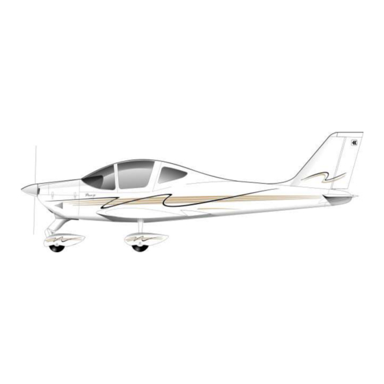
- Page 41 03-00 AIRPLANE GENERAL DESCRIPTION The P2002-JF is a twin-seat, single-engine, low wing, metal structure monoplane with fixed tricycle landing gear and steerable nose gear. Figure 1: General Views Edition – Rev 0 Page 1 03-00 AIRPLANE GENERAL DESCRIPTION...
- Page 42 Wing Each wing consists of a central light alloy torque box which carries all the wing bending, shear and torque loads; an aluminum leading edge is attached to the front spar while flap and aileron are hinged to the rear spar. Flap and aileron, respectively located inboard and outboard of wing and made up of light alloy, are constructed with a central spar to which front and rear ribs are jointed.
- Page 43 Fuselage The fuselage comprises the cabin and the baggage compartment. It is composed by a light-alloy semi-monocoque structure wrapped-around by stressed stretched panels. Nose cone is made of composite material. Tail fairing is made of composite material. Cabin and baggage compartment floor is a warping of beams and keelsons supporting the seats guides, baggage and other components.
- Page 44 Empennages The vertical tail is entirely metallic: vertical fin is made up of a twin spar with aluminum alloy stressed skin. Rudder, providing directional control of the airplane, is made up of aluminium alloy. The rudder is connected to the vertical tail at two hinges. REAR SPAR RUDDER TIP FRONT SPAR...
- Page 45 The horizontal empennage is an all-moving type (stabilator); its structure consists of a twin spar to which six ribs are joined and it is covered by stressed aluminum alloy skin. The trim tab completes the assy. Figure 5: Stabilator structure Edition –...
- Page 46 Flight Controls The flight control system controls the airplane in three axes. Ailerons, rudder and stabilator are manually operated by a conventional control stick and rudder pedals, pulleys, cables, bellcranks and rods. Complete dual controls are provided for pilot and co-pilot. Longitudinal control acts through a system of push-pull rods connected to the control stick and moving the stabilator whose anti-servo tab works also as trim tab electrically operated.
- Page 47 Rudder is operated through a cable system. The rudder has a trim tab adjustable on the ground: allows aircraft directional trimming. Figure 7: Flight control system (Flaps) Edition – Rev 0 Page 7 03-00 AIRPLANE GENERAL DESCRIPTION...
- Page 48 Engine and Propeller Aircraft is powered by Rotax 912 S2 engine featuring 4 cylinders horizontally opposed with 1352 c.c. of overall displacement, liquid cooled cylinder heads, ram-air cooled cylinders, carburetor, integrated reduction gear box with torsional shock absorber and overload clutch. Propeller is made by Hoffmann Propeller.
- Page 49 Landing Gear Main landing gear is provided by leaf springs fixed by plates to the central main bean of aircraft fuselage. Nose landing gear has a non-retractile leg with a rubber disc-dumper. Figure 9: Nose landing gear Figure 10: Main landing gear Edition –...
- Page 50 Brake System Wheels feature hydraulically actuated disc brakes (see Figure 10) controlled by a lever (1) located on cabin tunnel between seats. Main gear wheels mount Air Trac type 5.00-5 tires inflated at 23 psi (1.6 bar). Hydraulic circuit shut-off valve (2) is positioned between seats. With circuit shut off, pulling emergency brake lever activates parking brake function.
- Page 51 The differential brake circuit as shown in the Figure 11 (Optional). Control lever (1) activates pump (3) that features built-in brake fluid reservoir (4); check valve (5) secure brake function when activated , unintentionally, parking brake. Figure 11: Hydraulic differential brake circuit (Optional) Edition –...
- Page 52 Fuel System The fuel system consists of with two aluminum fuel tanks integrated within each wing leading edge. In normal conditions, the engine-driven gear pump sucks fuel from the selected tank. Fuel valve is located on cabin central tunnel: it allows to switch LH and RH tank. An electric fuel pump supplies the engine in case of engine-driven pump failure.
- Page 53 Electrical System The Electrical System is characterized by a nominal voltage of 14 VDC. The power supply is assured by a battery and by one internal engine-driven generator. The battery, of lead-acid type featuring 12 V 18-Ah in 1h, acts as a pad and supplies the energy for engine starting.
- Page 54 Pitot and Static System The aircraft has a single pitot tube, located on the bottom side of LH wing. Figure 14: Pitot system scheme Edition – Rev 0 Page 14 03-00 AIRPLANE GENERAL DESCRIPTION...
- Page 55 Ventilation, Cabin Heat and Windshield Defrost If required, using a handle, pilot allows ram-air to enter in the cabin via the two outlet ports respectively located on the left and right side of the instruments panel. The cabin heating system utilizes hot air coming from engine heat exchanger: here cold ram-air is warmed by engine exhaust gases and then it is routed to the heating system hoses.
- Page 56 General Features Following tables provide general information about airplane and its systems. The dimensions reported hereinafter are for reference only and are not for inspection purposes. Wing Wing span 8.6 m Wing surface 11.5 m Wing loading 50 kg/m Aspect ratio Taper ratio Dihedral 5°...
- Page 57 Engine Manufacturer Bombardier-Rotax GmbH Model 912 S2 Type 4 cylinder horizontally-opposed twins with overall displacement of 1352 c.c., mixed cooling, (water-cooled heads and air-cooled cylinders), twin carburetors, integrated reduction gear with torque damper. Maximum rating 73.5 kW (98.6 hp) @ 5800 rpm - max. 5 min. 69.0 kW (92.5 hp) @ 5500 rpm - continuous Propeller Manufacturer...
- Page 58 INTENTIONALLY LEFT BLANK Edition – Rev 0 Page 18 03-00 AIRPLANE GENERAL DESCRIPTION...
- Page 59 Chapter Airworthiness limitations The Airworthiness Limitations Section is EASA approved and variations must also be approved. Edition – Rev 0...
- Page 60 INTENTIONALLY LEFT BLANK Edition – Rev 0...
- Page 61 CHAPTER 04 LOEP Section Page Edition / Revision Edition, Rev 0 04-LOEP Edition, Rev 0 04-TOC Edition, Rev 0 Edition, Rev 0 04-00 Edition, Rev 0 Edition, Rev 0 Page 1 Edition – Rev 0 04 LOEP...
- Page 62 INTENTIONALLY LEFT BLANK Page 2 Edition – Rev 0 04 LOEP...
- Page 63 CHAPTER 04 TABLE OF CONTENTS 04-00 AIRWORTHINESS LIMITATIONS ..................1 Introduction ........................... 1 Airworthiness Limitation Table ....................2 Edition – Rev 0 Page 1 04 TOC...
- Page 64 04-00 AIRWORTHINESS LIMITATIONS Introduction The Airworthiness Limitations are approved and set mandatory by the European Aviation Safety Agency (EASA) under Appendix G, Section G 23.4 of EASA CS23. This section sets forth mandatory replacement time, life limited structural items and the inspection intervals and procedures necessary to maintain the airworthiness conditions required for Type Certification as a result of the certification process.
- Page 65 Airworthiness Limitation Table ITEM REQUIREMENT LIMIT Component Part number MAC6A Electri trim actuator 1000 hrs or 10 life limit stabilator T2-10A 1200 hrs or 10 Shock absorber pads 92-8-200-1 Life limit 22-9-120-1 22-9-122-1 Fuel hose flexible line 22-9-124-000 22-9-130-000* 22-9-132-000 Life limit 2 yrs 22-9-155-1 (2pz)
- Page 66 INTENTIONALLY LEFT BLANK Edition – Rev 0 Page 3 04-00 AIRWORTHINESS LIMITATIONS...
- Page 67 Chapter Time Limits and Maintenance schedule Edition - Rev 0...
- Page 68 INTENTIONALLY LEFT BLANK Edition - Rev 0...
- Page 69 CHAPTER 05 LOEP Section Page Edition / Revision Edition, Rev 0 05-LOEP Edition, Rev 0 Edition, Rev 0 Edition, Rev 0 05-TOC Edition, Rev 0 Edition, Rev 0 05-00 Edition, Rev 0 Edition, Rev 0 05-10 Edition, Rev 0 Edition, Rev 0 Edition, Rev 0 Edition, Rev 0 Edition, Rev 0...
- Page 70 Section Page Edition / Revision Edition, Rev 0 Edition, Rev 0 Edition, Rev 0 Edition, Rev 0 Edition, Rev 0 Edition, Rev 0 Edition, Rev 0 Edition, Rev 0 Edition, Rev 0 05-30 Edition, Rev 0 Edition, Rev 0 Edition, Rev 0 Edition, Rev 0 Edition, Rev 0 Edition, Rev 0...
- Page 71 Section Page Edition / Revision Edition, Rev 0 Edition, Rev 0 Edition, Rev 0 05-60 Edition, Rev 0 Edition, Rev 0 Edition, Rev 0 Edition - Rev 0 Page 3 05-00 LOEP...
- Page 72 INTENTIONALLY LEFT BLANK Edition - Rev 0 Page 4 05-00 LOEP...
- Page 73 CHAPTER 05 TABLE OF CONTENTS 05-00 GENERAL .......................... 1 05-10 COMPONENT TIME LIMITS ....................1 Time limits table ........................1 05-20 INSPECTION PROGRAM ....................1 Engine inspections ........................ 4 Propeller inspections ......................4 Vendor equipment inspections .................... 4 05-30 LUBRICATION ........................1 05-40 CORROSION PREVENTION ....................
- Page 74 INTENTIONALLY LEFT BLANK Edition - Rev 0 Page 2 05-00...
- Page 75 The flight time recorded in the airplane log book is the time that is applicable for the time limits. For vendor equipment installed in Tecnam aircraft, make sure to consult applicable maintenance instructions, in terms of time lim- its addressed on vendor publications. Inobservance of this rec- WARNING ommendation may affect the aircraft airworthiness.
- Page 76 INTENTIONALLY LEFT BLANK Edition - Rev 0 Page 2 05-00 GENERAL...
- Page 77 05-10 COMPONENT TIME LIMITS Time limits table This section lists the Time Between Overhauls (TBO) of components that are rec- ommended to be replaced or overhauled within the specified time limits. ITEM REQUIRE- LIMIT MENT Component Part number Kemet-ALS30A223DB025 1000 hrs/4 years Capacitor Life limit Or BHC 105-408...
- Page 78 INTENTIONALLY LEFT BLANK Edition - Rev 0 Page 2 05-10 COMPONENT TIME LIMITS...
- Page 79 05-20 INSPECTION PROGRAM The following table shows the maintenance tasks performed at defined intervals to retain an item in a serviceable condition by systematic inspection, detection, re- placement of wear out items, adjustment, calibration, cleaning, etc. as applicable. The inspections are grouped as follows: ...
- Page 80 FILTERS and FLUID for cleanliness, contamination and/or replacement if re- quired. Make sure that all Airworthiness Directives and Service Bulletins are implement- ed as required. Tecnam can change the time between checks publishing the change as a revision of this Maintenance Manual. Edition - Rev 0...
- Page 81 INTENTIONALLY LEFT BLANK Edition - Rev 0 Page 3 05-20 INSPECTION PROGRAM...
- Page 82 1. Engine inspections Refer to Rotax Engine Maintenance Manual P/N 899191 -last issue - for engine inspections and maintenance with related schedule. Consult also applicable ser- vice bulletins and instruction books regarding the repair and overhaul, inspection and installation of engines. 2.
- Page 83 4. Scheduled maintenance FREQUENCY Item Maintenance task Lubrication Perform lubrication tasks: refer to points Chapter 05-30 for Lubrication Charts and related frequencies. Inspection caps Before installing the caps removed for maintenance purposes, inspect for absence of loose tools, especially in correspondence of the flight controls.
- Page 84 FREQUENCY Item Maintenance task Heating and Check the air scoops for condition ventilation and free movement. Heating and Inspect cabin heat and defrost con- ventilation trols for operation and condition. Check operation, restricted movement, interference or unusual play. Check defrost valve for opera- tion.
- Page 85 FREQUENCY Item Maintenance task Electrical system Remove all inspection caps and in- spect all electrical wires, connectors and attaching parts for security, rout- ing, chafing, deterioration, wear and correct installation. Check bus bars for general condition, Electrical system cleanliness, and security of all at- tachments and terminals.
- Page 86 FREQUENCY Item Maintenance task Flight controls Inspect stabilator trim: check for full travel and correct operation. Check related indicator for operation. Fuel System Check fuel pump electrical connec- tions. Check fuel line connections for leakage. Control fireproof socks. Fuel System Clean electrical fuel pump filter.
- Page 87 FREQUENCY Item Maintenance task Indicating system Inspect all instruments markings for their readability and wear. Landing gear Inspect nose and main gear attach- ments, bolts and bushings for condi- tion and security. Check especially for cracks, corrosion and damaged surface protection. Inspect for loose- ness, condition and security of mounting points.
- Page 88 FREQUENCY Item Maintenance task Landing gear Check for play in wheel bearings. Examine wheels: look especially for cracks. Visually inspect the brakes and examine linings for excessive wear (if required replace linings) and disks for distortion and excessive wear. Landing gear Inspect the brakes lines and check re- taining clamps.
- Page 89 FREQUENCY Item Maintenance task Lights Check instruments lights, cockpit cabin and switches lights and related dimmers devices operate correctly. Lights Check emergency light(courtesy light for operation (if installed). Navigation Inspect Navigation equipment for general condition, operation and se- curity of installation. Navigation Inspect electronic installations for condition and security: check anten-...
- Page 90 FREQUENCY Item Maintenance task Inspect cabin truss for deformations Fuselage and corrosion Check seat rails and stops and safety Fuselage belt attachments Check internal condition of tailcone Fuselage structure Stabilator and Inspect rudder for surface damage or Rudder irregularities (skin cracks, distortion, dents, corrosion), structural defects (loose or missing rivets), hinges and bearings damage and excessive wear,...
- Page 91 FREQUENCY Item Maintenance task Windows Inspect windows for condition and security. Wings Inspect wing surfaces and tips for damage and loose rivets. Check wing lower skin drain holes free of obstruc- tions. Visually inspect the internal structure of the wing through wings inspections caps.
- Page 92 FREQUENCY Item Maintenance task Wings Inspect flap actuation mechanism and electrical connections. Check for condition, full travel and correct op- eration. Check related indicator for operation. Wings Disconnect wings from fuselage, raise them enough to allow for check- ing condition of attachments and for likely play Wings Inspect control surfaces electrical...
- Page 93 FREQUENCY Item Maintenance task Power Plant Check on the air box the carburetor heating control leverage for condition and operation. Power Plant Check for free movement of throttle, choke and carburetor heat levers. Check bowden cables full travel and correct operation. Check for restricted movement, interference or unusual play.
- Page 94 FREQUENCY Item Maintenance task Exhaust Disassembly the Exhaust system and check all the system for damage or cracks. Exhaust Muffle mounting springs: check for integrity. Exhaust Remove and inspect heat exchanger 200 hr. Oil system Check oil circuit: there should be no indication of leakages Oil system Disassembly, check and rinse the oil...
- Page 95 INTENTIONALLY LEFT BLANK Edition - Rev 0 Page 17 05-20 INSPECTION PROGRAM...
- Page 96 INTENTIONALLY LEFT BLANK Edition - Rev 0 Page 18 05-20 INSPECTION PROGRAM...
- Page 97 05-30 LUBRICATION Foreword Proper lubrication procedures allow for a/c service life extension and for reducing the frequency of extensive and expensive repairs. In addition, periodic application of recommended lubricants, as detailed in the following paragraphs, and observance of parts cleanliness will insure the maximum efficiency of all moving parts.
- Page 98 Approved lubricants Approved lubricants are reported in the following table: SPECIFICATION LUBRICANT MIL-G-3278 Grease, generic lubrication (e.g. ESSO Beacon 325) MIL-G-25013E Grease, bearings lubrication (e.g. AEROSHELL Grease No. 15) Universal Airframe Grease AEROSHELL Grease No. 33 Grease, bearings lubrication AEROSHELL Grease No. 5 MIL-PRF-23827C Multi purpose aerosol grease (e.g.
- Page 99 Lubrication charts and schedule The lubrication charts consist of individual illustrations for the various aircraft systems; for each component to be lubricated, identified by a number, it is reported the frequency of application. The same number is reported on the applicable component illustra- tion/schematic which shows in detail the lubrication points.
- Page 100 Item no. Lubrication points Frequency Stabilator rod end 100 Hrs Hinges 100 Hrs Aileron bushing 100 Hrs Aileron rod end 100 Hrs Aileron rod loop 100 Hrs Flap rod end 100 Hrs Flap rod attachment RH 100 Hrs Flap rod attachment LH 100 Hrs Flap actuator attachments 100 Hrs...
- Page 101 Figure 1. - Inspection points Edition - Rev 0 Page 5 05-30 LUBRICATION...
- Page 102 Figure 2. - Inspection points (details) Edition - Rev 0 Page 6 05-30 LUBRICATION...
- Page 103 Figure 3. - Rudder upper bushing Figure 4. - Rudder lower bushing and teflon road-stop Edition - Rev 0 Page 7 05-30 LUBRICATION...
- Page 104 Figure 5. - Stabilator rod-end Figure 6. - Stabilator supports Edition - Rev 0 Page 8 05-30 LUBRICATION...
- Page 105 Figure 7. - Stabilator supports Edition - Rev 0 Page 9 05-30 LUBRICATION...
- Page 106 Figure 8. - Aircraft moving surfaces hinges Figure 9. - Flaps lower bushing Edition - Rev 0 Page 10 05-30 LUBRICATION...
- Page 107 Figure 10. - Stabilator rod loops Figure 11. - Stabilator rod end Edition - Rev 0 Page 11 05-30 LUBRICATION...
- Page 108 Figure 12. – Aileron rod ends and rotation bushing Figure 13. - Aileron rod loop Edition - Rev 0 Page 12 05-30 LUBRICATION...
- Page 109 Figure 14. - Flap rod end Figure 15. - Flap rod attachments (RH) Edition - Rev 0 Page 13 05-30 LUBRICATION...
- Page 110 Figure 16. - Flaps rod attachment (LH) and Flaps actuator attachments Edition - Rev 0 Page 14 05-30 LUBRICATION...
- Page 111 Figure 17. - Pedals and rudder cables attachments Figure 18. - Steering attachments Edition - Rev 0 Page 15 05-30 LUBRICATION...
- Page 112 Figure 19. - Brake attachments (If Applicable) Figure 20. - Control column Edition - Rev 0 Page 16 05-30 LUBRICATION...
- Page 113 Figure 21. - Shock absorber attachments Figure 22. - NLG Attachment and steering attachments Edition - Rev 0 Page 17 05-30 LUBRICATION...
- Page 114 Figure 23. - Pedals attachments (If Applicable) Figure 24. - Brakes pump attachments (If Applicable) Edition - Rev 0 Page 18 05-30 LUBRICATION...
- Page 115 Figure 25. – Connection pedal-rudder Figure 26. – Steering control road Edition - Rev 0 Page 19 05-30 LUBRICATION...
- Page 116 Figure 27. – Parking brake lever (If Applicable) Figure 28. – Main gear wing bearings Edition - Rev 0 Page 20 05-30 LUBRICATION...
- Page 117 Figure 29. – Nose gear wing bearings (42) Edition - Rev 0 Page 21 05-30 LUBRICATION...
- Page 118 After cleaning surface corrosion, parts must be treated with an anti-corrosion product. Tecnam suggests for steel and aluminum parts as anticorrosion product, ACF-50 or products with similar technical features, which stops the existing corrosion and remain effective for 24 months.
- Page 119 The surfaces that need particular care are the following: Area Component Inspection compartments, wing attach- Fuselage ments, stabilator attachments MLG compartment, NLG compartment, Landing gear springs, gear attachment, metric bolts, nuts and pins Wing section and hinges LH and RH wing attachment plates Vertical and horizontal stabilizers an hing- All metric bearings and terminals Engine compartment...
- Page 120 05-50 SPECIAL SCHEDULED MAINTENANCE In addition to those listed on Section 05.20, following inspections are required at speci- fied time intervals as consequence of the particular environment which the aircraft is operated in. Unless otherwise indicated, these inspections are to be repeated at each oc- currence of the specified interval.
- Page 121 Operation in High Salt or High Humidity Environments In case of aircraft operating in high salt of high humidity environment (e.g. air- craft operating over salt water), following scheduled maintenance tasks shall be applied: INSPECTION ITEM INSPECTION INTERVAL Remove floor panels and exterior ac- Fuselage, Empennage, Wings cess plates;...
- Page 122 INSPECTION ITEM INSPECTION INTERVAL Inspect top coat finish for breaks, peel- ing, lifting of surface, or other dam- Fuel tanks age. Inspect aircraft structure for top 100 hours or 1 year WOF coat finish damage from pitting or in- ter-granular corrosion. Inspect hose assemblies for chafing, weather-checking, hardening, discol- oration, evidence of fungus, torn...
- Page 123 5. Wipe off excess mixture. When applying the mixture take care that as little as pos- sible is deposited on exhaust pipes or collector rings to avoid a fire hazard when the engine is started. Keep the ignition wires, tires and other rubber parts free of the mixture.
- Page 124 Operation in Extreme Cold Environment INSPECTION ITEM INSPECTION INTERVAL Hydraulic, Pneumatic and Check all fittings and attachments First 100 hours, then as Environmental. for security and leaks. required Operation on Soft or Unusual Terrain INSPECTION ITEM INSPECTION INTERVAL Inspect for cracks, attachment, Landing Gear damages, cleanliness and lubrica- 100 hours...
- Page 125 INTENTIONALLY LEFT BLANK Edition - Rev 0 Page 6 05-50 SPECIAL SCHEDULED MAINTENANCE...
- Page 126 05-60 UNSCHEDULED MAINTENANCE The following inspections are required in response to specific anomalies encountered during aircraft operation. Note that the items listed herein are guidelines based on past operating experience. Each operator should closely monitor his own unique operating conditions/environment and react accordingly to keep his aircraft airworthy. NOTE: for engine unscheduled maintenance, make reference to applicable Rotax Engine Maintenance Manual –...
- Page 127 - Make a preliminary inspection checking alignment and out-of-track condition of engine, wings, tail, landing gear and doors. - Follow Tecnam P2002 JF and Rotax Maintenance Manuals for procedures. If there any question regarding repairs or procedures, contact your Tecnam dis- tributor’s service advisor (DSA).
- Page 128 INSPECTION ITEM INSPECTION INTERVAL Landing gear attach Buckling, cracks, overstress, wing Each occurrence, before points. (Not required for skin buckling and side brace for further flight. severe turbulence.) damage and condition. Inspect land- ing gear attachment bolts (magnetic particle method). Wings Wing attachment bolts for slippage, Each occurrence, before...
- Page 129 Particular attention to silt, corrosion and contaminants. - Follow Tecnam and Rotax Maintenance Manual procedures. If there are any questions regarding repairs or procedures, contact Tecnam. - Determine the water level on the aircraft. Determine which operating and/or electrical components have been exposed to the water.
- Page 130 INSPECTION ITEM INSPECTION INTERVAL External and internal sur- As soon as possible after the aircraft is If immersed, each occur- faces recovered from water immersion, rence, before further thoroughly wash all internal and ex- flight. ternal areas of the aircraft using a wa- ter/detergent solution as follows.
- Page 131 INSPECTION ITEM INSPECTION INTERVAL Airframe The salvable components of the fuse- If immersed, each occur- lage, wings, empennage and movable rence, before further surfaces should be processed as fol- flight. lows. Clean the aircraft interior and exterior using steam under pressure with steam cleaning compound.
- Page 132 INSPECTION ITEM INSPECTION INTERVAL Flight control system Clean and inspect all cables, pulleys, If immersed, each occur- and bearings, for evidence of corro- rence, before further sion. Replace corroded cables. Do not flight. apply preservation to cables. Trim control system Clean and inspect all trim system ca- If immersed, each occur- bles, pulleys, bearings jack screws,...
- Page 133 INSPECTION ITEM INSPECTION INTERVAL Fuel system Clean fuel tanks and filters. Clean all If immersed, each occur- associated lines and pumps. Clean and rence, before further inspect all fuel tank vents cap and vent flight. lines. Instruments Clean and inspect instruments. Bench If immersed, each occur- test per appropriate maintenance man- rence,...
- Page 134 INTENTIONALLY LEFT BLANK Edition - Rev 0 Page 9 05-60 UNSCHEDULED MAINTENACE...
- Page 135 Chapter Dimensions and inspection caps Edition – Rev 0...
- Page 136 INTENTIONALLY LEFT BLANK Edition – Rev 0...
- Page 137 CHAPTER 06 LOEP Section Page Edition / Revision Edition, Rev 0 06-LOEP Edition, Rev 0 06-TOC Edition, Rev 0 Edition, Rev 0 Edition, Rev 0 06-00 Edition, Rev 0 Edition, Rev 0 Edition, Rev 0 Edition, Rev 0 06-10 Edition, Rev 0 Edition, Rev 0 Edition, Rev 0 Edition –...
- Page 138 INTENTIONALLY LEFT BLANK Edition – Rev 0 Page 2 O6 LOEP...
- Page 139 CHAPTER 06 TABLE OF CONTENTS 06-00 DIMENSIONS AND AREAS ....................1 General Dimensions ...................... 1 Control Surfaces Travel Limits ..................3 06-10 INSPECTION CAPS ......................1 Edition – Rev 0 Page 1 O6 TOC...
- Page 140 06-00 DIMENSIONS AND AREAS This chapter gives the airplane major dimensions and areas. The International System is used; in any case Chapter 02 provides unit conversion charts. General Dimensions Following figure addresses the airplane general dimensions. Edition – Rev 0 Page 1 O6-00 DIMENSIONS AND AREAS...
- Page 141 Wing Wing span 8,6 m 28,2 ft Wing surface 11,5 m 92,6 ft Wing loading 50 kg/m 10,2 lb/ft Aspect ratio Taper ratio Dihedral 5° Fuselage Length overall 6,61 m 21,7 ft Width overall 1,11 m 3,6 ft Height overall 2,43 m 10,0 ft Empennage...
- Page 142 Cabin dimensions Figure 1: Cabin dimensions Control Surfaces Travel Limits Up 20° 2°; down 15° 2° Ailerons Up 3° 1°; down 15° 1° Stabilator Up 2° 1°; down 9° 1° Trim LH 30° 2°; RH 30° 2° Rudder Up 0°...
- Page 143 INTENTIONALLY LEFT BLANK Edition – Rev 0 Page 4 O6-00 DIMENSIONS AND AREAS...
- Page 144 06-10 INSPECTION CAPS An index number has been assigned to each opening for identifying the access. All access plates and panels are secured by either metal fasteners or screws and are identified as follows: (1) The suffix is the zone location, namely C: cabin CF: cabin floor E: engine nacelle...
- Page 145 Figure 2: Inspection caps Edition – Rev 0 Page 2 O6-10 INSPECTION CAPS...
- Page 146 INSPECTION CAPS AND REMOVABLE PARTS ACCESS TO Q.TY 2 – LH and RH Aileron differential bellcranck 2 – LH and RH Wing tank outlet, main spar and torque box 2 – LH and RH Flap control rod and wing rear fitting point 2 –...
- Page 147 INTENTIONALLY LEFT BLANK Edition – Rev 0 Page 4 O6-10 INSPECTION CAPS...
- Page 148 INTENTIONALLY LEFT BLANK Edition – Rev 0 Page 5 O6-10 INSPECTION CAPS...
- Page 149 Chapter Jacking Edition – Rev 0...
- Page 150 INTENTIONALLY LEFT BLANK Edition – Rev 0...
- Page 151 CHAPTER 07 LOEP Section Page Edition / Revision Edition, Rev 0 07 LOEP Edition, Rev 0 Edition, Rev 0 07 TOC Edition, Rev 0 Edition, Rev 0 Edition, Rev 0 07-00 Edition, Rev 0 Edition, Rev 0 Edition – Rev 0 Page 1 O7 LOEP...
- Page 152 INTENTIONALLY LEFT BLANK Edition – Rev 0 Page 2 O7 LOEP...
- Page 153 CHAPTER 07 TABLE OF CONTENTS 07-00 JACKING – MAINTENANCE PRACTICES ................200 General ........................ 200 Jacking the aircraft ....................200 Removing airplane from jacks ................202 Edition – Rev 0 Page 1 O7 TOC...
- Page 154 INTENTIONALLY LEFT BLANK Edition – Rev 0 Page 2 O7 TOC...
-
Page 155: Jacking The Aircraft
07-00 JACKING – MAINTENANCE PRACTICES General For the aircraft jacking , two lifting points are provided under the two outer keelsons, on both sides od fuselage. The lifting point consists of a small aluminium cylinder fastened to the outer keelsons. Below of it could be placed either a hydraulic jack or a lifting rod. The lifting ... - Page 156 Procedure Tow the aircraft on a level surface Engage parking brake, make sure Master Switch is OFF Place the nose trestle at the first fuselage in order to keep the nose wheel off the ground for at least 7 cm about (3 in.) Place jacks, with related adapters, at MLG jacking points locations (refer to Figure 2) In order to prevent unintended a/c unbalancing during jacks operation, it is advisable a third person is next to the a/c tail.
- Page 157 Removing airplane from jacks Make sure parking brake is engaged Remove tail trestle (installed during the jacking procedure) In order to prevent unintended a/c unbalancing during jacks operation, it is advisable a third person is next to the a/c tail. Lower MLG jacks until airplane rests on MLG and jacks can be removed Remove jacks and trestle Edition –...
- Page 158 INTENTIONALLY LEFT BLANK Edition – Rev 0 Page 203 07-00 JACKING – MAINTENANCE PRACTICES...
- Page 159 Chapter Leveling and Weighing Edition – Rev 0...
- Page 160 INTENTIONALLY LEFT BLANK Edition – Rev 0...
- Page 161 CHAPTER 08 LOEP Section Page Edition / Revision Edition, Rev 0 08 LOEP Edition, Rev 0 Edition, Rev 0 08 TOC Edition, Rev 0 Edition, Rev 0 08-10 Edition, Rev 0 Edition, Rev 0 Edition, Rev 0 Edition, Rev 0 08-20 Edition, Rev 0 Edition, Rev 0...
- Page 162 INTENTIONALLY LEFT BLANK Edition – Rev 0 Page 2 O8 LOEP...
- Page 163 CHAPTER 08 TABLE OF CONTENTS 08-10 LEVELING ........................200 General ..........................200 Longitudinal leveling ......................201 Transversal Levelling ......................202 08-20 WEIGHING ........................200 General ..........................200 Procedure .......................... 201 Edition – Rev 0 Page 1 O8 TOC...
- Page 164 INTENTIONALLY LEFT BLANK Edition – Rev 0 Page 2 O8 TOC...
- Page 165 08-10 LEVELING General The aircraft is provided with means for longitudinal and lateral leveling. The aircraft may be leveled while on the jacks (see Chapter 07 for jacking procedures), during the weighing procedure while the wheels are on the scales, or while the wheels are on the ground during other operations.
- Page 166 Longitudinal leveling Procedure To check the longitudinal leveling act as follows: Slide off one of the two seat to get the access to the two seat track’s supporting trusses. Place longitudinally a spirit or water level over the two supporting trusses using, if necessary, a straight piece of wood as indicated into figure 1.
- Page 167 Transversal Levelling With one seat removed place a level along the forward seat track’s supporting truss. Level the aircraft by deflating the main gear tyres. Edition – Rev 0 Page 202 O8-10 LEVELING...
- Page 168 08-20 WEIGHING General Before applying weighing procedure: - make sure fuel tanks contain unusable fuel only; - remove all loose items which are not included in the basic empty weight figures; - make sure baggage compartment is empty. All weighing operations must be conducted in a closed hangar and taking care that no air currents pass over the airplane during weighing, otherwise inaccurate readings could result.
- Page 169 Procedure The aircraft must be weighed according to the following procedure: 1. Carry out weighing procedure inside hangar 2. Remove any unnecessary objects inadvertently left on board aircraft 3. Make sure of the on-board presence of the Flight Manual or other instruments manuals (e.g.
- Page 170 Model: P2002 JF S/N:________ Weighing no. _________ Date:_________ Datum: leading edge vertical CMA 1370 15 mm inboard from rib n°7 1337 from the propeller's flange (without sapacer) Reference line W2 * A - W1 * B W1 + W2 D% =...
- Page 171 INTENTIONALLY LEFT BLANK Edition – Rev 0 Page 203 O8-20 WEIGHING and BALANCE...
- Page 172 INTENTIONALLY LEFT BLANK Edition – Rev 0 Page 204 O8-20 WEIGHING and BALANCE...
- Page 173 Chapter Towing and Taxiing Edition – Rev 0...
- Page 174 INTENTIONALLY LEFT BLANK Edition – Rev 0...
- Page 175 CHAPTER 09 LOEP Section Page Edition / Revision Edition, Rev 0 09 LOEP Edition, Rev 0 Edition, Rev 0 09 TOC Edition, Rev 0 Edition, Rev 0 09-10 Edition, Rev 0 Edition, Rev 0 09-20 Edition, Rev 0 Edition – Rev 0 Page 1 O9 LOEP...
- Page 176 INTENTIONALLY LEFT BLANK Edition – Rev 0 Page 2 O9 LOEP...
- Page 177 CHAPTER 09 TABLE OF CONTENTS 09-10 TOWING ........................200 MAINTENANCE PRACTICES ................... 200 09-20 TAXIING ........................200 MAINTENANCE PRACTICES ................... 200 Edition – Rev 0 Page 1 09 TOC...
- Page 178 INTENTIONALLY LEFT BLANK Edition – Rev 0 Page 2 09 TOC...
- Page 179 09-10 TOWING AINTENANCE RACTICES General Move the aircraft on ground by pulling on the propeller blades close to hub. A tow bar can be attached to fittings. Aircraft can be steered using the rudder or, for sharp turns, by lowering the tail to raise nose wheel off the ground. In this case, owing to the favorable CG location, a gentle push on the tail cone just ahead of empennage surfaces is all that is needed.
- Page 180 INTENTIONALLY LEFT BLANK Edition – Rev 0 Page 201 09-10 TOWING – MAINTENANCE PRACTICES...
- Page 181 09-20 TAXIING AINTENANCE RACTICES General Before attempting to taxi the aircraft, ground personnel should be checked out by a qualified pilot or other responsible person. Engine starting and shutdown procedures should be covered as well. Taxiing requires two persons, one to maneuver the airplane and one to assist and act as an observer.
- Page 182 INTENTIONALLY LEFT BLANK Edition – Rev 0 Page 201 09-20 TAXIING – MAINTENANCE PRACTICES...
- Page 183 Chapter Parking, Mooring, Storage and Return to Service Edition – Rev 0...
- Page 184 INTENTIONALLY LEFT BLANK Edition – Rev 0...
- Page 185 CHAPTER 10 LOEP Section Page Edition/Revision Edition – Rev 0 LOEP Edition – Rev 0 Edition – Rev 0 Edition – Rev 0 10-10 Edition – Rev 0 10-20 Edition – Rev 0 Edition – Rev 0 10-30 Edition – Rev 0 Edition –...
- Page 186 INTENTIONALLY LEFT BLANK Edition – Rev 0 Page 2 10 LOEP...
- Page 187 CHAPTER 10 TABLE OF CONTENTS 10-10 PARKING ..................200 General ......................200 Procedure....................... 200 10-20 MOORING ..................200 Procedure....................... 200 10-30 STORAGE AND RETURN TO SERVICE ........... 200 General ......................200 Storage ......................200 Restoration from storage ................201 Edition – Rev 0 Page 1 10 TOC...
- Page 188 INTENTIONALLY LEFT BLANK Edition – Rev 0 Page 2 10 TOC...
- Page 189 10-10 PARKING General Under normal weather conditions, the airplane may be parked and headed in a direction that will facilitate servicing without regard to prevailing winds. Ensure that it is sufficiently protected against adverse weather conditions and presents no danger to other aircraft. Procedure 1.
- Page 190 10-20 MOORING General The aircraft is moored to insure its immovability, protection, and security under various weather conditions. Mooring is strongly recommended when the wind is more than 10knots and the a/c is completely refueled. CAUTION Procedure 1. Position airplane on levelled surface and headed into the prevailing wind, if practical.
- Page 191 Figure 1. – Mooring scheme Edition – Rev 0 Page 201 10-20 MOORING...
- Page 192 10-30 STORAGE AND RETURN TO SERVICE General If a long-term parking (more than 30 days) is required, the storage procedure allows protection of the airplane from deterioration while it is not in use. The primary objectives of these measures are to prevent corrosion and damage from exposure to the environmental elements.
- Page 193 Restoration from storage Procedure 1. Install the battery (see Chapter 12, battery installation procedure). 2. Check the wheels pressure. 3. Check oil and cooling system. 4. Reactivate ELT. 5. Remove chocks from wheels. 6. Engine: refer to Rotax Operator’s Manual P/N 899372 - Engine Back to Operation Instructions.
- Page 194 INTENTIONALLY LEFT BLANK Edition – Rev 0 Page 202 10-20 STORAGE AND RETURN TO SERVICE...
- Page 195 Chapter Markings and Placards Edition – Rev 0...
- Page 196 INTENTIONALLY LEFT BLANK Edition – Rev 0...
- Page 197 CHAPTER 11 LOEP Section Page Edition/Revision Edition – Rev 0 LOEP Edition – Rev 0 Edition – Rev 0 Edition – Rev 0 11-00 Edition – Rev 0 11-10 Edition – Rev 0 Edition – Rev 0 11-20 Edition – Rev 0 Edition –...
- Page 198 INTENTIONALLY LEFT BLANK Edition – Rev 0 Page 2 11 LOEP...
- Page 199 CHAPTER 11 TABLE OF CONTENTS 11-00 MARKINGS AND PLACARDS .............. 1 11-10 EXTERIOR COLOUR ............... 200 MAINTENANCE PRACTICES ................200 Paint Features ....................201 Ornament Removal ..................201 Ornament Installation ..................201 11-20 EXTERNAL PLACARDS ..............200 MAINTENANCE PRACTICES ................200 Placard Removal ....................
- Page 200 INTENTIONALLY LEFT BLANK Edition – Rev 0 Page 2 11 TOC...
- Page 201 11-00 MARKINGS AND PLACARDS Placards are used to identify the function, operation and operating limitations of systems and equipment. The model designation placard is located at the rear of the fuselage on the left side. The placard identifies the airplane manufacturer, airplane type and serial number, its identification marks and EASA Type Certificate number.
- Page 202 11-10 EXTERIOR COLOUR AINTENANCE RACTICES The exterior colour scheme is a customer option in accordance with Tecnam Design Organization Approval. Application of colours other than those approved by Tecnam may cause excessive temperatures and consequent degradation of structural properties of composite components A typical exterior colour scheme is reported below.
- Page 203 Paint Features The typical background colour is white: make reference to the table below showing the mentioned colour features. Colour RAL CODE Type Vendor Polyurethane Colorificio White 9016 enamel Sammarinese In the event of small areas requiring for painting, it is possible to use acrylic aerosol paint. Ornament Removal Tools Item...
- Page 204 Remove the protective covering from the adhesive side of the ornament and position the ornament pressing firmly to the surface. Edition – Rev 0 Page 202 11-20 EXTERIOR COLOR – MAINTENANCE PRACTICES...
- Page 205 11-20 EXTERNAL PLACARDS AINTENANCE RACTICES In this section are shown the external placards and their locations on the airplane. Placard Removal Tools Item Quantity Part Number / Notes Solvent Commercial type Procedure Detach the placard from the airplane using a hot air blower to soften the adhesive, taking care not to damage any adjacent component or paintwork.
- Page 206 Q.ty Item Description Fuel filler cap marking Canopy lock marking Wing no step zone marking Zero stabilator marking Tecnam Logo Tecnam Logo External power marking Battery marking MLG tires pressure marking NLG tire pressure marking P2002 logo Tail cone aircraft marking...
- Page 207 11-30 INTERNAL PLACARDS AINTENANCE PRACTICES In this section are shown the internal placards and their locations on the airplane. Some placards are self-adhesive, some are stiff riveted placards and some other ones are silk- screened (no replacement allowable for those installed on the instruments panel). Self-Adhesive Placard Removal Tools Item...
- Page 208 Stiff Riveted Placard Removal Tools Item Quantity Part Number / Notes Drill Commercial type Drill bit #3.25 mm Commercial type Procedure The rivets must be removed utilizing a #3.25 mm drill bit with an appropriate drill stop; carefully drill the rivet head with light pressure: heavy pressure can cause deformation of the substructure.
- Page 209 Figure 4. – Instrument panel (analogic system) Edition – Rev 0 Page 202 11-30 INTERNAL PLACARDS – MAINTENANCE PRACTICES...
- Page 210 Item Description Breaker panel Master generator ON/OFF Op. Limitations Aircraft logo No smoking Fuel Tank serigraph Annunciator panel serigraph Maneuvering speed Trim Switch First aid kit / Em. Hammer / Fire ext Throttle Choke Push Cabin Heat Carburetor Heat Trim Led Edition –...
- Page 211 Figure 5. – Internal placards Item Description Canopy lock Fuel selector command Parking brake Level point ind. Tie down/max press Emergency hammer Fire extinguisher Edition – Rev 0 Page 204 11-30 INTERNAL PLACARDS – MAINTENANCE PRACTICES...
- Page 212 INTENTIONALLY LEFT BLANK Edition – Rev 0 Page 205 11-30 INTERNAL PLACARDS – MAINTENANCE PRACTICES...
- Page 213 INTENTIONALLY LEFT BLANK Edition – Rev 0 Page 206 11-30 INTERNAL PLACARDS – MAINTENANCE PRACTICES...
- Page 214 INTENTIONALLY LEFT BLANK Edition – Rev 0 Page 207 11-30 INTERNAL PLACARDS – MAINTENANCE PRACTICES...
- Page 215 Chapter Servicing Edition – Rev 0...
- Page 216 INTENTIONALLY LEFT BLANK Edition – Rev 0...
- Page 217 CHAPTER 12 LOEP Section Page Edition/Revision Edition – Rev 0 LOEP Edition – Rev 0 Edition – Rev 0 Edition – Rev 0 Edition – Rev 0 12-00 Edition – Rev 0 Edition – Rev 0 12-10 Edition – Rev 0 Edition –...
- Page 218 INTENTIONALLY LEFT BLANK Edition – Rev 0 Page 2 12 TOC...
- Page 219 CHAPTER 12 TABLE OF CONTENTS 12-00 SERVICING ..................1 General ......................1 12-10 FUEL SYSTEM – SERVICING PRACTICES ........200 General ......................200 Refueling Procedure ..................202 Fuel Contamination Check Procedure............202 Fuel System Drainage Procedure ..............202 12-20 OIL SYSTEM - SERVICING PRACTICE ........... 200 General ......................
- Page 220 12-60 BATTERY – SERVICING PRACTICES ..........200 General ......................200 Removal Procedure ..................200 Installation Procedure ................... 200 12-70 WHEELS – SERVICING PRACTICES ..........200 General ......................200 12-80 BRAKE SYSTEM – SERVICING PRACTICES ........200 BRAKE TOE SYSTEM ..................200 General ......................
- Page 221 12-00 SERVICING General Servicing the aircraft includes the replenishment of fuel, oil, hydraulic fluid, tyre pressures, lubrication requirements and other items required to completely service the aircraft. The information in the following sections pertains to general maintenance procedures. Detailed information on the engines will be found in the engine Maintenance Manual. For inspection caps location, make reference to Chapter 06-10.
- Page 222 12-10 FUEL SYSTEM – SERVICING PRACTICES General Each fuel tank is filled through a single filler cap located on the wing upper skin. Each tank has a capacity of 50 Lt (100 Lt total fuel capacity), 0.5 Lt are unusable (1 Lt total fuel unusable).
- Page 223 Pictures below show the fuel filler cap and fuel sump drain valve location: Figure 1. - Drain Valve (RH Shown, LH Opp.) and Filler caps Edition – Rev 0 Page 201 12-10 FUEL SYSTEM – SERVICING PRACTICES...
- Page 224 Refueling Procedure Take care that no foreign objects are inadvertently introduced into the filling port. 1. Apply aircraft’s and refueling vehicle’s ground, through the engine muffle 2. Place a container under the fuel sump drain valve 3. Open the drain valve (refer to Figure 1) 4.
- Page 225 12-20 OIL SYSTEM - SERVICING PRACTICE General Following paragraphs shows the procedures for oil level checking, filling and change. : use only oil with API classification "SG" or higher. At the PPROVED OIL SPECIFICATION selection of suitable lubricant, refer to the additional information provided by Rotax Operators Manual P/N 899371 (Operating media Section) - last issue Make certain that fluids and fluid containers are protected from contamination of any kind..
- Page 226 Oil Level Checking and Filling Procedure 1. Open Engine cowling to access to oil tank (refer to Figure 2.) 2. Remove the filler cap; remove and clean the dipstick 3. Turn the propeller several times by hand in the direction of engine rotation to pump all the oil from the engine to the oil tank (the process is complete when air flows back to the oil tank, perceived by a gurgling) 4.
- Page 227 Figure 3. – Oil tank location Edition – Rev 0 Page 202 12-20 OIL SYSTEM – SERVICING PRACTICES...
- Page 228 Oil Change Procedure At the selection of suitable lubricants refer to the additional information provided by Rotax Operators Manual P/N 899371 - last issue 1. Remove upper and lower engine cowling 2. Run engine to warm oil before beginning oil change procedure 3.
- Page 229 1. Cup’s safety ring 2. Restraint clamps 3. Oil tank 4. Oil filling cup Figure 5. – Oil tank Oil Tank Cleaning In event of heavy oil contamination apply the following procedure: 1. Engage parking brake, master switch OFF, disconnect battery 2.
- Page 230 12-30 COOLANT SYSTEM – Servicing practices In order to equalize the pressure inside the engine cooling system, an expansion tank is provided in the highest point of the cooling system and it is fitted with a filler cap. The procedure for coolant replenishing is described below. : at the selection of suitable coolant, refer to the PPROVED COOLANT LIQUID SPECIFICATION information provided by Rotax Operators Manual P/N 899371 (Operating media Section) - last...
- Page 231 Figure 6. - Coolant expansion tank Figure 7. - Coolant overflow bottle Edition – Rev 0 Page 201 12-20 COOLANT SYSTEM – SERVICING PRACTICES...
- Page 232 12-40 SEATS – Handling and cleaning instructions General The P2002 has two seats, each seat is horizontally adjustable.. They are mounted on two parallel tracks, attached to the compartment floor structure, which allow the seat to move forward or rearward. Each seat consists of the following main components: (1) Primary Structure Assembly consisting of the sitting and backrest assemblies.
- Page 233 Seats Removal and Installation Procedure Procedure 1. Remove seats locking device (unscrew and remove, refer to Figure 9.) 2. Pull seat lever then slide seat all forward (refer to Figure 10.) 3. Pull Up seat and remove it from his location 4.
- Page 234 Seats Cleaning Instructions This section provides the information to perform seat cleaning procedure and related used products and materials. PERFORM CLEANING PROCEDURE IN A VENTILATED AREA. AVOID BREATHING SOLVENT VAPOURS AND PROLONGED SOLVENT CONTACT WITH SKIN. For additional information, refer to applicable CMM. Polycarbonate Components Cleaning Tools Item...
- Page 235 CAUTION: NEVER USE ABRASIVE OR HIGHLY ALKALINE CLEANER. POLYURETHANE LIFE WILL BE SERIOUSLY REDUCED AND CRACKING WILL OCCUR IF CLEANED WITH STRONG SOLVENTS. Leather Dress Cover Cleaning LEATHER DRESS COVER SHOULD BE CLEANED USING EXCLUSIVELY THE METHOD OF TREATMENT SWOWN IN THE TABLE BELOW.
- Page 236 12-50 AIRPLANE CLEANING INSTRUCTIONS General The aircraft should be washed with soapy water. Abrasive detergents or alkaline soaps used on painted or plastic surfaces could lead to scratches or cause corrosion of metal surface. Cover areas where cleaning solution could cause damage. How often the a/c should be cleaned depends on the environment in which it has been operating.
- Page 237 External Surfaces Cleaning Procedure To wash the aircraft the following procedure may be used: 1. Flush out dirt 2. Apply cleaning solution with sponge or soft bristle brush 3. To remove stubborn oil and grease use a kerosene moist cloth 4.
- Page 238 12-60 BATTERY – SERVICING PRACTICES General Battery is located in the fuselage and it is accessible through the cap F9. For battery electrolyte maintenance, use electrolyte (battery acid, dilute sulphuric acid). Check the battery cables connections, clean any liquid leakages. Small corrosion on the battery surface and on its container can be cleaned with bicarbonate and water.
- Page 239 Figure 11. – Anti vibration PAD Edition – Rev 0 Page 201 12-60 BATTERY SERVICING PRACTICES...
- Page 240 12-70 WHEELS – SERVICING PRACTICES General Nose and main tires must always be inflated to the correct pressure. Before the flight, check for damages, cuts, wear, etc. As safety general rule, when servicing aircraft tires, personnel should stand either in the front or rear of the wheel and avoid approaching from either side of the tire.
- Page 241 12-80 BRAKE SYSTEM – SERVICING PRACTICES LEVER TOE SYSTEM General Overall oil quantity in the brake system is 200ml (order of magnitude). Fluid is drawn from the reservoir by the brake cylinders to maintain the fluid volume required for maximum braking efficiency.
- Page 242 Figure 11. – Brake fluid reservoir TOE BRAKE SYSTEM (optional) General Overall oil quantity in the brake system is 400ml (order of magnitude). Fluid is drawn from the reservoir by the brake cylinders to maintain the fluid volume required for maximum braking efficiency.
- Page 243 The brake system operation with low oil level could affect the brakes’ performances and could cause permanent damage. Make certain that hydraulic fluids and fluid containers are protected from contamination of any kind. Dirt particles may cause hydraulic units to become inoperative, cause seal damage, etc.
- Page 244 INTENTIONALLY LEFT BLANK Edition – Rev 0 Page 203 12-80 BRAKE SYSTEM SERVICING PRACTICES...
- Page 245 INTENTIONALLY LEFT BLANK Edition – Rev 0 Page 204 12-80 BRAKE SYSTEM SERVICING PRACTICES...
- Page 246 INTENTIONALLY LEFT BLANK Edition – Rev 0 Page 205 12-80 BRAKE SYSTEM SERVICING PRACTICES...
- Page 247 Chapter Standard practices Airframe Edition – Rev 0...
- Page 248 INTENTIONALLY LEFT BLANK Edition – Rev 0...
- Page 249 CHAPTER 20 LOEP Section Page Edition/Revision Edition – Rev 0 20- LOEP Edition – Rev 0 Edition – Rev 0 20-TOC Edition – Rev 0 Edition – Rev 0 20-10 Edition – Rev 0 Edition – Rev 0 20-20 Edition – Rev 0 Edition –...
- Page 250 INTENTIONALLY LEFT BLANK Edition – Rev 0 Page 2 20 LOEP...
- Page 251 CHAPTER 20 TABLE OF CONTENTS 20-10 TORQUE DATA................201 MAINTENANCE PRACTICES ................201 General ......................201 Torque Values ....................202 20-20 CABLES TENSION ................200 MAINTENANCE PRACTICES ................200 20-30 CONTROL CABLES ................. 200 MAINTENANCE PRACTICES ................200 Inspection Technique ..................200 Cable damage ....................
- Page 252 20-10 TORQUE DATA AINTENANCE RACTICES General This paragraph gives the standard practices for torque loading nut and bolt combinations. The importance of correct torque application cannot be overemphasized. Undertorque can result in unnecessary wear of nuts and bolts, as well as the parts they secure. Overtorque can cause failure of a bolt or nut from overstressing the threaded areas.
- Page 253 Figure 1. - Torque wrench with various adapters Edition – Rev 0 Page 201 20-10 TORQUE DATA – MAINTENANCE PRACTICES...
- Page 254 Torque Values Bolts used in aircraft structures are compliant with AN and ISO metric specifications. Standard torque values for nut and bolt combination are given in following table, if not otherwise specified in the Maintenance Manual procedures. Torque values are expressed in Nm: conversion factors and tables are reported on Chapter 02. AN Threads Thread Torque Value...
- Page 255 20-20 CABLES TENSION AINTENANCE RACTICES Following table addresses the control cables tension values. Tension values are expressed in decanewton: conversion factors are reported on Chapter 02. Control line Tension Rudder control cables 44 ± 4 lbs Ailerons control cables 44 ± 4 lbs Edition –...
- Page 256 20-30 CONTROL CABLES AINTENANCE RACTICES Inspection Technique Aircraft control cable systems are subject to a variety of environmental conditions and forms of deterioration that, with time, may be easy to recognize as wire/strand breakage or the not so-readily visible types of wear, corrosion, and/or distortion. The following data may help in detecting the presence of these conditions.
- Page 257 Figure 1. - Control cable inspection technique Edition – Rev 0 Page 201 20-20 CONTROL CABLE – MAINTENANCE PRACTICES...
- Page 258 External wear patterns Wear will normally extend along cable equal to the distance cable moves at location. Wear may occur on one side of the cable only or on its entire circumference. Replace flexible and non-flexible cables when individual wires in each strand appear to blend together (outer wires worn 40-50%) as depicted in in the figure below.
- Page 259 Figure 3. - Internal cables wear Cable fittings 100 hours standard inspection: check swaged terminal reference marks for any indication of cable slippage within fitting. Inspect fitting assembly for distortion and/or broken strands at the terminal. Check that all bearings and swivel fittings (bolted or pinned) pivot freely to prevent binding and subsequent failure.
- Page 260 Pulleys Inspect pulleys for roughness, sharp edges, and presence of foreign material embedded in the grooves. Examine pulley bearings to assure proper lubrication, smooth rotation, freedom from flat spots, dirt, and paint spray. Periodically rotate pulleys, which turn through a small arc, to provide a new bearing surface for the cable.
- Page 261 20-40 SAFETYING – MAINTENANCE PRACTICES General Safety locking allows for securing by various means any nut, bolt, turnbuckle etc. on the aircraft so that vibration will not cause it to loosen during operation. When applied, it prevents the disengagement of screws, nuts, bolts, snap rings, oil caps, drain cocks, valves, and parts.
- Page 262 Installation of Safety Wiring General When you remove a component always remember the size and type of wire used and the method of locking used for assembly. There are two methods of safety wiring; the double-twist method (that is most commonly used) and the single-wire method used on screws, bolts, and/or nuts in a closely spaced or closed-geometrical pattern such as a triangle, square, rectangle, or circle.
- Page 263 Figure 6. – Safety wiring twisting by hand When using double-twist method of safety wiring, apply following guidelines: .032 inch minimum diameter wire should be used on parts that have a hole diameter larger than .045 inch. Safety wire of .020 inch diameter (double strand) may be used on parts having a nominal hole diameter between .045 and .062 inch with a spacing between parts of less than 2 inches.
- Page 264 There are many combinations of safety wiring with certain basic rules common to all applications. These rules are as follows. Remove all pieces of the old lockwire from the component Use only new lockwire, never use lockwire more than once or damaged ...
- Page 265 Figure 7. - Securing caps, drain cocks, valves Although there are several safety wiring techniques used to secure aircraft hardware, practically all are derived from the basic examples shown in figures below. Edition – Rev 0 Page 204 02-40 SAFETYING – MAINTENANCE PRACTICES...
- Page 266 Figure 8 - Safety-wiring procedures (1/3) Edition – Rev 0 Page 205 02-40 SAFETYING – MAINTENANCE PRACTICES...
- Page 267 Figure 9. - Safety-wiring procedures (2/3) Edition – Rev 0 Page 206 02-40 SAFETYING – MAINTENANCE PRACTICES...
- Page 268 Figure 10. - Safety-wiring procedures (3/3) Edition – Rev 0 Page 207 02-40 SAFETYING – MAINTENANCE PRACTICES...
- Page 269 Securing With Cotter Pins Cotter pins are used to secure such items as bolts, screws, pins, and shafts. The diameter of the cotter pins selected for any application should be the largest size that will fit consistent with the diameter of the cotter pin hole and/or the slots in the nut. Cotter pins must not be reused on aircraft.
- Page 270 Turnebuckles All turnbuckles must be safetied with safety wire using either the double or single-wrap method herein shown, or with any appropriately approved special safetying device complying with the requirements of FAA Technical Standard Order TSO-C21. Do not reuse safety wire. Before securing turnbuckles, threaded terminals should be screwed into the turnbuckle barrel until no more than three threads of either terminal are outside the barrel.
- Page 271 Edition – Rev 0 Page 210 02-40 SAFETYING – MAINTENANCE PRACTICES...
- Page 272 More than a satisfactory method for turnbuckle safetying can be adopted: hereinafter are reports the common ones. Figure 13 - Safetying turnbuckles: acceptable methods Edition – Rev 0 Page 211 02-40 SAFETYING – MAINTENANCE PRACTICES...
- Page 273 Double-wrap method The method of double-wrap safetying is shown on fig. 14, methods A and B, and uses two separate lengths of wire. Procedure Run one end of the wire through the hole in the barrel of the turnbuckle and bend the ends of the wire toward opposite ends of the turnbuckle.
- Page 274 Another satisfactory double-wrap method is similar to the previous method, except that the spiraling of the wires is omitted as shown on fig. 14, method B. Single-wrap method The single-wrap methods are described on fig 14, methods C and D. Method C procedure ...
- Page 275 INTENTIONALLY LEFT BLANK Edition – Rev 0 Page 214 02-40 SAFETYING – MAINTENANCE PRACTICES...
- Page 276 INTENTIONALLY LEFT BLANK Edition – Rev 0 Page 215 02-40 SAFETYING – MAINTENANCE PRACTICES...
-
Page 277: Heating And Ventilation
Chapter Heating and ventilation Edition – Rev 0... - Page 278 INTENTIONALLY LEFT BLANK Edition – Rev 0...
- Page 279 CHAPTER 21 LOEP Section Page Edition/Revision Edition – Rev 0 LOEP Edition – Rev 0 Edition – Rev 0 Edition – Rev 0 Edition – Rev 0 Edition – Rev 0 Edition – Rev 0 Edition – Rev 0 Edition – Rev 0 Edition –...
- Page 280 INTENTIONALLY LEFT BLANK Edition – Rev 0 Page 2 21 LOEP...
- Page 281 CHAPTER 21 TABLE OF CONTENTS 21-10 CABIN HEATING ................. 1 DESCRIPTION AND OPERATION ................ 1 TROUBLESHOOTING..................100 MAINTENANCE PRACTICES ................200 1. CABIN HEATING AND DEFROST SYSTEM OPERATIONAL TEST ....201 2. CABIN HEAT AND DEFROST VALVES CONTROL CABLE RIGGING ... 201 3.
- Page 282 21-10 CABIN HEATING ESCRIPTION AND PERATION The cabin heating system conveys the hot air drawn from the engine heat exchanger as shown in figure below. Figure 1. - Hot air system Edition – Rev 0 Page 1 21-10 CABIN HEATING – DESCRIPTION AND OPERATION...
- Page 283 Number Description Ram Inlet Heat exchanger Air box Carburettor Cabin heating valve Air vent (windshield) Air vent (floor) Cabin heating command Carb. Heat command ‘T’ air vent The cold air is introduced in the system through an air inlet (Item no. 1 Figure. 1). Cold air is heated between the heat exchanger (item 2) located on engine muffler.
- Page 284 Figure 2. - Carb. Heat command lever Figure 3. - Cabin Heat/Defrost command knob Edition – Rev 0 Page 3 21-10 CABIN HEATING – DESCRIPTION AND OPERATION...
- Page 285 Figure 4. – Cabin heat valve Figure 5. - Hot air valve Edition – Rev 0 Page 4 21-10 CABIN HEATING – DESCRIPTION AND OPERATION...
- Page 286 Figure 6. - Cold air access to carburettors Edition – Rev 0 Page 5 21-10 CABIN HEATING – DESCRIPTION AND OPERATION...
- Page 287 NTENTIONALLY LEFT BLANK Edition – Rev 0 Page 5 21-10 CABIN HEATING – DESCRIPTION AND OPERATION...
- Page 288 ROUBLESHOOTING The following troubleshooting steps are provided to augment specific system information found in this manual about the cabin heating system. ATA 21-10 Troubleshooting Trouble Likely cause Action required Control cable disconnected Check control cable Cabin heat: loss of hot air rigging flow Hot air valves seized...
- Page 289 AINTENANCE RACTICES This Chapter contains the following maintenance tasks description: Cabin heating and defrost system operational test Cabin heat valves control cable rigging Hot air valves replacement Hot air valves control cable replacement Heating and defrost system are managed by the same equipment. Edition –...
- Page 290 CABIN HEATING AND DEFROST SYSTEM OPERATIONAL TEST The cabin heating and defrost systems should be tested during a flight test to verify the correct operation. Step Additional info & Task description References Leveling the aircraft to cruise speed; Verify that the cabin heat/defrost knob is PUSHED Refer to Figure 3 Make sure that hot air diffuser are free from obstruction PULL cabin heat/defrost control knobs...
- Page 291 HOT AIR VALVES REPLACEMENT The following procedure applies to both LH and RH defrost valves. Step Additional info & Task description References Remove upper and lower engine cowling Unscrew cabin heat valve control cable and remove Refer to Figure 11 Bowden (and sheat) from Bowden stop on valve Remove hot conduit from valve Refer to Figure 14...
- Page 292 Figure 9 - Hot air knob in off position Figure 10 - Hot air valve in close position Figure 11 - Hot air knob in on position Figure 12 - Hot air valve in open position Edition – Rev 0 Page 203 21-10 CABIN HEATING –...
- Page 293 HOT AIR VALVES CONTROL CABLE REPLACEMENT Step Additional info & Task description References Remove upper and lower engine cowling Unscrew cabin heat valve control cable Refer to Figure 11. Pull out cabin heat knob from its housing Refer to Figure 12. Unscrew cabin heat lever head Refer to Figure 13.
- Page 294 Figure 13. - Hot air valve/command cable Figure 14. - Hot air knob housing fitting Figure 15. - Hot air knob assy Edition – Rev 0 Page 205 21-10 CABIN HEATING – MAINTENANCE PRACTICE...
- Page 295 INTENTIONALLY LEFT BLANK Edition – Rev 0 Page 206 21-10 CABIN HEATING – MAINTENANCE PRACTICE...
- Page 296 21-20 VENTILATION ESCRIPTION AND PERATION The ventilation air system is composed by two ram air diffusers located to left and right side of instruments panel. Figure 16 - Ventilation system The external cold air is caught by the Naca intake access point (item no 1 - Figure 16) and can be used for internal ventilation if the diffusers are open.
- Page 297 Figure 18 – Diffuser in open position Figure 17 – Pushing point Figure 19 - Naca intake access point Edition – Rev 0 Page 2 21-20 VENTILATION – DESCRIPTION AND OPERATION...
- Page 298 ROUBLESHOOTING The following troubleshooting steps are provided to augment specific system information found in this manual about the ventilation system . ATA 21-20 Troubleshooting Trouble Likely cause Action required LH or RH cabin Air hoses disconnected Inspect hoses routing ventilation: loss of air flow Edition –...
- Page 299 AINTENANCE RACTICES This Chapter contains the following maintenance tasks description: Cold air diffuser replacement The following procedure applies to both LH and RH diffusers. Additional info & Step no. Task description References You can easily access the Remove serflex clamp and disconnect air hose from hose from the bottom of the the rear of diffuser;...
- Page 300 INTENTIONALLY LEFT BLANK Edition – Rev 0 Page 201 21-20 VENTILATION – MAINTENANCE PRATICE...
- Page 301 Chapter Communications Edition – Rev 0...
- Page 302 INTENTIONALLY LEFT BLANK Edition – Rev 0...
- Page 303 CHAPTER 23 LOEP Section Page Edition/Revision Edition – Rev 0 LOEP Edition – Rev 0 Edition – Rev 0 Edition – Rev 0 Edition – Rev 0 Edition – Rev 0 Edition – Rev 0 Edition – Rev 0 Edition – Rev 0 Edition –...
- Page 304 INTENTIONALLY LEFT BLANK Edition – Rev 0 Page 2 23 LOEP...
- Page 305 CHAPTER 23 TABLE OF CONTENTS 23-10 COMM 1 AND 2 ................... 1 DESCRIPTION AND OPERATION ................ 1 COMM 1 ......................1 Garmin GNS 430W ..................... 1 Garmin GNS 530W ..................... 2 Garmin GMA 340 ....................3 COMM 2 ......................4 Garmin Apollo SL30/SL40 ..................
- Page 306 23-10 COMM 1 AND 2 ESCRIPTION AND PERATION COMM 1 Garmin GNS 430W The standard equipment Garmin GNS 430W provides a communications transceiver tuning from 118.00 to 136.975 MHz in 25 kHZ or 8.33 kHZ increments. Figure 1: GNS 430W front panel Additionally, the same equipment provides also following navigations functions: •...
- Page 307 • The ILS glideslope receiver tuning from 328.6 to 335.4 MHz as paired with the frequency tuned on the VOR / ILS localizer receiver. • VOR audio Morse code identifier output. • Remote DME channeling. The unit features a 240 by 128 pixel color LCD and two removable data cards, one with a Jeppesen database (to be inserted in the left card slot), and the second being a terrain database (to be inserted in the right card slot).
- Page 308 Garmin GMA 340 Garmin GMA340 is the audio management device used on P2002JF. The audio panel handles internal audio communications (INTERCOM), external audio communications, those related to the markers during ILS approaches and, eventually, those related to the on board musical entertainment (compact disc devices etc).
- Page 309 Figure 4 - Speaker location (optional) COMM 2 Garmin Apollo SL30/SL40 The optional COMM/NAV 2 equipment is the Garmin Apollo SL30 which includes a 760- channel VHF Comm transceiver and 200-channel VOR/LOC/GS navigation. Figure 5a: SL30 front panel The Garmin SL 40 VHF COM is only COM Radio equipment. Figure 5b: SL40 front panel Edition –...
- Page 310 Figure 6. - Control Description SL 30 The COMM radio features are the following: • 760 communications channels • Frequency range 118 to 136.975 MHz • Active and standby flip/flop frequencies • Volume control • Tunes to National Weather Service broadcasts •...
- Page 311 Interfaces to most CDI (w/resolver), HSI, and autopilot systems VOR receiver displays To or From radial of the active channel VOR monitor displays From radial of the standby channel Back course annunciator output LOC enable annunciator output ...
- Page 312 The SL 40 Radio COMM features are the following: 760 Communication Channel Frequency Range: 118 to 136.975 MHz Volume Control 16-Character High-Intensity Alphanumeric Led Display Automatic Display Intensity Control Backlit Keypad Control Transmit Status Indicator ...
- Page 313 Figure 8. – Antennas Edition – Rev 0 Page 8 23-10 COMM 1 AND 2 – DESCRIPTION AND OPERATION...
- Page 314 Marker Beacon Figure 6 – Antenna GPS Figure 7 – Antenna VOR Figure 9. - Antennas: ADF – Marker Beacon – Transponder Edition – Rev 0 Page 9 23-10 COMM 1 AND 2 – DESCRIPTION AND OPERATION...
- Page 315 ROUBLESHOOTING Following table provides information to assist troubleshooting if problems occur on GNS 550W unit installation on P2002 JF. The applicable CMM contains other troubleshooting and testing procedures dedicated to the applicable unit and based on the fault messages displayed.
- Page 316 Following table provides information to assist troubleshooting if problems occur on SL30/SL40 unit. ATA 23-10 SL30/SL40 Troubleshooting Trouble Likely cause Action required The unit does not power The unit is not getting Check power connections, power. breakers and avionics switch Faulty electrical wiring Check wiring Checks the TxKey (mic...
- Page 317 AINTENANCE RACTICES This Chapter contains the following maintenance tasks description: GNS 430W/530W unit removal/installation GNS 430W/530W periodic maintenance GMA 340 unit removal/installation GMA 340 periodic maintenance SL30/SL40 unit/removal/installation SL30/SL40 maintenance COMM antenna removal/installation Edition –...
- Page 318 GNS 430W / 530W unit removal/installation Step Additional info & Task description References Make sure Master Switch is set to OFF Insert the 3/32-inch hex drive tool into the access The application of hex drive tool hole on the unit face and rotate counterclockwise torque exceeding 15 in-lbs can until the unit is forced out about 3/8 inches and damage the locking mechanism.
- Page 319 GNS 430W / 530W periodic maintenance Repair of the unit is on condition of failure. There are no periodic maintenance requirements or scheduled equipment calibration. At regular intervals the following can be performed: Cleaning The front bezel, keypad, and display can be cleaned with a soft cotton cloth dampened with clean water.
- Page 320 GMA 340 unit removal/installation Step Additional info & Task description References Make sure Master Switch is set to OFF Screw counter-clockwise with the 3/32" hex The unit will begin to pull away driver to unscrew the cam lock mechanism. from the mounting tube. With the cam lock fully disengaged, pull the unit straight out holding onto the sides of the bezel.
- Page 321 GMA 340 periodic maintenance The GMA 340 unit is designed to not require any regular general maintenance. Edition – Rev 0 Page 204 23 – 10 COMM 1 and 2 – MANTEINANCE PRACTICE...
- Page 322 SL30 / SL40 unit removal/installation Additional info & Step no. Task description References Make sure Master Switch is set to OFF Screw counter-clockwise with the 3/32" hex The unit will begin to pull away driver to unscrew the cam lock mechanism. from the mounting tube.
- Page 323 Using a larger tool than the one prescribed makes it easy to exceed the allowable torque on the cam lock resulting in damage to the unit. The unit will be pulled into the frame securing the unit and the connectors. Turn (clockwise) and carefully hand-tighten (4 Do NOT overtighten.
- Page 324 COMM antenna removal/installation Step Additional info & Task description References Make sure Master Switch is set to OFF Cut sealant in correspondence of the antenna base Refer to fig 8 Disconnect antenna cable Refer to fig 8 Loosen nuts and remove washers Put the antenna clear of the fuselage skin Make sure that the internal skin surface is not...
- Page 325 INTENTIONALLY LEFT BLANK Edition – Rev 0 Page 208 23 – 10 COMM 1 and 2 – MANTEINANCE PRACTICE...
- Page 326 INTENTIONALLY LEFT BLANK Edition – Rev 0 Page 209 23 – 10 COMM 1 and 2 – MANTEINANCE PRACTICE...
- Page 327 Chapter Electrical system Edition – Rev 0...
- Page 328 INTENTIONALLY LEFT BLANK Edition – Rev 0...
- Page 329 CHAPTER 24 LOEP Section Page Edition/Revision Edition – Rev 0 LOEP Edition – Rev 0 Edition – Rev 0 Edition – Rev 0 24-00 Edition – Rev 0 Edition – Rev 0 Edition – Rev 0 Edition – Rev 0 Edition –...
- Page 330 INTENTIONALLY LEFT BLANK Edition – Rev 0 Page 2 24 LOEP...
- Page 331 CHAPTER 24 TABLE OF CONTENTS 24-00 GENERAL .................... 1 24-10 POWER GENERATION ................ 1 Generators ......................1 Battery ....................... 2 External power source ..................3 Volt-meter and Ammeter ................... 3 TROUBLESHOOTING..................100 MAINTENANCE PRACTICES ................200 1. MAINTENANCE PRACTICES: GENERAL RULES ........201 2.
- Page 332 24-00 GENERAL Primary DC power is provided by an engine-driven generator ( 20-Amps or 40-Amps) which, during normal operations, recharges the battery. “The generators do not operate in parallel since if the 20-Amps one is enable, the external one will not be installed. If the 40-Amps generator is installed the 20-Amps one will be disabled”.
- Page 333 IINTENTIONALLY LEFT BLANK Edition – Rev 0 Page 2 24-10 GENERAL...
-
Page 334: Power Generation
24-10 POWER GENERATION ESCRIPTION AND OPERATION Generators 1. Built-in generator 2. External generator Main features: maximum power output (W) 250 @ 5800rpm nominal voltage (V) 14±0.3 current limit (A) maximum current output (A) operational temperature range (°C) - 25 ÷ 90 The generator is provided with an external solid state electronic full-wave rectifier/regulator. - Page 335 The 20 Amps generator is built in the Rotax 912S engine and its weight is already included in the engine empty weight. A generator failure occurrence is shown on the upper/central panel by the lighting of an amber caution light: Figure 2.
- Page 336 External power source External 12V DC power can be connected to the airplane on ground through a special socket on the right side of the airplane (cap 20). To prevent the connection from being made with inverted polarity, the socket is designed in such a way that, if incorrectly inserted, the connection to the system does not occur.
- Page 337 INTENTIONALLY LEFT BLANK Edition – Rev 0 Page 4 24-10 POWER GENERATION – DESCRIPTION AND OPERATION...
- Page 338 ROUBLESHOOTING The following troubleshooting instructions are provided to augment specific system information found in this manual about the electrical generation system. ATA 24-10 Troubleshooting Trouble Likely cause Action required Generator replacement required. For troubleshooting, removal and installation, make reference to the instructions addressed on Generator fails Rotax Installation Manual part...
- Page 339 ATA 24-10 Troubleshooting Trouble Likely cause Action required electrical component problem; recharge battery. problem Loose connections; corrosion Clean and neutralize connections; tighten all connections Electrolyte on top of cells Remove battery from aircraft; clean and battery box – caused by and neutralize the exterior of the overfilling;...
- Page 340 AINTENANCE RACTICES This Chapter contains the following maintenance tasks description: Maintenance practices: general rules Generator removal and installation Battery removal and installation Battery servicing Battery capacity test Volt-meter Amp-meter replacement Edition – Rev 0 Page 200 24-10 POWER GENERATION –...
- Page 341 MAINTENANCE PRACTICES: GENERAL RULES This section provides safety precautions and general maintenance practices to be observed when working on electrical or electronic systems and components. 1. Always ground the aircraft before working. 2. When working on electrical systems, make sure that the system is isolated: do not operate on a system when it is activated unless otherwise specified.
- Page 342 GENERATOR REMOVAL AND INSTALLATION Make reference to the instructions addressed on Rotax Installation Manual part no. 899735, last issue and Heavy Maintenance Manual part no.899603 last issue. BATTERY REMOVAL AND INSTALLATION Make reference to Chapter 12-60. BATTERY SERVICING Before performing battery servicing operation, apply following instructions: Edition –...
- Page 343 Apply the following procedure for GILL G25 battery use and recharge: Battery use and recharge Additional info & Step no. Task description References Check the voltage In open circuit mode If the voltage is 10,60 (or higher) the battery is proper charged and ready to install on aircraft If the voltage is lower than 10,60 in one of the following situations:...
- Page 344 Activation of the battery. USE ONLY THE ELECTROLYTE PROVIDED WITH BATTERY. Which reference to Figure. 5 apply these steps: Battery capacity test Additional info & Step no. Task description References Let the battery on a level surface. Remove the Refer to ITEM (1a) sealing sheet.
- Page 345 Battery capacity test Additional info & Step no. Task description References the same level as the cover of the battery. The fill-up procedure is now complete; never remove the strip of caps, nor add any water or electrolyte. Figure 5. – Battery activation Edition –...
- Page 346 BATTERY CAPACITY TEST Battery capacity test Additional info & Step no. Task description References Remove the battery from the airplane See Chapter 12-60 Refer to Par. 4 – Battery Charge battery according to par 4 servicing Connect the fully charged battery to a capacity tester that incorporates a load resistance, amp meter, volt meter and a timer.
- Page 347 VOLTMETER/AMMETER REPLACEMENT Volt-meter Amp-Meter replacement Additional info & Step no. Task description References Remove the instruments panel upper cover Remove voltmeter (AmMeter) wires Unscrew the attaching screws which fix the Hold firmly the instrument by instrument to the aluminum panel hand during removal Clear the voltmeter (AmMeter) of the instrument panel...
- Page 348 INTENTIONALLY LEFT BLANK Edition – Rev 0 Page 208 24-10 POWER GENERATION – MAINTENANCE PRACTICE...
- Page 349 INTENTIONALLY LEFT BLANK Edition – Rev 0 Page 209 24-10 POWER GENERATION – MAINTENANCE PRACTICE...
-
Page 350: Power Distribution
24-20 POWER DISTRIBUTION ESCRIPTION AND PERATION The power distribution is operated by battery bus and, if installed, by avionic bus. The Battery bus, is energized from two sources: the battery and generator. This allows the bus for remaining active also in case of a fault on a single supply path. The optional avionic bus (dependent of battery bus) can be installed;... - Page 351 Battery Bus The battery bus is connected to the battery through a relay controlled by the Master Switch. There is a 50 Amps breaker between the battery and the battery bus. All systems are connected to battery bus. Avionic BUS The avionic BUS, furnish power to the following systems: GMA 340 GNS 430w...
- Page 352 ROUBLESHOOTING The following troubleshooting instructions are provided to augment specific system information found in this manual about the electrical distribution system. For battery troubleshooting, refer also to par 24.10 Troubleshooting ATA 24-20 Troubleshooting Trouble Likely cause Action required Avionic bus not supplied Avionics switch fail Replace switch Avionics relay fail...
- Page 353 AINTENANCE RACTICES This Chapter contains the following maintenance tasks description: Master switch/external power relay replacement Starter relay replacement Generator regulator replacement Edition – Rev 0 Page 200 24-20 POWER DISTRIBUTION – MAINTENACE PRACTICE...
- Page 354 MASTER SWITCH RELAYS REPLACEMENT This procedure applies to the Master Switch relay and external power relay. Procedure Master switch/external power Additional info & Step no. relay replacement References Task description Make sure that the Master Switch is set to OFF Make sure that no external power is provided Open inspection cap 7a and 7b See Chapter 06.10...
- Page 355 Figure 7. - Master switch / external power relay Make sure that no foreign objects / tools are left inside during replacement Edition – Rev 0 Page 202 24-20 POWER DISTRIBUTION – MAINTENACE PRACTICE...
- Page 356 STARTER RELAY REPLACEMENT This procedure applies to starter relays. Procedure Starter relay replacement Additional info & Step no. Task description References Make sure that the Master Switch is set to OFF Make sure that no external power is provided Pull out battery breaker Open engine cowling (upper and lower panel) Remove relay electrical wires (3 items) extracting Refer to figure below.
- Page 357 Figure 8. - Starter relay Make sure that no foreign objects / tools are left inside during replacement Edition – Rev 0 Page 204 24-20 POWER DISTRIBUTION – MAINTENACE PRACTICE...
- Page 358 GENERATOR REGULATOR REPLACEMENT This procedure applies to generator regulator. Procedure Generator regulator replacement Additional info & Step no. Task description References Make sure that the Master Switch is set to OFF Make sure that no external power is provided Open engine cowling (upper and lower panel) Remove regulator electrical wires and connector.
- Page 359 Figure 9. - Generator regulator Edition – Rev 0 Page 206 24-20 POWER DISTRIBUTION – MAINTENACE PRACTICE...
- Page 360 INTENTIONALLY LEFT BLANK Edition – Rev 0 Page 207 24-20 POWER DISTRIBUTION – MAINTENACE PRACTICE...
- Page 361 Chapter Equipment and furnishing Edition – Rev 0...
- Page 362 INTENTIONALLY LEFT BLANK Edition – Rev 0...
- Page 363 CHAPTER 02 LOEP Section Page Edition/Revision Edition – Rev 0 25- LOEP Edition – Rev 0 Edition – Rev 0 25-TOC Edition – Rev 0 25-00 Edition – Rev 0 Edition – Rev 0 Edition – Rev 0 Edition – Rev 0 Edition –...
- Page 364 INTENTIONALLY LEFT BLANK Edition – Rev 0 Page 2 25 LOEP...
- Page 365 CHAPTER 25 TABLE OF CONTENTS 25-00 EQUIPMENT AND INTERIORS – GENERAL ........1 25-10 CABIN INTERIORS ................1 DESCRIPTION AND OPERATION ................ 1 MAINTENANCE PRACTICES ................200 1. CABIN PANELS REMOVAL/INSTALLATION ..........201 25-20 SAFETY BELTS ................... 1 DESCRIPTION AND OPERATION ................ 1 MAINTENANCE PRACTICES ................
- Page 366 25-00 EQUIPMENT AND INTERIORS – GENERAL The equipment and interiors described in this chapter are those items related to comfort and safety of the crew. This chapter is structures as follows: 25.10 Cabin interiors 25.20 Safety belts 25.30 Emergency Locator Transmitter (ELT) 25.40 First aid kit Seats removal instructions and cleaning practices are reported on Chapter 12.40 Edition –...
- Page 367 25-10 CABIN INTERIORS ESCRIPTION AND PERATION The cabin has two seats. Each seat is horizontally adjustable, they are mounted on two parallel tracks, attached to the compartment floor structure, which allow the seat to move forward or rearward. The cabin has accommodation for dual flight controls, instruments, electrical and electronic control panels conveniently located for crew accessibility.
- Page 368 For seats remove-installation procedure, refer to Chapter 12.40 The baggage compartment is located behind the seats; in its upper side (horizontal rear panel) is located the ELT, in its lower side is located the first aid kit. Edition – Rev 0 Page 2 25-10 CABIN INTERIORS –...
- Page 369 AINTENANCE RACTICES This Chapter contains the following maintenance tasks description: Cabin panels removal/installation Edition – Rev 0 Page 200 25-10 CABIN INTERIORS – MAINTENANCE PRACTICES’...
- Page 370 1. CABIN PANELS REMOVAL/INSTALLATION Figure 2. - Internal panels Edition – Rev 0 Page 201 25-10 CABIN INTERIORS – MAINTENANCE PRACTICES’...
- Page 371 Panel IP1 Step Task description Refer to: Unscrew and remove from panel compass Unscrew the RH two upper screws and the two LH upper screws of IP01 panel Unscrew the LH and the RH frontal lower screws Pull out IP1 panel For reassembly panel, reverse these steps Edition –...
- Page 372 Panel IP2 Step Task description Refer to: Tab. 1 Apply IP1 panel removal procedure Slide off IP2 panel from its location Panel LH1 Step Task description Refer to: Lift, move or remove fitted-carpet in correspondence of panel lower side Remove panel pins (A-A’ type) Pull out LH1 panel from its location For reassembly panel, reverse these steps.
- Page 373 Panel LH2 Step Task description Refer to: Tab. 3 Apply Panel LH1 removal procedure Remove panel pins and screws (A-A’ type on right and upper side, B type on left side) Pull out LH2 panel from its location (carefully, sliding canopy can damage panel) For reassembly panel, reverse these steps.
- Page 374 Panel LH3 Step Task description Refer to: Tab. 4 Apply Panel LH2 removal procedure Unscrew panel fittings (Type B) Pull out LH3 panel from its location For reassembly panel, reverse these steps. Panel RH1 RH2 RH3 Step Task description Refer to: Tab.
- Page 375 Panel BC1 Step Task description Refer to: Unscrew panel from canopy (type B) Pull out panel For reassembly panel, reverse these steps. Edition – Rev 0 Page 206 25-10 CABIN INTERIORS – MAINTENANCE PRACTICES’...
- Page 376 Panel BC2 Step Task description Refer to: Tab. 5 & 6 Apply LH3 & RH3 panel removal procedure Unscrew upper, frontal and lower panel fitting (type B) Unscrew upper secure belts attachments and remove it Remove panel from its location For reassembly panel, reverse these steps.
- Page 377 Panel BC3 Step Task description Refer to: Tab. 8 Apply BC2 panel removal procedure Remove Bc3 panel stops at the right and left of it Unscrew frontal panel attachments Pull out panel from its location For reassembly panel, reverse these steps.
- Page 378 25-20 SAFETY BELTS ESCRIPTION AND PERATION Herein after is shown safety belt system for P2002 JF aircraft. Each seat is fitted with a safety belt featuring four attaching points. Figure 3. - Safety belts scheme SAFETY BELT LOWER ATTACHMENT (CENTRAL)
- Page 379 SAFETY BELT UPPER ATTACHMENT Figure 5. - Safety belt upper attachment Figure 6. - Safety belts Edition – Rev 0 Page 2 25-20 SAFETY BELTS – DESCRIPTION AND OPERATION...
- Page 380 AINTENANCE RACTICES This Chapter contains the following maintenance tasks description: Safety belt removal procedure Safety belt inspection procedure Safety belt cleaning procedure 1. SAFETY BELT REMOVAL PROCEDURE Secure belt removal procedure Step Task description Refer to: Chapter 12 For a suitable work area, apply remove seats Fig.
- Page 381 2. SAFETY BELT INSPECTION PROCEDURE Excessive web wear, leading to cut or worn edges, is not allowed: replacement is requested. Yearly webbing inspection must be conducted to highlight evidence of: Cut or worn edges Damaged stitching Broken fabric threads Tearing Excessive chafe marks, wear, fusing The webbing must be replaced in these cases (frayed webbing stands for the broken filaments from either the longitudinal yarns or the transverse ones):...
- Page 382 3. SAFETY BELT CLEALING PROCEDURE The restraint system cleaning, removing dirt and unwanted oil and grease, helps the system itself to last longer and prevents corrosion of the metal parts. The webbing can be cleaned with fresh water and a mild soap (machine washing not allowed) using a sponge or a soft brush.
- Page 383 25-30 EMERGENCY LOCATOR TRANSMITTER (ELT) ESCRIPTION AND OPERATION Emergency locator transmitter ELT is postioned in baggage compartment, on the upper floor. In the event of crash ELT activates automatically (automatic fixed ‘EF’ configuration), and transmits the standard swept ton on 121.5 MHz lasting until battery power is gone.
- Page 384 Figure 8. - ELT Location Fig 9. - Antenna ELT Edition – Rev 0 Page 2 25-30 ELT – DESCRIPTION AND OPERATION...
- Page 385 AINTENANCE RACTICES This Chapter contains the following maintenance tasks description: ELT Removal procedure ELT Installation procedure 1. ELT REMOVAL PROCEDURE ELT removal procedure Set Master Switch OFF Disconnect D-SUB connector from ELT unscrewing pivots Refer to Fig. Disconnect BNC connector unscrewing ring nut and pulling it out Refer to Fig.
- Page 386 Figure 10. – ELT Edition – Rev 0 Page 201 25-30 ELT – MAINTENANCE PRACTICES...
- Page 387 25-40 FIRST AID KIT On the baggage compartment it is provided a first aid kit fixed by means of a Velcro strip. The following table lists the kit's content: ESCRIPTION Roll of adhesive Band-Aid cm 3 x m 5 Medicated Band-Aids cm 6 x 2 Ammonia salts solution ml 100 Gauze cm 10 x m 5...
- Page 388 INTENTIONALLY LEFT BLANK Edition – Rev 0 Page 1 25-30 FIRT AID KIT...
- Page 389 Chapter Fire protection Edition – Rev 0...
- Page 390 INTENTIONALLY LEFT BLANK Edition – Rev 0...
- Page 391 CHAPTER 02 LOEP Section Page Edition/Revision Edition – Rev 0 26 - LOEP Edition – Rev 0 Edition – Rev 0 26 - TOC Edition – Rev 0 Edition – Rev 0 26-00 Edition – Rev 0 Edition – Rev 0 Edition –...
- Page 392 INTENTIONALLY LEFT BLANK Edition – Rev 0 Page 2 26 LOEP...
- Page 393 CHAPTER 26 TABLE OF CONTENTS 26-00 FIRE PROTECTION – GENERAL ............1 MAINTENANCE PRACTICES ................200 1. FIRE EXTINGUISHER CHECK ..............201 Edition – Rev 0 Page 1 26 TOC...
- Page 394 26-00 FIRE PROTECTION – GENERAL The fire protection equipment consists of a fire extinguisher located on the cabin floor, under the baggage compartment. Edition – Rev 0 Page 1 26-00 FIRE PROTECTION - GENERAL...
- Page 395 AINTENANCE RACTICES This Chapter contains the following maintenance tasks description: Fire extinguisher check Edition – Rev 0 Page 200 26-00 FIRE PROTECTION – MAINTENACE AND PRACTICES...
- Page 396 1. FIRE EXTINGUISHER CHECK Procedure Additional info & Step no. Task description References Refer to Figure 1 or 2, Remove fire extinguisher from bracket. according your configuration Check fire extinguisher weigh and follow service instruction as written on the bottle (if necessary Refer to related - CMM replace).
- Page 397 INTENTIONALLY LEFT BLANK Edition – Rev 0 Page 202 26-00 FIRE PROTECTION – MAINTENACE AND PRACTICES...
- Page 398 INTENTIONALLY LEFT BLANK Edition – Rev 0 Page 203 26-00 FIRE PROTECTION – MAINTENACE AND PRACTICES...
- Page 399 Chapter Flight controls Edition – Rev 0...
- Page 400 INTENTIONALLY LEFT BLANK Edition – Rev 0...
- Page 401 CHAPTER 27 LOEP Section Page Edition/Revision Edition – Rev 0 27- LOEP Edition – Rev 0 Edition – Rev 0 27-TOC Edition – Rev 0 Edition – Rev 0 27-10 Edition – Rev 0 Edition – Rev 0 Edition – Rev 0 Edition –...
- Page 402 Edition – Rev 0 Edition – Rev 0 Edition – Rev 0 Edition – Rev 0 Edition – Rev 0 27-50 Edition – Rev 0 Edition – Rev 0 Edition – Rev 0 Edition – Rev 0 Edition – Rev 0 Page 2 27 LOEP...
- Page 403 CHAPTER 27 TABLE OF CONTENTS 27- 10 FLIGHT CONTROLS – GENERAL ............1 DESCRIPTION AND OPERATION ................ 1 27- 20 AILERONS ..................1 DESCRIPTION AND OPERATION ................ 1 MAINTENANCE PRACTICES ................200 1.FIRST BELLCRANK REPLACEMENT ............201 2. CONNECTING ROD REPLACEMENT ............202 3.
- Page 404 27- 50 RUDDER ..................207 DESCRIPTION AND OPERATION ..............207 MAINTENANCE PRACTICES ................200 1. RUDDER CONTROL CABLE REPLACEMENT ..........201 Edition – Rev 0 Page 2 27 TOC...
- Page 405 27- 10 FLIGHT CONTROLS – GENERAL ESCRIPTION AND PERATION The aircraft is controlled in flight by the use of the three standards primary control surfaces: stabilator, rudder and ailerons. Control devices are of conventional type; a double system of control axis and pedal is provided The wing flaps are electrically operated and can be positioned in any locations up to 40°.
- Page 406 Figure 2 - Flight Controls STICK CONTROL GROUP RUDDER CONTROL AILERON CONTROL STABILATOR CONTROL FLAP CONTROL TRIM CONTROL Edition – Rev 0 Page 2 27-10 FLIGHT CONTROLOS - GENERAL...
- Page 407 27- 20 AILERONS ESCRIPTION AND PERATION Aileron control system uses push-pull rods and bellcranks inside wings and steel cables and pulleys inside fuselage. Layout of flight control system inside cabin includes two pairs of pulleys which transmit movement from the two control sticks (1), linked in parallel by a rod (2), to a small bar (3) located under the baggage compartment floor in correspondence with main pushrods (5) issuing from the wings.
- Page 408 Figure 3. - Aileron control system Edition – Rev 0 Page 2 27-20 AILERONS – DESCRIPTION AND OPERATION...
- Page 409 Figure 4. - Aileron Control System Edition – Rev 0 Page 3 27-20 AILERONS – DESCRIPTION AND OPERATION...
- Page 410 AILERON CONTROL SYSTEM ESCRIPTION ESCRIPTION ITEM ITEM BELLCRANK LH WD AILERON CABLE NCHOR NUT TOP NUT PACER ULLEY BC4W10 ALL BEARING STICK M6 L=40 . 8.8 OLT HEX HEAD ELLCRANK LEVER TOP NUT LAIN ASHER ARGE OLT HEX HEAD UNCTION ILERON CONTROL ROD OINT ASHER...
- Page 411 AINTENANCE RACTICES This Chapter contains the following maintenance tasks description: First bellcrank replacement Connecting rod replacement Control axis removal Control axis installation Control column removal Control column installation Ailerons removal/installation procedures are reported on Chapter 57. Edition –...
- Page 412 1. FIRST BELLCRANK REPLACEMENT Step Task description Additional info & References Engage parking brake Remove aileron bellcrank inspection cap (cap 1). See Chapter 06 Disconnect control rods from bellcrank Refer to Figure 4. items A1 to unscrewing nuts Figure 5. to Tab. 02 Trim secure wiring and unscrew bolt from support Refer to Figure 6.
- Page 413 Figure 5. - Control rod 2. CONNECTING ROD REPLACEMENT Step Task description Additional info & References Engage parking brake Remove aileron bellcrank inspection cap (cap 1). See Chapter 06 Disconnect control rods from bellcrank unscrewing Refer to Figure 4 items A1 and nuts to fig.
- Page 414 Figure 6. - Bellcrank fixing screw 3. CONTROL AXIS REMOVAL/INSTALLATION Step Task description Additional info & References Remove seat(s) See Chapter 12.41 Unscrew and remove floor panel under seats Refer to Figure 7. With a wrench unscrew the control axis fixing bolt Refer toFigure 8.
- Page 415 Figure 7. – Floor panel Figure 8. – Control axis fixing bolt Edition – Rev 0 Page 204 27-20 AILERONS – MAINTENANCE PRACTICES...
- Page 416 4. CONTROL COLUMN REMOVAL/INSTALLATION Step Task description Additional info & References Remove seat(s) See Chapter 12.41 Unscrew and remove floor panel under seats Refer to Figure 7. Remove control axis Refer to tab. 03 Unscrew upper link (lh/rh) item (A) Refer to Figures 9.
- Page 417 Figure 9. - Control column item (A) Upper link Edition – Rev 0 Page 206 27-20 AILERONS – MAINTENANCE PRACTICES...
- Page 418 Figure 10. - Control column / Control axis exploded view Edition – Rev 0 Page 207 27-20 AILERONS – MAINTENANCE PRACTICES...
- Page 419 Figure 11. - Control column Item (B) lower link Figure 12. - Aileron command cable Item (C) Edition – Rev 0 Page 208 27-20 AILERONS – MAINTENANCE PRACTICES...
- Page 420 Figure 13. - Stabilator control rod item (D) Figure 14. - Control column / cabin truss attachments item (E) Edition – Rev 0 Page 209 27-20 AILERONS – MAINTENANCE PRACTICES...
- Page 421 INTENTIONALLY LEFT BLANK Edition – Rev 0 Page 210 27-20 AILERONS – MAINTENANCE PRACTICES...
- Page 422 27- 30 FLAPS ESCRIPTION AND PERATION The flap system is made up of an electric actuator , a shunt, and by a position indicator instrument. The actuator is installed in the tail cone in correspondence with the baggage bulkhead and controls a system of pushrods that initiates flap extension.
- Page 423 Flaps torque tube Torque tube/Cabin truss attachments Flaps actuator Command rod/Flaps attachments Flaps position transmitter Figure 15b. - Flap control Edition – Rev 0 Page 2 27-30 FLAPS – DESCRIPTION AND OPERATION...
- Page 424 INTENTIONALLY LEFT BLANK Edition – Rev 0 Page 3 27-30 FLAPS – DESCRIPTION AND OPERATION...
- Page 425 ROUBLESHOOTING The following troubleshooting steps are provided to augment specific system information found in this manual about the flaps actuation system. ATA 27.30 TROUBLESHOOTING Trouble Likely cause Action required Flaps switch failure. Replace switch Flaps do not operate Actuator failure. Replace actuator Circuit breaker fails open Circuit breaker replacement...
- Page 426 AINTENANCE RACTICES This Chapter contains the following maintenance tasks description: Flap actuator replacement Flap position transmitter replacement Flaps removal/installation procedures are reported on Chapter 57. Edition – Rev 0 Page 200 27-30 FLAPS – MAINTENANCE PRACTICE...
- Page 427 1. FLAP ACTUATOR REPLACEMENT Step Task description Additional info & References Engage parking brake Make sure Master Switch is turned OFF. Pull out flap motor breaker. Open (15) inspection cap See Chapter 06 Remove fasteners and disconnect flap actuator Refer to Figures 16. and 17. connector.
- Page 428 UNI-7473-6 Stop nut D=6 UNI-5737- Bolt hex. head M8 L=40 cr. 8.8 8x40 22-5-172-1 Lower liner actuator link UNI-7473-8 Stop nut M8 UNI-6592-8 Washer D=8 6812607 Flap actuator UNI-7473-6 Stop nut M6 UNI-6592-6 Washer D=6 UN-I5737-6-35 Bolt hex. head M6 L=35 cr. 8.8 22-5-174-1 Upper liner actuator link UNI-5737-6-45...
- Page 429 2. FLAP POSITION TRANSMITTER REPLACEMENT Additional info & Step Task description References Engage parking brake Make sure Master Switch is turned OFF. Open (15) inspection cap See Chapter 06 Remove fastener and disconnect transmitter connector. Refer to Figures 18. and 19. Disconnect transmitter lever unscrewing bolt.
- Page 430 Figure 18. - Flap position transmitter Torque tube 22-5-152-000 Flap pos. transmitter 22-5-178-000 Serflex 25-40 Bolt UNI-5737-4- Transmitter lever 24-5-208-2 Washer UNI-6592-4 DIN985-4 Ground Edition – Rev 0 Page 204 27-30 FLAPS – MAINTENANCE PRACTICE...
- Page 431 Figure 19. - Flap position transmitter Edition – Rev 0 Page 205 27-30 FLAPS – MAINTENANCE PRACTICE...
- Page 432 27- 40 STABILATOR AND TRIM ESCRIPTION AND PERATION The stabilator is operated by the longitudinal movement of the control column (fig. 20 item A), which allows the control push-pull assy (two rods connected to the bell-crank, fig. 20 item B) to operate the stabilator. Edition –...
- Page 433 Figure 20. - Stabilator command exploded view Stabilator trim tab control line is independent from stabilator one: it’s possible to control stabilator trim tab even if stabilator fails. Stabilator trim is acted electrical with a switch located on the control stick. The trim control is irreversible thanks its mechanic actuator (see fig 21 item A - screw jack type): loss of trim control line does not lead to an uncontrolled trim surface movement.
- Page 434 Figure 21. - Trim tab command Edition – Rev 0 Page 3 27-40 STABILATOR AND TRIM – DESCRIPTION AND OPERATION...
- Page 435 AINTENANCE RACTICES This Chapter contains the following maintenance tasks description: Stabilator setting Stabilator trim tab control cable replacement Stabilator trim tab adjustment Edition – Rev 0 Page 200 27-50 RUDDER – DESCRIPTION AND OPERATION...
- Page 436 STABILATOR SETTING In order to find the stabilator’s ”zero” the aeroplane must be previously longitudinally leveled. Place a shim 19mm thick over the stabilator’s rear spar and place the level over the shim and the stabilator’s tubular spar, then level the stabilator.
- Page 437 2. STABILATOR TRIM TAB ACTUATOR REPLACEMENT Additional info & Step Task description References Engage parking brake Set Master Switch OFF Disconnect the trim actuator electrical wiring from the Figure 24 trim actuator. With reference to Figures 22. and 23. remove in order: ...
- Page 438 Figure 22. - Tail cone fairing 22-5-138-1 Connecting rod T2-10A Actuator 10 UNI-6592-4 Washer 11 UNI-7473-4 Stop nut 14 MS24665-153 Cotter pin 19 MS20392-2C19 Clevis pin 20 UNI-5737-4-16 Bolt hex. head M4 L=16 cr. 8.8 Figure 23. - Trim actuator assy Edition –...
- Page 439 Figure 24. - Trim tab actuator Figure 25. Cotter pin Edition – Rev 0 Page 204 27-50 RUDDER – DESCRIPTION AND OPERATION...
- Page 440 Figure 26 - Actuator fixing bolts Edition – Rev 0 Page 205 27-50 RUDDER – DESCRIPTION AND OPERATION...
- Page 441 3. STABILATOR TRIM TAB ADJUSTMENT The following procedure table lists the operation to be carried out to adjust the trim tab excursion: Additional info & Step Task description References Set the stabilator in its “zero” position and lock it in this position Turn the Master switch ON Trim to maximum pitch-up...
- Page 442 27- 50 RUDDER ESCRIPTION AND PERATION The rudder is operated by the movement of the pilot’s or copilot’s right and left rudder pedals. The pedals are connected to torque elements which have link arms for the attachment of the rudder cables routing aft under the floor boards through pulleys to the rudder pulleys. Two position rods are attached to the rudder pedal torque tube arms and to the fuselage bellcrank to complete the rudder control system.
- Page 443 Figure 27. - Rudder and steering control system Edition – Rev 0 Page 208 27-50 RUDDER – DESCRIPTION AND OPERATION...
- Page 444 AINTENANCE RACTICES This Chapter contains the following maintenance tasks description: Rudder control cable replacement Edition – Rev 0 Page 200 27-50 RUDDER –MAINTENANCE PRACTICES...
- Page 445 1. RUDDER CONTROL CABLE REPLACEMENT Additional info & Step Task description References Engage parking brake Refer to Figure 7. and to Remove seats, central pad, tapestry and floor panel Chapter 12 Open (10) (7a) (7b) (8a) (8b) inspection caps Refer to Chapter 06 Remove panel (BC2) Refer to Chapter 25 tab.
- Page 446 Figure 28. - Rudder cables/pedals attachments Edition – Rev 0 Page 202 27-50 RUDDER –MAINTENANCE PRACTICES...
- Page 447 Figure 29 - Redder cables attachments (LH shown RH opposite) Figure 30. - Rudder cables pulleys Edition – Rev 0 Page 203 27-50 RUDDER –MAINTENANCE PRACTICES...
- Page 448 Figure 31. - rudder control cable joints Description Carbon steel cable (Front) Carbon steel cable (Rear) Turnbuckles Turnbuckles element (RH) Turnbuckles element (LH) Crimping ring Support for cable fixing plate on rudder Cable terminal on pedals Edition – Rev 0 Page 204 27-50 RUDDER –MAINTENANCE PRACTICES...
- Page 449 INTENTIONALLY LEFT BLANK Edition – Rev 0 Page 205 27-50 RUDDER –MAINTENANCE PRACTICES...
- Page 450 INTENTIONALLY LEFT BLANK Edition – Rev 0 Page 206 27-50 RUDDER –MAINTENANCE PRACTICES...
- Page 451 Chapter Fuel system Edition – Rev 0...
- Page 452 INTENTIONALLY LEFT BLANK Edition – Rev 0...
- Page 453 CHAPTER 02 LOEP Section Page Edition/Revision Edition – Rev 0 28- LOEP Edition – Rev 0 Edition – Rev 0 28-TOC Edition – Rev 0 Edition – Rev 0 Edition – Rev 0 Edition – Rev 0 Edition – Rev 0 Edition –...
- Page 454 INTENTIONALLY LEFT BLANK Edition – Rev 0 Page 2 28 LOEP...
- Page 455 CHAPTER 28 TABLE OF CONTENTS 28-10 FUEL SYSTEM ..................1 DESCRIPTION AND OPERATION ................ 1 TROUBLESHOOTING..................100 MAINTENANCE PRACTICES ................200 1. FUEL QUANTITY INDICATION TEST ............201 2. ELECTRIC FUEL PUMP TEST ..............202 3. FUEL QUANTITY SENDER REPLACEMENT ..........204 4.
- Page 456 INTENTIONALLY LEFT BLANK Edition – Rev 0 Page 2 28 TOC...
- Page 457 28-10 FUEL SYSTEM ESCRIPTION AND PERATION Fuel system is designed to supply fuel to the engine with suitable fuel flow rate and pressure for the whole of certified flight envelope. The fuel system is equipped with two aluminum fuel tanks integrated within the wing box and accessible for inspection through dedicated inspection doors.
- Page 458 Figure 1 - Fuel system layout arrangement The system is equipped with two aluminium fuel tanks (1) integrated within the wing box and accessible for inspection through dedicated doors (2). Capacity of individual tank is 50lt (13.5 Gal U.S.) . Each fuel tank is equipped with a drain valve located under the tank. Figure 2 illustrates the components of the fuel system.
- Page 459 Figure 2. - Fuel system Fuel outlet is located at the lowest point of the inboard sidewall of each fuel tank (fig 2.2a) and is equipped with a standard mesh filter (fig 3). Figure 3. – Standard mesh filter Edition – Rev 0 Page 3 28-10 FUEL SYSTEM –...
- Page 460 Tank vent connection (fig 4.1) is located at the highest point of the inboard sidewall of each fuel tank in order to expel the excessive vapors through a tube located at the each wing tips (fig 4.2). Figure 4.1. – Tank vent connection Figure 4.2.
- Page 461 Fig. 4.3. – Fuel tank vent (inner view) Edition – Rev 0 Page 5 28-10 FUEL SYSTEM – DESCRIPTION AND OPERATION...
- Page 462 ROUBLESHOOTING ATA 28 Fuel System Troubleshooting Trouble Likely cause Action required Leakages from fuel filler Filler cap mechanical Replace filler cap failure Gasket damaged Replace gasket Fuel sump valve leakage Valve damaged Replace valve Gascolator valve leakage Valve damaged Replace valve Visual evidence of leaking Hose leaking, loose Visually check fuel system...
- Page 463 AINTENANCE RACTICES This Chapter contains the following maintenance tasks description: Fuel quantity indication test Electric fuel pump test Fuel quantity sender replacement Electric fuel pump replacement Fuel quantity indicator replacement Fuel pressure indicator replacement ...
- Page 464 1. FUEL QUANTITY INDICATOR TEST Step Task description Additional note Engage parking brake Park the airplane on a flat surface during the operation Drain fuel tank according to Fuel system draining See Chapter 12 procedure Open filler cap Use suitable means to fill tank and measure fuel quantity before filling Set Master Switch ON Check correspondence between empty tank and fuel...
- Page 465 Figure 3a - Fuel Qty. Ind. zero position Figure 4b. - Fuel Qty. Ind. half position Figure 4c. - Fuel Qty. Ind. Full position 2. ELECTRIC FUEL PUMP TEST Step Task description Additional note Engage parking brake Turn ON Master Switch. Ensure that Fuel Pump and Instruments breakers are inserted Turn ON Fuel Pump switch Ensure that advisory green light on the right of the switch...
- Page 466 Figure 4. - fuel pump light Figure 5. - Fuel pressure indicator Edition – Rev 0 Page 203 28-10 FUEL SYSTEM – MAINTENANCE PRACTICE...
- Page 467 3. FUEL QUANTITY SENDER REPLACEMENT Step Task description Additional note Engage parking brake Set Master Switch OFF. Pull out fuel q.ty breakers. Drain fuel tank according to Fuel system draining See Chapter 12 procedure Unscrew fuel q.ty sender cap from wing upper chamber in See Chapter 6 correspondence of fuel tank (cap 21) Unscrew along fuel q.ty sender flange and disconnect...
- Page 468 Figure 6. - Fuel sender inspection cap Figure 7 - Fuel qty. sender Edition – Rev 0 Page 205 28-10 FUEL SYSTEM – MAINTENANCE PRACTICE...
- Page 469 4. ELECTRIC FUEL PUMP REPLACEMENT Step Task description Additional note Engage parking brake Set Master Switch OFF. Pull out fuel pump breakers. Open engine cowling Unscrew electrical fuel pump support Refer to Figure 10. Remove electrical connection (single splice): Crop the two plastic serflex Refer to Figure 11.
- Page 470 Figure 8. - Electrical fuel pump support Figure 9. - Fuel pump splice location Edition – Rev 0 Page 207 28-10 FUEL SYSTEM – MAINTENANCE PRACTICE...
- Page 471 5. FUEL QUANTITY INDICATOR REPLACEMENT Step Task description Additional note Remove the instruments panel upper cover Remove Fuel q.ty indicator connectors Hold firmly the Unscrew the attaching screws which fix the instrument to the instrument by hand aluminum panel during removal Clear the instrument of the instrument panel Place into position the new/overhauled unit in correspondence of the instrument panel cut-out...
- Page 472 6. FUEL PRESSURE INDICATOR REPLACEMENT Step Task description Additional note Remove the instruments panel upper cover Remove Fuel press. indicator connectors Hold firmly the Unscrew the attaching screws which fix the instrument to the instrument by hand aluminum panel during removal Clear the instrument of the instrument panel Place into position the new/overhauled unit in correspondence of the instrument panel cut-out...
- Page 473 7. GASCOLATOR CLEANING Step Task description Additional note Engage parking brake Drain fuel tank according to Fuel system draining procedure Refer to Chapter 12 Open (3) inspection cap Refer to chapter 6 Open gascolator drain valve then cut safety wire Refer to Figures 12.
- Page 474 9. FUEL TANK INSPECTION AND CLEANING Step Task description Additional note Engage parking brake Drain fuel tank according to Fuel system draining procedure Refer to Chapter 12 Disconnect wings leading edge Inspect for leakage fuel supply attachment (Item A) fuel vent Refer to Figures 14.
- Page 475 ELECTRIC FUEL PUMP FILTER CLEANING Step Task description Additional note Make sure that Master Switch is turned OFF. Pull out fuel pump breakers. Open engine cowling; Refer to Chapter 06 Place a container under the electric fuel pump, so to gather eventual fuel leakages;...
- Page 476 gasket filter drainage tank Figure 11 – Gascolator (exploded view) INSPECTION CAPS Figure 12. - Fuel tank assy Edition – Rev 0 Page 213 28-10 FUEL SYSTEM – MAINTENANCE PRACTICE...
- Page 477 Figure 13. - Fuel system Edition – Rev 0 Page 214 28-10 FUEL SYSTEM – MAINTENANCE PRACTICE...
- Page 478 Figure 14. - Electrical fuel pump Edition – Rev 0 Page 215 28-10 FUEL SYSTEM – MAINTENANCE PRACTICE...
- Page 479 INTENTIONALLY LEFT BLANK Edition – Rev 0 Page 216 28-10 FUEL SYSTEM – MAINTENANCE PRACTICE...
- Page 480 INTENTIONALLY LEFT BLANK Edition – Rev 0 Page 200 28-10 FUEL SYSTEM – MAINTENANCE PRACTICE...
- Page 481 Chapter Ice protection Edition – Rev 0...
- Page 482 INTENTIONALLY LEFT BLANK Edition – Rev 0...
- Page 483 CHAPTER 30 LOEP Section Page Edition/Revision 30- LOEP Edition – Rev 0 Edition – Rev 0 30-TOC Edition – Rev 0 30-10 Edition – Rev 0 Edition – Rev 0 Page 1 02 LOEP...
- Page 484 INTENTIONALLY LEFT BLANK Edition – Rev 0 Page 2 02 LOEP...
- Page 485 CHAPTER 30 TABLE OF CONTENTS 30 -00 ICE PROTECTION – GENERAL ............100 Edition – Rev 0 Page 1 02 TOC...
- Page 486 30 -00 ICE PROTECTION – GENERAL Tecnam P2002 JF features only an ice protection device consisting in the LH Pitot heating system whose indications are reported on the annunciator panel. Pitot system is described on Chapter 34-10. Annunciator panel is described on Chapter 31-10 Edition –...
- Page 487 Chapter Indicating system Edition – Rev 0...
- Page 488 INTENTIONALLY LEFT BLANK Edition – Rev 0...
- Page 489 CHAPTER 31 LOEP Section Page Edition/Revision Edition – Rev 0 LOEP Edition – Rev 0 Edition – Rev 0 Edition – Rev 0 Edition – Rev 0 Edition – Rev 0 Edition – Rev 0 Edition – Rev 0 Edition – Rev 0 Edition –...
- Page 490 CHAPTER 31 TABLE OF CONTENTS 31-10 INDICATING SYSTEM ................. 1 DESCRIPTION AND OPERATION ................ 1 MAINTENANCE PRACTICES ................200 1. SCREWED INDICATORS REPLACEMENT ..........201 2. CLAMPED INDICATORS REPLACEMENT ........... 203 3. ANNUNCIATOR WARNING PANEL REPLACEMENT ........205 4. OIL PRESSURE SENSOR REPLACEMENT Errore. Il segnalibro non è definito. Edition –...
- Page 491 INTENSIONALLY LEFT BLANK Edition – Rev 0 Page 3 31 TOC...
- Page 492 31-10 INDICATING SYSTEM ESCRIPTION AND PERATION The following gives an overall view of the instrument panel (typical layout) and, for each part of it, a complete list of the indicators with their own reference ATA Chapter where it is addressed. The instrument panel is divided into five parts (refer to Fig.
- Page 493 Figure 2. - Instrument panel left side (Typical layout) Item Description Reference chapter Turn coordinator Directional gyro indicator Vertical speed indicator Altimeter indicator Artificial Horizon Airspeed indicator ADF indicator VOR/ILS Indicator Edition – Rev 0 Page 2 31-10 INDICATING SYSTEM – DESCRIPTION AND OPERATION...
- Page 494 Figure 3. - Instrument panel right side (Typical layout) Item Description Reference chapter Chronometer Voltmeter Ammeter Hour-meter Fuel q.ty indicator Oil pressure indicator Oil temp indicator Fuel pressure indicator Flap indicator Edition – Rev 0 Page 3 31-10 INDICATING SYSTEM – DESCRIPTION AND OPERATION...
- Page 495 Figure 4. - Instrumental panel central panel (typical layout) Item Description Reference chapter GTX 328 (Audio Panel) SL 30 (Comm/Nav) 23,34 Alternator warning light Annunciator panel (exclusive for VFR Night) Compass Edition – Rev 0 Page 4 31-10 INDICATING SYSTEM – DESCRIPTION AND OPERATION...
- Page 496 Annunciator panel This scheme regards the airplane model embodying MOD2002-50 – VFR Night The annunciator panel as follows: Figure 5. – Annunciator panel For clearance, the color of the lights is here reported: Light Red - warning Green - advisory FUEL PUMP PITOT HEAT Annunciator panel (see fig.
- Page 497 AINTENANCE RACTICES This Chapter contains the following maintenance tasks description: Screwed indicators replacement Clamped indicators replacement Alternator warning light replacement Other sensors are part of the engine: refer to Engine Maintenance Manual. Edition – Rev 0 Page 200 31-10 INDICATING SYSTEM –MAINTENACE PRACTICES...
- Page 498 1. SCREWED INDICATORS REPLACEMENT The following procedure applies to those indicators fixed to the instrument panel by means of four screws drawing a square around the indicator itself (see figure below for reference). Figure 6. - Examples of screwed indicators Figure 7.
- Page 499 The following indicators belong to the type in subject: A panel B panel C panel Turn coordinator Fuel pressure indicator none Directional gyro indicator Chronometer Vertical speed indicator Amp-meter Altitude indicator Horizon ...
- Page 500 2. CLAMPED INDICATORS REPLACEMENT The following procedure applies to those indicators fixed to the instrument panel by means of stirrups, screwed themselves to the rear of the indicator. See figures below for reference: Figure 8. – Example of clamped indicators Stirrup Figure 9.
- Page 501 Procedure Step Clamped Indicators Replacement Additional info & Task description References Engage parking brake Set electric MASTER switch OFF Pull out related breaker Ref.: Chapter 24 Remove the instruments panel upper cover Remove all instrument hoses and connections Unscrew the attaching nuts which fix the Hold firmly the instrument by instrument to the stirrup(s) hand during removal...
- Page 502 3. ANNUNCIATOR PANEL LIGHTS REPLACEMENT Procedure Step Additional info & Task description References 1. Engage parking brake 2. Set electric MASTER switch OFF 3. Remove the instruments panel upper cover Follow wires behind the annunciator panel until you get 4. Remove all panel connections the three connectors and disconnect them.
- Page 503 Figure 10. - Unscrewing attaching screws Figure 11. - Unscrewing attaching screws Figure 12. - Unscrewing attaching screws Edition – Rev 0 Page 206 31-10 INDICATING SYSTEM –MAINTENACE PRACTICES...
- Page 504 INTENTIONALLY LEFT BLANK Edition – Rev 0 Page 207 31-10 INDICATING SYSTEM –MAINTENACE PRACTICES...
- Page 505 INTENTIONALLY LEFT BLANK Edition – Rev 0 Page 208 31-10 INDICATING SYSTEM –MAINTENACE PRACTICES...
- Page 506 Chapter Landing gear Edition – Rev 0...
- Page 507 INTENTIONALLY LEFT BLANK Edition – Rev 0...
- Page 508 CHAPTER 32 LOEP Section Page Edition/Revision Edition – Rev 0 32- LOEP Edition – Rev 0 Edition – Rev 0 32-TOC Edition – Rev 0 Edition – Rev 0 32-00 Edition – Rev 0 Edition – Rev 0 Edition – Rev 0 Edition –...
- Page 509 Edition – Rev 0 Edition – Rev 0 Edition – Rev 0 Edition – Rev 0 Edition – Rev 0 32-20 Edition – Rev 0 Edition – Rev 0 Edition – Rev 0 Edition – Rev 0 Edition – Rev 0 Edition –...
- Page 510 CHAPTER 32 TABLE OF CONTENTS 32-00 LANDING GEAR .................. 1 32-10 MLG AND BRAKES ................1 DESCRIPTION AND OPERATION ................ 1 TROUBLESHOOTING..................100 MAINTENANCE PRACTICES ................200 1. MLG REMOVAL ................... 201 2. MLG INSTALLATION .................. 202 3. ON-AIRCRAFT MAIN WHEELS INSPECTION ..........208 4.
- Page 511 2.DRAIN BRAKE FLUID .................. 201 3.REPLACING BRAKE PADS ................202 33-30 NOSE LANDING GEAR ................ 1 DESCRIPTION AND OPERATION ................ 1 MAINTENANCE PRACTICES ................200 1.REMOVAL OF NOSE GEAR FAIRING ............201 2.INSTALLATION OF NOSE GEAR FAIRINGS ..........201 3.REMOVAL OF NOSE WHEEL ............... 202 4.ON-AIRCRAFT NOSE WHEEL INSPETION ...........
- Page 512 INTENTIONALLY LEFT BLANK Edition – Rev 0 Page 3 32 TOC...
- Page 513 32-00 LANDING GEAR ENERAL Landing gear is a fixed tricycle gear with nose wheel steering. This Chapter contains instructions for the maintenance of P2002JF landing gear system and it addresses also the brake system descriptions with related maintenance practices. The landing gear can divided in two parts: MLG (mean landing gear) –...
- Page 514 32-10 MLG AND BRAKES ESCRIPTION AND PERATION The main landing gear (see fig.1) consists of two special steel spring-leaf struts (1) positioned crossways to fuselage for elastic cushioning of landing loads. Each spring-leaf (1) is connected to the fuselage via two keelsons (2,3). Two leather spacers (4,5) are inserted between each spring-leaf and the keelsons.
- Page 515 ROUBLESHOOTING The following troubleshooting steps are provided to augment specific system information found in this manual about MLG. ATA 32-10 Troubleshooting Trouble Likely cause Action required Airplane on leveled ground Tyre pressure low Check tyre pressure shows a wing low Brakes related troubles Make reference to Chapter 32-20 troubleshooting section Inspect wheel using non-...
- Page 516 INTENTIONALLY LEFT BLANK Edition – Rev 0 Page 101 32-10 MLG and BRAKES – TROUBLESHOOTING...
- Page 517 AINTENANCE RACTICES This Chapter contains the following maintenance tasks description: MLG removal MLG installation On-aircraft main wheels inspections Main wheel removal Main wheel installation Main wheel disassembly Main wheel reassembly Main wheel tyre removal ...
- Page 518 1. MLG REMOVAL Hereinafter they are addressed instruction to remove the legs main gear. Main gear assy removal can be performed also with the wheel installed: as option, you can remove the wheel before. Procedure Additional info & Step no. Task description References ∙...
- Page 519 2. MLG INSTALLATION Hereinafter they are addressed instruction to install the legs main gear. Procedure Additional info & Step no. Task description References The following instruction are valid for the removal of both leg, we will ∙ treat the left leg Make sure Master Switches is turned OFF INSURE AIRCRAFT IS SECURE AND STABLE BEFORE BEGINNING ANY WORK.
- Page 520 MLG/Fuselage bolts torque values 15 +/- 1 Nm / 132 (lib∙in) AN365-524A torque: MLG external bolts 25 +3/-2 Nm / 221 (lib∙in) AN365-624A torque: MLG internal bolt Figure 3. – Jacking Edition – Rev 0 Page 203 32-10 MLG and BRAKES – MAINTENANCE PRACTICES...
- Page 521 Figure 4. – Cover Figure 5. –Brake fluid line removal Edition – Rev 0 Page 204 32-10 MLG and BRAKES – MAINTENANCE PRACTICES...
- Page 522 Figure 6. – Nuts Removal/Installation Edition – Rev 0 Page 205 32-10 MLG and BRAKES – MAINTENANCE PRACTICES...
- Page 523 Figure 7. – Fit brake flexible line Figure 8. – Fit brake flexible Edition – Rev 0 Page 206 32-10 MLG and BRAKES – MAINTENANCE PRACTICES...
- Page 524 INTENTIONALLY LEFT BLANK Edition – Rev 0 Page 207 32-10 MLG and BRAKES – MAINTENANCE PRACTICES...
- Page 525 3. ON-AIRCRAFT MAIN WHEELS INSPECTION Whenever a maximum energy Rejected Take Off (RTO) has occurred the intrinsic heat buildup can be quite severe and the components are to be inspected and, if required, overhauled in accordance with the procedures addressed on the Component Maintenance Manual (CMM): Parker Cleveland P/N CAUTION AWBCMM0001-7, last issue.
- Page 526 INTENTIONALLY LEFT BLANK Edition – Rev 0 Page 209 32-10 MLG and BRAKES – MAINTENANCE PRACTICES...
- Page 527 4. MAIN WHEEL REMOVAL Tools Item Quantity Part Number / Notes Main gear axle ring nut Commercial wrench Procedure Step Additional info & Task description References Make sure Master Switches are turned OFF. Lift aircraft on the jacks Refer to Chapter 07-00 INSURE AIRCRAFT IS SECURE AND STABLE BEFORE BEGINNING ANY WORK.
- Page 528 Figure 9. – Main wheel scheme Edition – Rev 0 Page 211 32-10 MLG and BRAKES – MAINTENANCE PRACTICES...
- Page 529 5. MAIN WHEEL INSTALLATION Tools Item Quantity Part Number / Notes Main gear axle ring nut Commercial wrench Procedure Additional info & Step no. Task description References Make sure Master Switches are turned OFF. INSURE AIRCRAFT IS SECURE AND STABLE BEFORE BEGINNING ANY WORK. WORKING UNDER AN IMPROPERLY STABILIZED AIRCRAFT COULD CAUSE INJURY OR DEATH.
- Page 530 Figure 10. – Cover Installation/Removal Figure 11. –Brake system (P/N 30-9) Edition – Rev 0 Page 213 32-10 MLG and BRAKES – MAINTENANCE PRACTICES...
- Page 531 Figure 12. – MLG Wheel Figure 13A. –Bolt Installation/Removal Edition – Rev 0 Page 214 32-10 MLG and BRAKES – MAINTENANCE PRACTICES...
- Page 532 Figure 13B. – Bolt Removal/Installation Edition – Rev 0 Page 215 32-10 MLG and BRAKES – MAINTENANCE PRACTICES...
- Page 533 6. MAIN WHEEL DISASSEMBLY Procedure Additional info & Step no. Task description References See instructions within this Remove wheel assembly Chapter Remove air from tyre by depressing the valve stem plunger until air can no longer be heard escaping from the tyre. Separate tyre beads from wheel halves, using a bead breaker or by applying pressure in even increments around the...
- Page 534 7. MAIN WHEEL REASSEMBLY Procedure Additional info & Step no. Task description References Refer to CMM Parker Cleveland P/N AWBCMM0001-7 last issue for more details about wheel assembly inspection/maintenance instructions CAUTION Make sure the inside of the tyre is clean and dry.
- Page 535 8. MAIN WHEEL TYRE REMOVAL Procedure Step Additional info & Task description References Remove wheel assembly See instructions within this Chapter Remove air from tyre by depressing the valve stem plunger until air can no longer be heard escaping from the tyre. Separate tyre beads from wheel halves, using a bead breaker or by applying pressure in even increments around the entire sidewall of the tyre...
- Page 536 9. MAIN WHEEL TYRE INSTALLATION Procedure Step Additional info & Task description References Make sure the inside of the tyre is clean and dry. Inflate the inner tube just enough to round it out. Dust inside of tyre with the correct talc. Insert inner tube into tyre with the "arrow"...
- Page 537 Figure 14A. – MLG wheel assembly (P/N 40-77A) Edition – Rev 0 Page 220 32-10 MLG and BRAKES – MAINTENANCE PRACTICES...
- Page 538 BRAKE ASSEMBLY REMOVAL The following procedure describes how to remove the brake assembly from the main wheel. Wheel removal is not necessary unless brake torque plate is to be removed; therefore this operation can be performed on ground (jacking not required). Procedure Brake assembly removal Additional info &...
- Page 539 11. BRAKE ASSEMBLY INSTALLATION Procedure Brake assembly installation Additional info & Step no. Task description References Refer to CMM Parker Cleveland P/N AWBCMM0001-7 last issue for more details about brake assembly inspection/maintenance instructions CAUTION If torque plate (1) was removed, install it in Refer to Figure 14A/B.
- Page 540 Brake assembly installation Additional info & Step no. Task description References Uncap and attach hydraulic line to cylinder inlet fitting. Bleed the brake system Apply procedure described within Chapter 32-20 Test brake system During taxiing operate brakes efficiency check; additionally, pedals should feel firm and not spongy Edition –...
- Page 541 12. BRAKE LINING REPLACEMENT The following procedure describes how to replace the brake lining in the brake assembly. Lining featuring a thickness of 0.100 inch (2.54 mm) must be replaced. Wheel removal is not necessary. Procedure Additional info & Step no. Task description References Refer also to CMM Parker Cleveland P/N AWBCMM0001-7 last issue for more...
- Page 542 Additional info & Step no. Task description References Inspect pressure plate (4) and back plate (6) Refer to Figure 13. for excessive corrosion, visible damage, or excessive warping. Pressure plate should not be used if warped in excess of 0.010 inch (0.254 mm) flatness, by using draw flattening or straightening techniques.
- Page 543 Figure 15A. - Torque plate installation/removal Figure 14B 2- Torque plate installation/removal Figure 15B. - Torque plate Edition – Rev 0 Page 226 32-10 MLG and BRAKES – MAINTENANCE PRACTICES...
- Page 544 INTENTIONALLY LEFT BLANK Edition – Rev 0 Page 227 32-10 MLG and BRAKES – MAINTENANCE PRACTICES...
- Page 545 32-20 BRAKE SYSTEM ESCRIPTION AND PERATION The P2002JF can support two types of brake system to chosen by the customer: Lever Brake System Toe Brake System EVER RAKE YSTEM The brake system consists of a brake fluid reservoir (1), a master cylinder (2) and two disc brakes assemblies (3);...
- Page 546 Figure 16. – Lever brake system RAKE YSTEM The toe brake system consists of independent hydraulically actuated brake system for each main wheel. A master cylinder is attached to each pilot’s rudder pedal (see Figure 36 below). Hydraulic pressure, applied via the master cylinders, enters the brake via lines connected to an inlet fitting on the caliper.
- Page 547 Figure 37. - Rudder pedals and brake master cylinders (pilot and co-pilot side) Edition – Rev 0 Page 3 32-20 BRAKE SYSTEM – DESCRIPTION AND OPERATION...
- Page 548 OIL TANK RESERVOIR BRAKES PUMPS PARKING BRAKE CLEVELAND BRAKE SYSTEM Figure 18. – Toe brake system scheme Edition – Rev 0 Page 4 32-20 BRAKE SYSTEM – DESCRIPTION AND OPERATION...
- Page 549 ROUBLESHOOTING The following troubleshooting steps are provided to augment specific system information found in this manual about the brake system. ATA 32-20 Troubleshooting Trouble Likely cause Action required Air in hydraulic system. Check for source, then bleed brake system. Vent in master cylinder Clean reservoir clogged.
- Page 550 ATA 32-20 Troubleshooting Trouble Likely cause Action required Piston does not retract. Bleed system and/or remove piston. Inspect for damage Warped pressure plate. Replace pressure plate or flatten to within 0.010 inch (0.254 mm). Corroded anchor bolts Clean and lubricate or and/or torque plate replace.
- Page 551 ATA 32-20 Troubleshooting Trouble Likely cause Action required Discs worn below Replace linin minimum wear limits. Make reference to “Unable Insufficient hydraulic pressure. to obtain sufficient hydraulic brake pressure” troubleshooting section Organic brake lining Replace lining. carburized (overheated). Pressure plate contacting Check for correct torque torque plate assembly.
- Page 552 AINTENANCE RACTICES This Chapter contains the following maintenance tasks: Brake fluid replacing Brake fluid draining Brake pads replacing Edition – Rev 0 Page 200 32-20 BRAKE SYSTEM – MAINTENANCE PRACTICES...
- Page 553 1. BRAKE FLUID REPLACING Procedure (both sides) Step Additional info & Task description References Remove reservoir cap Unscrew line nipple from disk caliper Using a manually operated dump, add brake fluid FLUID41 (nato code: H515) until level reaches bottom of reservoir, reattach line to caliper avoiding fluid spill.
- Page 554 3. BRAKE PADS REPLACING When thickness of lining is less than 2.4 mm, brake pads should be replaced. Procedure (both side) Step Additional info & Task description References Make sure parking brake is released Remove fairings to expedite operation Loosen bolts (1) from the caliper (2) Slide caliper (2) along the guides (3), being careful not to bend brake fluid line Remove the backplate (4) and the pressure...
- Page 555 33-30 NOSE LANDING GEAR ESCRIPTION AND PERATION The nose gear (fig. 20) is attached to the engine mount with two hinges (1) and is equipped with a 4.00-6 type tire. Steering motion is transmitted from the pedals through two steering tubes that are attached to the nose gear strut by means of two brackets (2) welded to the strut.
- Page 556 ROUBLESHOOTING The following troubleshooting steps are provided to augment specific system information found in this manual about NLG. Trouble Likely cause Action required Airplane on leveled Damper fails Repair damper ground shows the nose Damper low pressure Refill damper Tyre pressure low check tyre pressure Cracked or distorted Hitting rocks or other hard...
- Page 557 AINTENANCE RACTICES This Chapter contains the following maintenance tasks description: Removal of nose gear fairings Installation of nose gear fairings Removal of nose wheel On-aircraft nose wheel inspection Nose wheel disassembly Nose wheel reassembly ...
- Page 558 1. REMOVAL OF NOSE GEAR FAIRING Procedure Step NLG removal Additional info & Task description References Loosen the screws (2 and 3) Refer to Figure 21. Remove the two fairings (5 and 6) Refer to Figure 21. Remove the rear upper fairings (4) loosen the screws (1) Refer to Figure 21.
- Page 559 3. REMOVAL OF NOSE WHEEL Procedure Step NLG removal Additional info & Task description References Remove the fairings (2) and (4) Refer to Figure 21. Loosen bolts (5), (7), (8) and (9) Refer to Figure 21. Detach the two wheel forks (10) from each other Refer to Figure 21.
- Page 560 5. NOSE WHEEL DISASSEMBLY Procedure Step NLG removal Additional info & Task description References Make sure Master Switch is turned OFF. INSURE AIRCRAFT IS SECURE AND STABLE BEFORE BEGINNING ANY WORK, WORKING UNDER AN WARNING IMPROPERLY STABILIZDED AIRCRAFT COULD CAUSE INJURY OR DEATH Refer to Chapter 07-0, Jacking Procedure...
- Page 561 6. NOSE WHEEL REASSEMBLY Procedure Step NLG removal Additional info & Task description References Make sure the inside of the tyre is clean and dry. Inflate the inner tube just enough to round it out. Install the tyre and inner tube on outer wheel half, inserting the valve stem through the valve hole in the wheel.
- Page 562 7. NLG DAMPER ON-AIRCRAFT MAINTENANCE Procedure Step NLG removal Additional info & Task description References Make sure Master Switches are turned OFF. INSURE AIRCRAFT IS SECURE AND STABLE BEFORE BEGINNING ANY WORK, WORKING UNDER AN IMPROPERLY STABILIZDED WARNING AIRCRAFT COULD CAUSE INJURY OR DEATH Remove nose gear fairings Lift the airplane on jacks until the wheels are clear of Refer to Chapter 07-0,...
- Page 563 Figure 23. – Nose landing gear dumper Edition – Rev 0 Page 206 32-40 NOSE LANDING GEAR – MAINTENANCE PRACTICES...
- Page 564 INTENTIONALLY LEFT BLANK Edition – Rev 0 Page 207 32-40 NOSE LANDING GEAR – MAINTENANCE PRACTICES...
- Page 565 INTENTIONALLY LEFT BLANK Edition – Rev 0 Page 208 32-40 NOSE LANDING GEAR – MAINTENANCE PRACTICES...
- Page 566 Chapter Lights Edition – Rev 0...
- Page 567 INTENTIONALLY LEFT BLANK Edition – Rev 0...
- Page 568 CHAPTER 33 LOEP Section Page Edition/Revision Edition – Rev 0 LOEP Edition – Rev 0 Edition – Rev 0 Edition – Rev 0 Edition – Rev 0 Edition – Rev 0 Edition – Rev 0 33-10 Edition – Rev 0 Edition –...
- Page 569 INTENTIONALLY LEFT BLANK Edition – Rev 0 Page 2 33 LOEP...
- Page 570 CHAPTER 33 TABLE OF CONTENTS 33-10 INTERNAL LIGHTS ................1 DESCRIPTION AND OPERATION ................ 1 TROUBLESHOOTING..................100 MAINTENANCE PRACTICES ................200 1. MAINTENANCE PRACTICES: GENERAL RULES ........201 2. LED LIGHT REPLACEMENT ............... 201 3. ANNUNCIATOR PANEL LIGHTS REPLACEMENT ........202 33-20 EXTERNAL LIGHTS ................
- Page 571 33-10 INTERNAL LIGHTS ESCRIPTION AND PERATION The lights configuration depends on the model. The base one presents no lights, but is totally customizable. In order to allow flight in VFR Night condition, the airplane is fitted with additional equipment. VFR NIGHT INTERNAL ADDITIONAL EQUIPMENT Instruments lights A couple of instrument lights (LED type) is connected to the main bus trough a circuit breaker and installed in correspondence of fixed part of canopy, one for each side.
- Page 572 Dome light In event of electrical failure, the dome light, installed on the cabin ceiling and directly connected to the battery trough a circuit breaker, provides the pilot with an additional mean to illuminate the cabin and instruments panel. Figure 2. – Dome light Torch An emergency torch (3-AAA batteries needed) is provided in the cabin pocket.
- Page 573 Cabin pocket Figure 4. – Torch location Annunciator panel Instruments panel features an annunciator panel consisting of three lights, namely: ALT warning light: it indicates that the alternator is OFF or not working properly; PITOT HEAT advisory light: it indicates that Pitot heating system is ON; ...
- Page 574 ROUBLESHOOTING ATA 33-10 Troubleshooting Trouble Likely cause Action required Cabin lights do Cabin lights are defective Replace cabins lights not operate Cabin light breakers are pulled out Insert cabin light breakers Wiring is faulty Perform a continuity test of wiring: repair/replace defective wiring.
- Page 575 AINTENANCE RACTICES This Chapter contains the following maintenance tasks description: Maintenance practices: general rules Led light replacement Annunciator panel replacement Dome light replacement Edition – Rev 0 Page 200 33-10 INTERNAL LIGHTS – MAINTENANCE PRACTICE...
- Page 576 1. MAINTENANCE PRACTICES: GENERAL RULES This section provides safety precautions and general maintenance practices to be observed when working on electrical or electronic systems and components. 1. Always ground the aircraft before working. 2. When working on electrical systems, make sure that the system is isolated: do not operate on a system when it is activated unless otherwise specified.
- Page 577 3. ANNUNCIATOR PANEL LIGHTS REPLACEMENT Step Additional info & Task description References Make sure Master Switches are turned off Unfasten the pertinent LH or RH over-hear panel Disengage electrical connector and remove panel Cut the mastic to release the light Put in position a new light Engage the connector and test the light before fixing with mastic...
- Page 578 33-20 EXTERNAL LIGHTS ESCRIPTION AND PERATION External lights depends on the aircraft configuration too. STANDARD CONFIGURATION Position lights They provide the aircraft flight direction identification. Navigation lights are installed on the wing tips and on top of vertical stabilizer. All navigation lights are controlled by a single switch located on instrument panel and are protected by a circuit breaker.
- Page 579 Landing lights It provides ground reference information during final approach, touchdown, ground roll and take off and illuminates any major obstructions in the airplane approach glide path or on runway at night. The landing light is located on the LH wing leading edge. Landing light switch is located on instrument panel.
- Page 580 Figure 8. – Strobe light VFR EXTERNAL ADDITIONAL CONFIGURATION Strobe lights mode switch Strobe lights (located on the wings and on the vertical tail) are activated by means of a switch located on the instruments panel, RH lower side. The strobe lights mode switch, instead, allows for selecting two operational modes; NORM: all strobe lights are ON;...
- Page 581 INTENTIONALLY LEFT BLANK Edition – Rev 0 Page 4 33-20 EXTERNAL LIGHTS – DESCRIPTION AND OPERATION...
- Page 582 ROUBLESHOOTING ATA 33-20 Troubleshooting Trouble Likely cause Action required Strobe lights do Defective strobe light Replace wingtip strobe light assy not operate Strobe light switch is Replace switch faulty Wiring defective Perform a continuity test of wiring: repair/replace defective wiring (Red.: chap 92) Strobe lights breaker Insert strobe breaker is pulled out...
- Page 583 AINTENANCE RACTICES This Chapter contains the following maintenance tasks description: Taxi and landing light replacement Wingtip NAV and strobe lights assy replacement Strobe Lights Control Unit replacement Edition – Rev 0 Page 200 33-20 EXTERNAL LIGHTS – MAINTENANCE PRACTICE...
- Page 584 1. TAXI AND LANDING LIGHT REPLACEMENT Step Additional info & Task description References Make sure Master Switches are turned off Open inspection cap Unfasten the lamp assy electrical terminals Remove lamp assy: remove the four adjusting screw and springs and related washers supporting the assy Remove the four rivets which hold the flangea together Separate the lamp unit from the flanges...
- Page 585 3. STROBE LIGHTS CONTROL UNIT REPLACEMENT Step Additional info & Task description References Make sure Master Switches are turned off Ref. Figure 11. Pull out Strobe light breaker Open inspection caps See chap. 06 Remove connectors from control unit and Ref.
- Page 586 INTENTIONALLY LEFT BLANK Edition – Rev 0 Page 203 33-20 EXTERNAL LIGHTS – MAINTENANCE PRACTICE...
- Page 587 INTENTIONALLY LEFT BLANK Edition – Rev 0 Page 204 33-20 EXTERNAL LIGHTS – MAINTENANCE PRACTICE...
- Page 588 Chapter Navigation Edition – Rev 0...
- Page 589 INTENTIONALLY LEFT BLANK Edition – Rev 0...
- Page 590 CHAPTER 34 LOEP Section Page Edition/Revision Edition – Rev 0 LOEP Edition – Rev 0 Edition – Rev 0 Edition – Rev 0 Edition – Rev 0 Edition – Rev 0 Edition – Rev 0 Edition – Rev 0 Edition – Rev 0 Edition –...
- Page 591 Edition – Rev 0 Edition – Rev 0 Edition – Rev 0 Edition – Rev 0 Edition – Rev 0 Edition – Rev 0 34-30 Edition – Rev 0 Edition – Rev 0 Edition – Rev 0 Edition – Rev 0 Edition –...
- Page 592 CHAPTER 34 TABLE OF CONTENTS 34-10 PITOT-STATIC SYSTEM ..............1 Description and operation ................. 1 Troubleshooting ....................1 Maintenance practices .................. 200 1.INSTRUMENTS REPLACEMENT ..............201 2.PITOT-STATIC SYSTEM – LEAK TEST ............202 3.PITOT STATIC SYSTEM – DRAINAGE ............205 34-20 ATTITUDE AND HEADING ..............
- Page 593 34-10 PITOT-STATIC SYSTEM ESCRIPTION AND OPERATION The figure shows a schematic of the Pitot/static system with the connections to the instruments and Air Data Computer. Static line is connected with the GDC 74A, standby altimeter and standby airspeed indicator. The Pitot line is connected to GDC 74A unit and to the standby airspeed indicator. The VFR Night configuration presents: ...
- Page 594 Figure 1. – Pitot/static system Edition – Rev 0 Page 2 34-10 PITOT-STATIC SYSTEM – DESCRIPTION AND OPERATION...
- Page 595 Figure 2. – Alternate static port Stall Warning System The stall warning system consists of an airflow sensor and of an electric horn. The airflow sensor is mounted on the leading edge of the RH wing. As the aircraft approaches a stall, the sensor activates the acoustic alarm system made up of a cabin-installed horn.
- Page 596 ROUBLESHOOTING ATA 34-10 Troubleshooting Trouble Likely cause Action required Indicator fails Replace indicator Drain the system Water not drained Replace water filter if Airspeed indication needed incorrect Pitot clogged Clear Pitot System leakage Perform system leak test Indicator fails Replace indicator Vertical speed indication Water not drained Drain the static system...
- Page 597 AINTENANCE PRACTICES This Chapter contains the following maintenance tasks description: Instruments replacement Pitot-Static System - Leak test Pitot-Static System – drainage Pitot-Static System – cleaning Edition – Rev 0 Page 200 34-10 PITOT-STATIC SYSTEM – MAINTENANCE PRACTICES...
- Page 598 1. INSTRUMENTS REPLACEMENT This procedure applies to airspeed indicator, vertical speed indicator and altimeter. Procedure Step Additional info & Task description References Remove the instruments panel upper cover Remove instrument air hoses Unscrew the attaching screws which fix the Hold firmly the instrument by instrument to the aluminum panel hand during removal Clear the instrument of the instrument panel...
- Page 599 2. PITOT-STATIC SYSTEM – LEAK TEST Always perform Pitot and static system leak test after any maintenance operation on the Pitot-static system. In succession, important precautions for leak tests are listed: follow them in order to avoid Air Data Instruments damages. ...
- Page 600 Pitot leak test CAUTION: use test equipment only accordingly to manufacturer’s instructions. Procedure Step Additional info & Task description References Engage parking brake. Use Pitot tube adaptor. Make sure that the two holes on Remove protective plug from Pitot tube and Pitot tube’s outer surface are connect the tube itself to Pitot tester.
- Page 601 Static leak test CAUTION: only use test equipment accordingly to manufacturer’s instructions. Procedure Step Additional info & Task description References Engage parking brake. Use static ports adaptors and Remove static ports plugs and connect static a T-joint to contemporary tester to static ports. apply pressure to both the static ports.
- Page 602 3. PITOT STATIC SYSTEM – DRAINAGE For the static system, ports are located on the lowest part of the system and drainage occurs through the ports themselves, so that water/moisture will drain towards the exterior of the aircraft, or through the alternate port. The dynamic system does not have a natural drainage path but it is fitted with a parallel path with a dedicated filter which allows catching the moisture present in the air, in order not to affect the instruments.
- Page 603 4. PITOT-STATIC SYSTEM - CLEANING CAUTION: Only use air compressors supplied with oil separator: oil may dirty and obstruct Pitot-static system tubes. Do not apply pressurized air to the instruments: it may damage them. Be sure that all the instruments are disconnected from Pitot and static system before you apply pressurized air to system tubes.
- Page 604 Step Additional info & Task description References Perform a static leak test. See 34-10 pag 204. Install the instruments panel upper cover. Edition – Rev 0 Page 207 34-10 PITOT-STATIC SYSTEM – MAINTENANCE PRACTICES...
- Page 605 INTENTIONALLY LEFT BLANK Edition – Rev 0 Page 208 34-10 PITOT-STATIC SYSTEM – MAINTENANCE PRACTICES...
- Page 606 34-20 ATTITUDE AND HEADING ESCRIPTION AND OPERATION This Section includes the portion of the system which uses magnetic or inertia forces to sense and display the direction or attitude of the aircraft. The magnetic compass is a self-contained unit requiring no external power source and installed on the top of the windshield into the pilot primary field of view.
- Page 607 AINTENANCE PRACTICES This Chapter contains the following maintenance tasks description: Magnetic compass replacement Magnetic compass compensation Attitude indicator replacement Directional gyro replacement Edition – Rev 0 Page 200 34-20 ATTITUDE AND HEATING – MAINTENANCE PRACTICE...
- Page 608 1. MAGNETIC COMPASS REPLACEMENT Procedure Step Magnetic compass replacement Additional info & Task description References Remove the nuts that retain the magnetic compass to the windshield strut Clear the compass of its seat Put into position the new/overhauled compass Fix the two attaching nuts Perform the compensation procedure Edition –...
-
Page 609: Magnetic Compass
2. MAGNETIC COMPASS Foreword Any time there is a maintenance or repair to the aircraft, it is recommended that the compass be compensated. This is particularly true if there is work associated with the removal of old and/or installation of new equipment in the instrument panel. New radios and relocation of speakers or intercoms could affect the compensation required. - Page 610 Procedure Step Additional info & Task description References Check to see that canopy is closed, flaps are in Before attempting retracted position, and throttles set at cruise compensate compass, every position, engines operating, and aircraft in a level effort should be made to attitude.
- Page 611 3. ATTITUDE INDICATOR REPLACEMENT This procedure describes the steps to be carried out in order to replace the attitude indicator. Procedure Step Additional info & Task description References Make sure Master Switch is set to OFF position Remove the instruments panel upper cover Disconnect instrument electrical wires Unscrew the attaching screws which fix the Hold firmly the instrument by...
- Page 612 Step Additional info & Task description References Ensure that “gyro warning” flag is out of view Attitude indicator is fed Check for attitude indicator alignment : use “Pull to Cage” knob to erect gyroscope Edition – Rev 0 Page 205 34-20 ATTITUDE AND HEATING –...
- Page 613 4. DIRECTIONAL GYRO REPLACEMENT Step Directional gyro replacement Additional info & Task description References Make sure Master Switch is set to OFF position Remove the instruments panel upper cover Disconnect gyro instrument electrical wires Unscrew the attaching screws which fix the Hold firmly the instrument by instrument to the aluminum panel hand during removal...
- Page 614 INTENTIONALLY LEFT BLANK Edition – Rev 0 Page 207 34-20 ATTITUDE AND HEATING – MAINTENANCE PRACTICE...
- Page 615 34-30 POSITION DETERMINING ESCRIPTION AND OPERATION The VHF radio navigation system features a navigation device which in accordance with the installed equipment capability is able to provide navigational data to the VOR/LOC/GS/GPS indicators. Primary navigation receiver (optional) The primary navigation receiver is the Garmin GNS 430W (or as alternative the GNS 530W – see also Chapter 23): it provides following navigations functions: •...
- Page 616 The primary navigation receiver is coupled to the Garmin GI 106A VOR/LOC/GS/GPS indicator: see figure below. Figure 1: Garmin GI 106A VOR/LOC/GS indicator GI 106A displays following information: Rectilinear needle movements Integral GPS, NAV and VLOC mode lights ...
- Page 617 Alternative navigation receiver The secondary navigation receiver is the Garmin Apollo SL30 which includes a 760-channel VHF COMM transceiver and 200-channel VOR/LOC/GS navigation (see also Chapter 23). The NAV radio features are the following: 200 channel Nav with solid state DSP technology ...
- Page 618 The Global Positioning System consists of a receiver and an antenna. The GPS receiver is embodied within the GNS 430W/530W: it provides precise position, velocity, and time measurements for enroute, terminal and non-precision approaches. The position, velocity, and time determinations are computed by the receiver based on satellite signals provided by the Global Positioning System (GPS) satellite constellation.
- Page 619 Transponder On P2002-JF two kinds of transponder devices can be installed: the Garmin GTX 328 and the Garmin GTX 330. GTX 328 transponder The Garmin GTX 328 is a Non-Diversity Mode S Transponder. The GTX 328 requires one antenna, intended to be bottom mounted. The GTX 328 Mode S Transponder is a radio transmitter and receiver that operates on radar frequencies, receiving ground radar at 1030 MHz and transmitting a coded response of pulses to ground-based radar on a frequency of 1090 MHz.
- Page 620 NAV equipment antennas Following figure shows the NAV equipment antennas location. Edition – Rev 0 Page 6 34-20 POSITION DETERMINING – DESCRIPTION AND OPERATION...
- Page 621 ROUBLESHOOTING Following table provides information to assist troubleshooting if problems occur on GNS 430W/530W unit. The applicable CMM contains other troubleshooting and testing procedures dedicated to the applicable unit and based on the fault messages displayed. ATA 34-30 GNS 430W/530W Troubleshooting Trouble Likely cause Action required...
- Page 622 Following table provides information to assist troubleshooting if problems occur on SL30 unit when installed on P2002-JF.. ATA 34-30 SL30 Troubleshooting Trouble Likely cause Action required The unit does not power The unit is not getting Check power connections, power. breakers and avionics switch Faulty electrical wiring...
- Page 623 Following table provides information to assist troubleshooting if problems occur on GTX 328/330 transponders unit when installed on P2002-JF. The applicable CMM contains other troubleshooting and testing procedures. ATA 34-30 GTX 328/330 Troubleshooting Trouble Likely cause Action required The unit does not power on. The unit is not getting power.
- Page 624 AINTENANCE PRACTICES This Chapter contains the following maintenance tasks description: GNS 430W/530W unit removal/installation GNS 430W periodic maintenance GNS 530W periodic maintenance SL30 unit removal/installation SL30 periodic maintenance GPS antenna removal/installation Transponder removal/installation ...
- Page 625 GNS 430W/530W UNIT REMOVAL/INSTALLATION Step Additional info & Task description References Make sure Master Switch is set to OFF Insert the hex drive tool into the access The application of hex drive 3/32-inch hole on the unit face and rotate counterclockwise tool torque exceeding 15 in- until the unit is forced out about 3/8 inches and lbs can damage the locking...
- Page 626 2. GNS 430W PERIODIC MAINTENANCE No scheduled servicing tasks are required on the 430W unit. At regular intervals the following can be performed. Cleaning The front bezel, keypad, and display can be cleaned with a soft cotton cloth dampened with clean water.
- Page 627 3. GNS 530W PERIODIC MAINTENANCE Repair of the unit is on condition of failure. There are no periodic maintenance requirements or scheduled equipment calibration. At regular intervals the following can be performed: Cleaning the Front Panel Clean the front bezel, keypad, and display with a soft cotton cloth dampened with clean water. Do not use any chemical‐...
- Page 628 4. SL30 UNIT REMOVAL/INSTALLATION Step Additional info & Task description References Make sure Master Switch is set to OFF Screw counter-clockwise with the 3/32" hex The unit will begin to pull driver to unscrew the cam lock mechanism. away from the mounting tube.
- Page 629 Turn (clockwise) and carefully hand-tighten (4 Using a larger tool than the in-lb max.) the cam lock mechanism using only one prescribed makes it easy the 3/32" hex driver to exceed the allowable torque on the cam lock resulting in damage to the unit.
- Page 630 5. SL30 PERIODIC MAINTENANCE The SL30 unit is designed to not require any regular general maintenance. Cleaning the font panel The front bezel, keypad, and display can be cleaned with a soft cotton cloth dampened with clean water. DO NOT use any chemical cleaning agents. Care should be taken to avoid scratching the surface of the display.
- Page 631 INTENTIONALLY LEFT BLANK Edition – Rev 0 Page 207 34-20 POSITION DETERMINING – MAINTENANCE PRACTICES...
- Page 632 6. GPS ANTENNA REMOVAL/INSTALLATION This procedure applies to GPS antenna. Step Additional info & Task description References Make sure Master Switch is set to OFF Remove baggage compartment upper covers See Chapter 25 Disconnect antenna cable Figure 2 Loosen self-locking nuts and remove washers Put the GPS antenna clear of the fuselage skin Make sure that the internal skin surface is not Remove any interior paint in...
- Page 633 Figure 2: GPS Antenna Edition – Rev 0 Page 209 34-20 POSITION DETERMINING – MAINTENANCE PRACTICES...
- Page 634 TRANSPONDER REMOVAL/INSTALLATION This procedure applies to both GTX 328 and GTX 330 models. Step Additional info & Task description References Make sure Master Switch is set to OFF Insert the 3/32-inch hex drive tool into the access The application of hex drive hole on the unit face and rotate counterclockwise tool torque exceeding 15 in- until the unit is forced out about 3/8 inches and...
- Page 635 8. TRANSPONDER PERIODIC MAINTENANCE No scheduled servicing tasks are required on the GTX 328/330 unit. Edition – Rev 0 Page 211 34-20 POSITION DETERMINING – MAINTENANCE PRACTICES...
- Page 636 TRANSPONDER ANTENNA REMOVAL/INSTALLATION Step Additional info & Task description References Make sure Master Switch is set to OFF Get access to the antenna mounting on the cabin See Chapter 06-10 floor: open inspection cap CF7 and CF8 Disconnect coaxial cable connector See Errore.
- Page 637 INTENTIONALLY LEFT BLANK Edition – Rev 0 Page 213 34-20 POSITION DETERMINING – MAINTENANCE PRACTICES...
- Page 638 Remove paint from antenna cover to localize cover rear holes (they were filled with mastic during Tecnam manufacturing) Drill cover rear holes From cover rear holes loosen hex screw Unscrew completely radiators from antenna...
- Page 639 Step Additional info & Task description References Apply mastic in correspondence of radiators holes and cove rear holes: use sealant Type 2 Paint See Chapter 11 for color specification. Edition – Rev 0 Page 215 34-20 POSITION DETERMINING – MAINTENANCE PRACTICES...
- Page 640 INTENTIONALLY LEFT BLANK Edition – Rev 0 Page 216 34-20 POSITION DETERMINING – MAINTENANCE PRACTICES...
- Page 641 Chapter Standard Practices - Structures - Edition – Rev 0...
- Page 642 INTENTIONALLY LEFT BLANK Edition – Rev 0...
- Page 643 CHAPTER 51 LOEP Section Page Edition / Revision 51-LOEP Edition, Rev 0 Edition, Rev 0 51-TOC Edition, Rev 0 Edition, Rev 0 Edition, Rev 0 Edition, Rev 0 51-00 Edition, Rev 0 Edition, Rev 0 Edition, Rev 0 Edition, Rev 0 51-10 Edition, Rev 0 Edition, Rev 0...
- Page 644 Section Page Edition / Revision Edition, Rev 0 51-40 Edition, Rev 0 Edition – Rev 0 Page 2 51 TOC...
- Page 645 CHAPTER 51 TABLE OF CONTENTS 51-00 STRUCTURE – GENERAL ..............1 51-10 STRUCTURE CLASSIFICATION ............1 51-20 DAMAGE CLASSIFICATION AND REPAIRS ........1 MAINTENANCE PRACTICES ................200 1.WINDSHIELD AND CANOPY REPAIR............201 2.COMPOSITE STRUCTURAL COMPONENTS: CRACKS STOPPING ....204 51-30 CONSUMABLE MATERIALS..............1 51-40 ALIGNMENT CHECK ................
- Page 646 51-00 STRUCTURE – GENERAL P2002 JF structure is manufactured with metal materials. Dimensions and areas of the airplane are reported on Chapter 06; inspection caps are described on Chapter 06 as well. Each wing consists of a central light alloy torque box which carries all the wing bending, shear and torque loads;...
- Page 647 USELAGE The fuselage comprises the cabin and the baggage compartment. It is composed by a light-alloy semi-monocoque structure wrapped-around by stressed stretched panels. Nose cone and tail fairings are of composite material. Cabin and baggage compartment floor is a warping of beams and keelsons supporting the seats guides, baggage and other components.
- Page 648 MPENNAGES The vertical tail is entirely metallic: vertical fin is made up of a twin spar with aluminum alloy stressed skin. Rudder, providing directional control of the airplane, is made up of aluminium alloy. The rudder is connected to the vertical tail at two hinge points. REAR SPAR RUDDER TIP FRONT SPAR...
- Page 649 The horizontal empennage is an all-moving type (stabilator); its structure consists of a twin spar to which front and rear ribs are joined and it is covered by stressed aluminum alloy skin. The trim tab completes the assy. LEADING EDGE FRONT SPAR RIB(s) FRONT RIB...
- Page 650 NGINE AND PROPELLER Aircraft is powered by Rotax 912S2 engine featuring 4 cylinders horizontally opposed with 1352 c.c. of overall displacement, liquid cooled cylinder heads, ram-air cooled cylinders, carburetor, integrated reduction gear box with torsional shock absorber and overload clutch. Propellers are made by Hoffmann propeller.
- Page 651 ANDING GEAR Main landing gear is provided by spring steel directly fix by plates to the central main bean of aircraft fuselage. Nose landing gear have a fix leg with a dumper. Figure 6. – Nose landing gear Figure 7. – Main landing gear Edition –...
- Page 652 51-10 STRUCTURE CLASSIFICATION The structure classification allows operators for determining the kind of repair required and the standard procedure to apply. Structural components are classified on the basis of their importance as follows: Primary structure: structural components or assemblies which are necessary to sustain design ultimate flight and ground loads or which provide essential support necessary to maintain airplane safe operation.
- Page 653 STRUCTURE CLASSIFICATION Structural component PRIMARY SECONDARY TERTIARY FUSELAGE FUSELAGE SKIN FUSELAGE INPSECTION CAPS TAIL CONE FAIRINGS NOSE CONE VERTICAL FIN-FUSELAGE FAIRING NAV/VOR ANTENNA FAIRING WINDSHIELD AND CANOPY FLOOR PANELS FLOOR BEAMS WINGS WINGS SKIN WINGS INSPECTION CAPS INTEGRATED FUEL TANKS FLAPS AILERONS ENGINE MOUNT...
- Page 654 51-20 DAMAGE CLASSIFICATION AND REPAIRS This section deals with the procedure allowing for assessing damage and for choosing consequently the repair method, if permitted. STEP 1: STRUCTURE EXAMINATION The damage classification starts with the examination of the structure. Visual inspection is the most common form of inspection for aircraft. This inspection procedure may be greatly enhanced by the use of appropriate combinations of magnifying instruments, borescopes, light sources, video scanners, and other devices as applicable.
- Page 655 For composite materials, tap testing is widely used for a quick evaluation of any accessible aircraft surface to detect the presence of delamination: procedure consists of lightly tapping the surface of the part with a coin, light special hammer with a maximum of 2 ounces (see figure below), or any other suitable object.
- Page 656 Herein is reported the typical kinds of defects: Dent: a dent is depressed or hollow deformation without removal of material or change in cross sectional area (see scratch & crack definition below). Stress wrinkles caused by failure of a fastener are not considered a dent. Generally dents are caused by impact from a smoothly contoured object.
- Page 657 (a) For steel parts, with the exception of highly stressed components or stainless steel, it is possible to use abrasives, power brushes, steel brushes if operated manually and steel wool. Removing corrosion by products from highly stressed steel components (main gear steel spring) requires particular care.
- Page 658 STEP 2: DAMAGE EVALUATION Foreword After locating and identifying the area of damage, the damage must be evaluated on the basis of allowed repairs addressed on Pages Block 200 (Maintenance Practices) of this Chapter: all repairs not reported in this Manual are not allowed. In these cases contact manufacturer who will indicate repair method or instruction for structural component replacement.
- Page 659 AINTENANCE RACTICES This Chapter contains the following maintenance tasks description: Windshield and canopy Secondary and tertiary composite structural components: cracks stopping Edition – Rev 0 Page 200 51-20 DAMAGE CLASSIFICATION AND REPAIRS – MAINTENANCE PRACTICES...
- Page 660 1. WINDSHIELD AND CANOPY REPAIR Replace, rather than repair extensively damaged components, whenever possible, since even a carefully patched part is not the equal of a new section, either optically or structurally. At the first sign of crack development, drill a small hole with a 1/8-inch drill at the extreme ends of the cracks as shown in figure below.
- Page 661 If a surface patch is to be installed (for damage larger than 1 inch in diameter), trim away the damaged area and round all corners. Cut a piece of plastic of sufficient size to cover the damaged area and extend at least 3/4 inch on each side of the crack or hole. Bevel the edges as shown in figure below.
- Page 662 When using inserted patches to repair holes in plastic structures, trim the holes to a perfect circle or oval and bevel the edges slightly. Make the patch slightly thicker than the material being repaired and similarly bevel its edges. Install patches in accordance with figure below.
- Page 663 2. COMPOSITE STRUCTURAL COMPONENTS: CRACKS STOPPING If the cracks are small (less than 25 mm), stopping them with drilled holes will usually suffice until replacement can be made. At the first sign of crack development, drill a small hole with a 1/8-inch drill at the extreme ends of the cracks as shown in figure below.
- Page 664 51-30 CONSUMABLE MATERIALS Consumable materials and their specifications (if applicable) are listed in the table herein reported. The listed materials within the page blocks 200 (Maintenance Practices) of other Chapters are given reference numbers which correspond to the reference item numbers assigned to the consumable materials within this Section.
- Page 665 Material DESCRIPTION Solvent Methyl-Ethyl-Ketone ( ASTM D740) Thread-locker Type 1 LOCTITE 222 Screwlock designed for the locking and sealing of threaded fasteners which require easy disassembly with standard hand tools. Surface preparation For best results, clean all surfaces (external and internal) with a LOCTITE cleaning solvent and allow to dry.
- Page 666 Material DESCRIPTION For best results, clean all surfaces (external and internal) with a LOCTITE cleaning solvent and allow to dry. Application Shake the product thoroughly before use. To prevent the product from clogging in the nozzle, do not allow the tip to touch metal surfaces during application.
- Page 667 Material DESCRIPTION solvent and allow to dry. Application For Slip Fitted Assemblies, apply adhesive around the leading edge of the pin and the inside of the collar and use a rotating motion during assembly to ensure good coverage. For Press Fitted Assemblies, apply adhesive thoroughly to both bond surfaces and assemble at high press on rates.
- Page 668 Material DESCRIPTION solvent manufacturer's warnings and instruction for use. Once cured, the material can only be removed mechanically. Hands and exposed skin should be washed immediately using a suitable industrial hand cleaner and water. Do not use solvents on skin! Overpainting Sikaflex-221 can be overpainted when tack- free.
- Page 669 Material DESCRIPTION Surfaces to be bonded must be clean, dry and free of grease and dust. Release agents must be removed. Substrates must be compatible with the sealant. They must not contain bitumen or tar. Under the effect of air humidity, the film forms very quickly once the product has been applied.
- Page 670 Material DESCRIPTION Sealant Type 3 Henkel SISTA SL509 acetic silicon for high temperatures Surface preparation Surfaces must be clean, dry and free from all traces of grease, oil and dust. Application (cartridge) Cut off the tip of the nozzle to suit joint width and apply the sealant into the joint with a suitable hand operated gun.
- Page 671 51-40 ALIGNMENT CHECK The alignment check scope is to verify aircraft symmetry measuring distance between the reference points. It is recommended to effect measurements on both aircraft side , to compare them and ensure they are within tolerance limits. Reference points are: A &...
- Page 672 Figure 8. - Alignment Edition – Rev 0 Page 2 51-40 ALIGNMENT CHECK - GENERAL...
- Page 673 INTENTIONALLY LEFT BLANK Edition – Rev 0 Page 3 51-40 ALIGNMENT CHECK - GENERAL...
- Page 674 Chapter Canopy Edition – Rev 0...
- Page 675 INTENTIONALLY LEFT BLANK Edition – Rev 0...
- Page 676 CHAPTER 52 LOEP Section Page Edition / Revision 52-LOEP Edition, Rev 0 Edition, Rev 0 52-TOC Edition, Rev 0 Edition, Rev 0 Edition, Rev 0 Edition, Rev 0 52-00 Edition, Rev 0 Edition, Rev 0 Edition, Rev 0 Edition, Rev 0 Edition, Rev 0 52-10 Edition, Rev 0...
- Page 677 INTENTIONALLY LEFT BLANK Edition – Rev 0 Page 2 52 LOEP...
- Page 678 CHAPTER 52 52-00 CANOPY – GENERAL ................1 MAINTENANCE PRACTICES ................200 1.CANOPY HANDLE SUPPORT INSTALLATION ..........201 2.CANOPY REPAIR ..................203 52-10 DOOR SAFETY LOCK – GENERAL ............1 MAINTENANCE PRACTICES ................200 1.EMERGENCY LOCK REPAIR ................ 201 52-20 CANOPY REMOVAL/INSTALLATION…………………………………………1 MAINTENANCE PRACTICES ………………………………………………………………….200 1.CANOPY REMOVAL/INSTALLATION PROCEDURE ……………………………….
- Page 679 52-00 CANOPY – GENERAL P2002 JF features a canopy structure. Sliding on specific surface, it allows the opening and closing of cockpit. It is made of Plexiglas and resins. It can be closed through three lockers, two on the side of canopy and one on the top.
- Page 680 Figure 3. –Windshield and canopy Edition – Rev 0 Page 2 52-00 CANOPY - GENERAL...
- Page 681 AINTENANCE RACTICES This Chapter contains the following maintenance tasks description: Canopy handle support installation Canopy repair Edition – Rev 0 Page 200 52-00 CANOPY – MAINTENANCE PRACTICE...
- Page 682 1. CANOPY HANDLE SUPPORT INSTALLATION Procedure Step Additional info & Task description References Park the aircraft in a closed hangar Make sure the landing gear is locked Set Master Switch on OFF and parking brake on ON Remove RH and LH canopy handle and screw from the canopy Refer to Figure 4. Copy the holes from the canopy on the support Apply Sicaflex 221 under the support surface Refer to Figures...
- Page 683 Figure 6. – Canopy handle support Figure 7. – Canopy handle support Edition – Rev 0 Page 202 52-00 CANOPY – MAINTENANCE PRACTICE...
- Page 684 2. CANOPY REPAIR Procedure Step Additional info & Task description References Park the aircraft in a closed hangar. Remove the ignition key and the negative terminal of the battery. Remove the strip of sealant mastic and the rivets. Clean the affected area and paint. Edition –...
- Page 685 52-10 CANOPY SAFETY LOCK – GENERAL On the canopy there are three safety lock, two on the lateral sides and one on the top. Figure 8. – Safety locks Edition – Rev 0 Page 1 52-10 DOOR SAFETY LOCK - GENERAL...
- Page 686 Figure 9. – Lateral safety lock Figure 10. – Upper safety lock (external) Edition – Rev 0 Page 2 52-10 DOOR SAFETY LOCK - GENERAL...
- Page 687 Figure 11. – Upper safety lock (internal) Edition – Rev 0 Page 3 52-10 DOOR SAFETY LOCK - GENERAL...
- Page 688 AINTENANCE RACTICES This Chapter contains the following maintenance tasks description: Emergency lock repair Edition – Rev 0 Page 200 52-10 DOOR SAFETY LOCK – MAINTENANCE PRACTICE...
- Page 689 1. SAFETY LOCK REPLACEMENT Procedure Step Additional info & Task description References Unscrew screws in the lower part of emergency lock Refer to Figure 12. Put off the pin that link the internal and external part Replace Reassemble the emergency lock Perform final check, lock/unlock the canopy Figure 12.
- Page 690 52-20 CANOPY REMOVAL / INSTALLATION - GENERAL Refer to the following instructions to replace the canopy, and any bearing track Figure 13 – Canopy typical layout Edition – Rev 0 Page 1 52-20 CANOPY REMOVAL / INSTALLATION - GENERAL...
- Page 691 INTENTIONALLY LEFT BLANK Edition – Rev 0 Page 2 52-20 CANOPY REMOVAL / INSTALLATION - GENERAL...
- Page 692 AINTENANCE RACTICES This Chapter contains the following maintenance tasks description: Canopy removal / installation procedure Bearing track removal/ installation procedure Edition – Rev 0 Page 200 52-20 CANOPY REMOVAL / INSTALLATION – MAINTENANCE PRACTICES...
- Page 693 1. CANOPY REMOVAL / INSTALLATION PROCEDURE Procedure Additional info Step Task description & References Refer to Fig.14 Remove the locking pins from LH and RH Emergency Locks Refer to Fig.15 Push the LH and RH Emergency Locks out of the housing Refer to Fig.16 Remove the screws Refer to Fig.17...
- Page 694 Figure 14. – Locking pin Figure 15. – Emergency locks removal Edition – Rev 0 Page 202 52-20 CANOPY REMOVAL / INSTALLATION – MAINTENANCE PRACTICES...
- Page 695 Figure 16. – Screws removal Figure 17. – Canopy key lock Edition – Rev 0 Page 203 52-20 CANOPY REMOVAL / INSTALLATION – MAINTENANCE PRACTICES...
- Page 696 Figure 18. – Canopy lifting direction Edition – Rev 0 Page 204 52-20 CANOPY REMOVAL / INSTALLATION – MAINTENANCE PRACTICES...
- Page 697 INTENTIONALLY LEFT BLANK Edition – Rev 0 Page 205 52-20 CANOPY REMOVAL / INSTALLATION – MAINTENANCE PRACTICES...
- Page 698 2. BEARING TRACK REMOVAL / INSTALLATION PROCEDURE Procedure Additional info Step Task description & References Refer to Fig.19 Remove the screws from the travel stop Refer to Fig.20 Remove the guide rail, moving it backward Refer to Fig.21 In order to remove the bearing track, unscrew the allen screws and bolts Refer to Fig.22 Replace the bearings, bolts and self-locking nuts...
- Page 699 Figure 19. – Travel stop Figure 20. – Allen screws and bolts Edition – Rev 0 Page 207 52-20 CANOPY REMOVAL / INSTALLATION – MAINTENANCE PRACTICES...
- Page 700 Figure 21. – Bearings Edition – Rev 0 Page 208 52-20 CANOPY REMOVAL / INSTALLATION – MAINTENANCE PRACTICES...
- Page 701 INTENTIONALLY LEFT BLANK Edition – Rev 0 Page 209 52-20 CANOPY REMOVAL / INSTALLATION – MAINTENANCE PRACTICES...
- Page 702 Chapter Fuselage Edition – Rev 0...
- Page 703 INTENTIONALLY LEFT BLANK Edition – Rev 0...
- Page 704 CHAPTER 53 LOEP Section Page Edition / Revision 53-LOEP Edition, Rev 0 Edition, Rev 0 53-TOC Edition, Rev 0 Edition, Rev 0 Edition, Rev 0 Edition, Rev 0 Edition, Rev 0 53-10 Edition, Rev 0 Edition, Rev 0 Edition, Rev 0 Edition –...
- Page 705 INTENTIONALLY LEFT BLANK Edition – Rev 0 Page 2 53 LOEP...
- Page 706 CHAPTER 52 53-10 FUSELAGE ..................1 DESCRIPTION AND OPERATION ................ 1 MAINTENANCE PRACTICES ................200 1. TAIL FAIRING REPLACEMENT ..............201 Edition – Rev 0 Page 1 53 TOC...
- Page 707 53-10 FUSELAGE ESCRIPTION AND PERATION The front part of the fuselage is made up of a mixed structure: a truss structure with special steel members for cabin survival cell, and a light-alloy semi-monocoque structure for the cabin's bottom section. Forward truss structure drawing shows location of attachment points for wing’s main spar (1), wing’s rear spar (2).
- Page 708 Figure 2. - Tail Cone Engine mount is constructed of steel tubing and is secured to the cabin truss via a four- point attachment. Bolts travel through bushings welded on mount, pass through the firewall and exit through other bushings welded to cabin truss. Nose gear support assy is attached to engine mount.
- Page 709 Figure 3. - Fuselage longitudinal stations The longitudinal Datum reference is the forward side of the engine’s propeller flange without the spacer. Edition – Rev 0 Page 3 53-10 FUSELAGE – DESCRIPTION AND OPERATION...
- Page 710 AINTENANCE RACTICES This Chapter contains the following maintenance tasks description: Tail fairing replacement Edition – Rev 0 Page 200 53-10 FUSELAGE – MAINTENANCE PRACTICES...
- Page 711 1. TAIL FAIRING REPLACEMENT Procedure Step Task description Additional info & References Refer to Chapter 07 Perform the Jacking procedure Refer to Chapter 55. Remove the stabilator Refer to Figure 4. Unscrew the two screws of trim tab rod Refer to Figure 5. Unscrew the two screws of the rear side of stabilator Refer to Figure 6.
- Page 712 Figure 5. – Rear side of stabilator Figure 6. – Stabilator pin Edition – Rev 0 Page 202 53-10 FUSELAGE – MAINTENANCE PRACTICES...
- Page 713 Torque tube Figure 7. – Tail fairing and torque tube Edition – Rev 0 Page 203 53-10 FUSELAGE – MAINTENANCE PRACTICES...
- Page 714 INTENTIONALLY LEFT BLANK Edition – Rev 0 Page 204 53-10 FUSELAGE – MAINTENANCE PRACTICES...
- Page 715 INTENTIONALLY LEFT BLANK Edition – Rev 0 Page 205 53-10 FUSELAGE – MAINTENANCE PRACTICES...
- Page 716 Chapter Stabilator and Rudder Edition – Rev 0...
- Page 717 INTENTIONALLY LEFT BLANK Edition – Rev 0...
- Page 718 CHAPTER 55 LOEP Section Page Edition / Revision 55-LOEP Edition, Rev 0 Edition, Rev 0 55-TOC Edition, Rev 0 Edition, Rev 0 Edition, Rev 0 Edition, Rev 0 Edition, Rev 0 Edition, Rev 0 55-10 Edition, Rev 0 Edition, Rev 0 Edition, Rev 0 Edition, Rev 0 Edition, Rev 0...
- Page 719 INTENTIONALLY LEFT BLANK Edition – Rev 0 Page 2 55 LOEP...
- Page 720 CHAPTER 55 55-10 STABILATOR ..................1 DESCRIPTION AND OPERATION ................ 1 MAINTENANCE PRACTICES ................200 1.STABILATOR REMOVAL /INSTALLATION ............ 201 2.TRIM TAB REMOVAL/INSTALLATION ............203 3.STABILATOR BALANCE MASS CHECK ............200 55-20 RUDDER ....................1 DESCRIPTION AND OPERATION ................ 1 MAINTENANCE PRACTICES ................
- Page 721 55-10 STABILATOR ESCRIPTION AND PERATION The horizontal tail is an all-moving type, that is, the stabilizer and elevator form a single, uniform plane called stabilator that rotates about an axis normal to fuselage at the desired pitch setting. The stabilator structure is made-up by an aluminum spar to which a series of ribs are riveted. It is covered by aluminum panels.
- Page 722 The stabilator control system is push-pull type and is controlled from the cabin via the control sticks. Control is transmitted through a push-pull rod (1) linked to a bellcrank (2) and a shaft (3) that runs through the tail cone supported at midsection by a bracket (4) and connected with the stabilator’s torque tube through the aft bellcrank assembly (5).All significant transmission elements such as bellcranks, pushrods, supports and hinges can be easily accessed and inspected.
- Page 723 (5) connected to supports and horn assembly (7). Actuator’s motion is transmitted to an adjustable push-pull rod (8) through a bellcrank (9). Figure 3. – Torque tube and trim control Edition – Rev 0 Page 3 55-10 STABILATOR – DESCRIPTION AND OPERATION...
- Page 724 INTENTIONALLY LEFT BLANK Edition – Rev 0 Page 4 55-10 STABILATOR – DESCRIPTION AND OPERATION...
- Page 725 INTENTIONALLY LEFT BLANK Edition – Rev 0 Page 5 55-10 STABILATOR – DESCRIPTION AND OPERATION...
- Page 726 AINTENANCE RACTICES This Chapter contains the following maintenance tasks description: Stabilator removal/installation Stabilator trim tab removal/installation Stabilator balance mass check Stabilator balance Edition – Rev 0 Page 200 55-10 STABILATOR – DESCRIPTION AND OPERATION...
- Page 727 1. STABILATOR REMOVAL /INSTALLATION Procedure Additional info & Step no. Task description References Engage the parking brake Remove the tail cone fairing (Upper and lower) Unscrew the two screws of trim tab rod Refer to Figure 4. Unscrew the two screws of the rear side of the Refer to Figure 5.
- Page 728 Figure 5. – Rear side of stabilator Figure 6. – Stabilator pin Edition – Rev 0 Page 202 55-10 STABILATOR – DESCRIPTION AND OPERATION...
- Page 729 2. TRIM TAB REMOVAL/INSTALLATION Procedure Additional info & Step no. Task description References Engage the parking brake Remove the tail cone fairing (upper and lower) Disconnect the trim tab rod Refer to Figure 4. Rotate the trim tab surface upward and remove the pins that link the trim tab and the Refer to Figure 8.
- Page 730 To remove stabilator’s torque tube perform the procedure below Additional info & Step no. Task description References Disconnect the connector of electric actuator stabilator trim tab Disconnect the stabialtor control rod from Fig.9 item 1 torque tube assy Remove the trim actuator support attachments Fig.9 items 3 (LH and RH side), by removing 6 bolts Unscrew the bolts, which fix the torque tube...
- Page 731 3. STABILATOR BALANCE MASS CHECK Procedure Additional info & Step no. Task description References Remove the tail fairing Disconnect the moving surface from its control rod. To avoid interference with the free rotation of the tailplane, temporarily secure control rod to the stabilator support assy Disconnect trim-tab control rod Disconnect trim-tab to tabulator to avoid any...
- Page 732 55-20 RUDDER ESCRIPTION AND PERATION The vertical tail consists of an all-metal light alloy structure. Vertical stabilizer tip is made of two pieces: one fixed to the fin and the other as a part of the rudder. The rudder composite tip can accommodate navigation and strobe lights. The vertical stabilizer consists of a twin spar with wrap-around stressed skin paneling.
- Page 733 The rudder rotates via two hinges, (parts 6 and 7). At the top a ball bearing (6) let the rudder to rotate. The bottom hinge pin rotates about a bushing (8) embedded within a support flange attached to vertical stabilizer aft spar. A bellcrank (9) secured to the rudder's lower hinge converts the rudder pedals cable commands.
- Page 734 AINTENANCE RACTICES This Chapter contains the following maintenance tasks description: Rudder removal/installation Cable tension check Edition – Rev 0 Page 200 55-20 RUDDER – MAINTENANCE PRACTICES...
- Page 735 1. RUDDER REMOVAL/INSTALLATION Procedure Additional info & Step no. Task description References Engage the parking brake Remove the tail cone fairing See procedures in this Remove stabilator chapter. Disconnect the control cables form Rubber Refer to Figure 12. bellcrank Remove the rudder tip fairing, removing the Refer to Figure 13.
- Page 736 Figure 13. – Rudder fairing Figure 14. – Rudder upper bolt Edition – Rev 0 Page 202 55-20 RUDDER – MAINTENANCE PRACTICES...
- Page 737 2. CABLE TENSION CHECK Cable tension must be checked periodically and adjusted to proper value using the turnbuckles (Tension = 20 daN 2). Pulley (5) condition and their smooth operation must also be checked. To access levers and rudder pedals support, remove cabin’s central tunnel;...
- Page 738 INTENTIONALLY LEFT BLANK Edition – Rev 0 Page 204 55-20 RUDDER – MAINTENANCE PRACTICES...
- Page 739 Chapter Windows Edition – Rev 0...
- Page 740 INTENTIONALLY LEFT BLANK Edition – Rev 0...
- Page 741 CHAPTER 55 LOEP Section Page Edition / Revision 56-LOEP Edition, Rev 0 Edition, Rev 0 56-TOC Edition, Rev 0 Edition, Rev 0 Edition, Rev 0 Edition, Rev 0 Edition, Rev 0 Edition, Rev 0 56-10 Edition, Rev 0 Edition, Rev 0 Edition, Rev 0 Edition, Rev 0 Edition, Rev 0...
- Page 742 INTENTIONALLY LEFT BLANK Edition – Rev 0 Page 2 56 LOEP...
- Page 743 CHAPTER 56 TABLE OF CONTENTS 56-10 WINDOWS .................... 1 DESCRIPTION AND OPERATION ................ 1 MAINTENANCE PRACTICES ................200 1.WINDSHIELD REPLACEMENT ..............201 2.SIDE WINDOWS REPLACEMENT..............200 3.CANOPY REPLACEMENT ................200 Edition – Rev 0 Page 1 56 TOC...
- Page 744 56-10 WINDOWS ESCRIPTION AND PERATION P2002-JF external visibility is guaranteed by two side windows, one on each side, by a wide windshield that allows pilot and copilot an overall visual for every flight maneuver and by the two windows located on the canopy. Windows are made of splinterless plexiglass GS 233.
- Page 745 Figure 1. - fuselage and windows Edition – Rev 0 Page 2 56-10 WINDOWS – DESCRIPTION AND OPERATION...
- Page 746 Being windshields and side windows made of acrylic plastics, when damaged, they are usually replaced unless the damage is minor and a repair would not be in the line of vision. Repairs usually require a great deal of labor. Replacement parts are readily available, so replacement is normally more economical than repair.
- Page 747 INTENTIONALLY LEFT BLANK Edition – Rev 0 Page 4 56-10 WINDOWS – DESCRIPTION AND OPERATION...
- Page 748 AINTENANCE RACTICES This Chapter contains the following maintenance tasks description: Windshield replacement Side windows replacement Canopy windows replacement Edition – Rev 0 Page 200 56-10 WINDOWS – MAINTENANCE AND PRACTICES...
- Page 749 1. WINDSHIELD REPLACEMENT Hereinafter they are addressed instruction to replace windshield assy. Tools Item Quantity Part Number / Notes Cleco (Temporary Sheet Metal a.r. Commercial Fasteners) Sand paper a.r. Commercial See Chapter 11 for color specification. Paint a.r. Type 1: see Chapter 51 for mastic Mastic a.r.
- Page 750 Additional info & Step no. Task description References Put new windshield in its seat (starting from top Refer to Figure 2. edge) and fix it to structure by using removable fasteners. Mark windshield according to seat dimensions. The windshield must fit in its Use a permanent marker.
- Page 751 Figure 2. - Windshield Edition – Rev 0 Page 203 56-10 WINDOWS – MAINTENANCE AND PRACTICES...
- Page 752 2. SIDE WINDOWS REPLACEMENT Hereinafter are addressed instructions to replace side windows. Additional info & Step no. Task description References Engage aircraft parking brake. Sand along window external edges to remove Refer to 3. painting so to locate rivets position. Remove rivets and mastic along the edges by using cutter or suitable means.
- Page 753 Figure 3. – Side window Edition – Rev 0 Page 201 56-10 WINDOWS – MAINTENANCE AND PRACTICES...
- Page 754 3. CANOPY WINDOWS REPLACEMENT Hereinafter are addressed instructions to replace canopy windows. Additional info & Step no. Task description References Engage aircraft parking brake. Sand along window external edges to remove Refer to Figure 4. painting so to locate rivets position. Remove rivets and mastic along the edges by using cutter or suitable means.
- Page 755 Figure 3. – Canopy window Edition – Rev 0 Page 201 56-10 WINDOWS – MAINTENANCE AND PRACTICES...
- Page 756 INTENTIONALLY LEFT BLANK Edition – Rev 0 Page 202 56-10 WINDOWS – MAINTENANCE AND PRACTICES...
- Page 757 INTENTIONALLY LEFT BLANK Edition – Rev 0 Page 203 56-10 WINDOWS – MAINTENANCE AND PRACTICES...
- Page 758 Chapter Wings...
- Page 759 INTENTIONALLY LEFT BLANK...
- Page 760 CHAPTER 57 LOEP Section Page Edition / Revision Edition, Rev 0 57-LOEP Edition, Rev 0 57-TOC Edition, Rev 0 Edition, Rev 0 Edition, Rev 0 Edition, Rev 0 Edition, Rev 0 Edition, Rev 0 Edition, Rev 0 Edition, Rev 0 Edition, Rev 0 Edition, Rev 0 57-10...
- Page 761 INTENTIONALLY LEFT BLANK Page 2 Edition - Rev 0 57 LOEP...
- Page 762 CHAPTER 57 TABLE OF CONTENTS 57-10 WINGS ....................1 DESCRIPTION AND OPERATION ..............2 MAINTENANCE PRACTICES ................. 200 1.WING REMOVAL..................201 2.WING INSTALLATION ................204 3.FLAPS REMOVAL ..................206 4.FLAPS INSTALLATION ................207 5.AILERON REMOVAL ................... 208 6.AILERON INSTALLATION ................209 7.WING INSPECTION ..................
- Page 763 57-10 WINGS ESCRIPTION AND PERATION Each wing is connected to the fuselage by means of three pins attachment. Wings are made up of a central light alloy torsion box (1); an aluminum alloy leading edge (2) is attached to the front (main) spar (5), while flap (3) and aileron (4) are at- tached to rear (fake) spar (6) through two hinges each.
- Page 764 The aileron is made of an aluminum spar to which a formed sheet metal skin and metal ribs are attached. Flaps are made of a centre spar to which front and rear ribs are joined. Aluminum skin panels wrap-around the flap structure. Wing tips are moulded epoxy resin, fibreglass reinforced.
- Page 765 Figure 2. – Wing stations Page 4 Edition - Rev 0 57 -10 WINGS – DESCRIPTION AND OPERATIONS...
- Page 766 INTENTIONALLY LEFT BLANK Page 5 Edition - Rev 0 57 -10 WINGS – DESCRIPTION AND OPERATIONS...
- Page 767 AINTENANCE RACTICES This Chapter contains the following maintenance tasks description: Wing removal Wing installation Wing flaps removal Wing flaps installation Aileron removal Aileron installation Wing inspection Page 200 Edition - Rev 0 57-10 WINGS –...
- Page 768 1. WING REMOVAL Hereinafter they are addressed instruction to remove the wing assembly. Procedure Step Additional info & Task description References Set the Master Switch OFF and ground the air- craft Drain both fuel tanks from drain valve of the Refer to Chapter 12 of this fuel tank and from the drain valve of gascola- manual...
- Page 769 Step Additional info & Task description References Remove wing-fuselage pins Refer to Figure 5. While supporting the wing, release at first the rear spar pin and then the two main spar’s pins Provide to replace pins and cap fuel lines in their original location.
- Page 770 Figure 4. – Aileron Figure 5. – Wing-fuselage pins Page 203 Edition - Rev 0 57-10 WINGS – MAINTENANCE PRACTICE...
- Page 771 2. WING INSTALLATION Pre-installation Procedure Step Additional info & Task description References Examine that wing and fuselage attachment No deformation permitted. points are free from damages, corrosion or de- No corrosion permitted. formations Examine the main bolt assemblies. Look espe- cially for corrosion and deformation.
- Page 772 Step Additional info & Task description References Remove pins that join the small bar to the Refer to Figure 4. pushrods then connect aileron control Connect flap control by removing roller bear- Refer to Figure 3. ings that link push-pull rod Connect the fuel quantity sensor wiring and the position lights wiring For the right wing, connect stall-warning sys-...
- Page 773 3. FLAPS REMOVAL Procedure Additional info & Step no. Task description References Fully extend the flaps and remove bolt, Refer to Figure 6 washer and nut from the control rod end Support the Flap and disconnect the flap hinges by removing nuts, washer and hinge bolts;...
- Page 774 FLAPS INSTALLATION Procedure Additional info Step no. Task description & References Place the wing flap into its proper position Figure 6. and insert hinge, bolts, washers and nuts With the flap control in the full flap posi- tion connect the flap control rod to the hinge brackets with bolt, washer and nut Connect the ground lead to the inboard hinge bracket...
- Page 775 5. AILERON REMOVAL Procedure Additional info & Step no. Task description References Disconnect the aileron control rod by Refer to Figure 7. removing nut, washer and bolt Loosen the mass balance Support the aileron and disconnect the inboard and outboard aileron hinges by removing nuts, washers and hinge bolts Figure 7.
- Page 776 6. AILERON INSTALLATION Procedure Additional info & Step no. Task description References Position the aileron in the wing and in- stall bolts, washers and nuts at the hinges Connect mass balance Connect aileron control rod to the ailer- on with bolt, washer and nut. Check aileron control cables tension See chapter 20 Align aileron trailing edge with wing...
- Page 777 Figure 8. – RH Aileron Page 210 Edition - Rev 0 57-10 WINGS – MAINTENANCE PRACTICE...
- Page 778 WING INSPECTION Procedure Additional info & Step no. Task description References Engage parking brake Inspect wings skin along rivets line and No cracks , defor- in particular: mation and rivet loos- ing are allowed. FWD spar upper and lower rivet line; Refer to Figures 9.
- Page 779 Figure 9. – Wing upper surface Figure 10. – Wing lower surface Page 212 Edition - Rev 0 57-10 WINGS – MAINTENANCE PRACTICE...
- Page 780 INTENTIONALLY LEFT BLANK Page 213 Edition - Rev 0 57-10 WINGS – MAINTENANCE PRACTICE...
- Page 781 INTENTIONALLY LEFT BLANK Page 214 Edition - Rev 0 57-10 WINGS – MAINTENANCE PRACTICE...
- Page 782 Chapter Propeller Edition – Rev 0...
- Page 783 INTENTIONALLY LEFT BLANK Edition – Rev 0...
- Page 784 CHAPTER 61 LOEP Section Page Edition / Revision Edition, Rev 0 61-LOEP Edition, Rev 0 Edition, Rev 0 61-TOC Edition, Rev 0 Edition, Rev 0 Edition, Rev 0 Edition, Rev 0 Edition, Rev 0 61-10 Edition, Rev 0 Edition, Rev 0 Edition, Rev 0 Edition, Rev 0 Edition –...
- Page 785 INTENTIONALLY LEFT BLANK Edition – Rev 0 Page 2 61 LOEP...
- Page 786 CHAPTER 61 TABLE OF CONTENTS 56-10 PROPELLER ..................1 DESCRIPTION AND OPERATION ................ 1 TROUBLESHOOTING ..................1 MAINTENANCE PRACTICES ................200 1.PROPELLER REMOVAL ................201 2.PROPELLER INSTALLATION ............... 203 Edition – Rev 0 Page 1 61 TOC...
- Page 787 INTENTIONALLY LEFT BLANK Edition – Rev 0 Page 2 61 TOC...
- Page 788 56-10 PROPELLER ESCRIPTION AND PERATION The propeller is manufactured by Hoffmann Propeller and is all-wood, with composite reinforced leading edge and blade protective finished with special lacquer coating. The following tables report propeller’s main technical features: Manufacturer Hoffmann propeller GmbH Model HO17GHM A 174 177C Number of blades...
- Page 789 INTENTIONALLY LEFT BLANK Edition – Rev 0 Page 2 61-10 PROPELLER – DESCRIPTION AND OPERATION...
- Page 790 ROUBLESHOOTING Make reference to the “Owner’s Manual” No E0110.74 and to all the pertinent documents issued by Hoffman. Edition – Rev 0 Page 100 61-10 PROPELLER – TROUBLESHOOTING...
- Page 791 AINTENANCE RACTICES This Chapter contains the following maintenance tasks description: Propeller removal Propeller installation Edition – Rev 0 Page 200 61-10 PROPELLER – MAINTENACE PRACTICES...
- Page 792 PROPELLER REMOVAL Procedure Step Propeller removal Additional info & Task description References Make sure Master Switch is turned OFF. Parking brake: engage Engine starter circuit breaker: pull out Remove engine upper cowling unscrewing along the edges. Remove the spinner Refer to Figure 2. Remove screws holding spinner dome to spinner bulkhead Remove safeting...
- Page 793 Figure 2. – Ogive Figure 3. – Hub-propeller screws Edition – Rev 0 Page 202 61-10 PROPELLER – MAINTENACE PRACTICES...
- Page 794 PROPELLER INSTALLATION Procedure Step Propeller installation Additional info & Task description References Make sure Master Switch is turned OFF. Parking brake: engage Engine starter circuit breaker: pull out Clean engine propeller flange with solvent of gasoline. Both surfaces must be dry and Make sure that the propeller and engine clean.
- Page 795 Figure 4. – Propeller installation Edition – Rev 0 Page 204 61-10 PROPELLER – MAINTENACE PRACTICES...
- Page 796 INTENTIONALLY LEFT BLANK Edition – Rev 0 Page 205 61-10 PROPELLER – MAINTENACE PRACTICES...
- Page 797 INTENTIONALLY LEFT BLANK Edition – Rev 0 Page 206 61-10 PROPELLER – MAINTENACE PRACTICES...
- Page 798 Chapter Power plant...
- Page 799 INTENTIONALLY LEFT BLANK...
- Page 800 CHAPTER 71 LOEP Section Page Edition / Revision Edition, Rev 0 LOEP Edition, Rev 0 Edition, Rev 0 Edition, Rev 0 Edition, Rev 0 Edition, Rev 0 71-10 Edition, Rev 0 Edition, Rev 0 Edition, Rev 0 Edition, Rev 0 Edition, Rev 0 71-20 Edition, Rev 0...
- Page 801 INTENTIONALLY LEFT BLANK Page 2 Edition - Rev 0 71 LOEP...
- Page 802 CHAPTER 54 TABLE OF CONTENTS 71-10 ENGINE COWLINGS ................1 DESCRIPTION AND OPERATION ..................1 MAINTENANCE PRACTICES .................... 200 ENGINE COWLING REMOVAL................200 ENGINE COWLING INSTALLATION ................1 71-20 ENGINE MOUNT .................. 1 DESCRIPTION AND OPERATION ..................1 MAINTENANCE PRACTICES .................... 200 ENGINE MOUNT REMOVAL ..................
- Page 803 71-10 ENGINE COWLINGS ESCRIPTION AND PERATION The engine cowling is a gull wing type. The cowling is made up of two parts: the upper part consists of a fiberglass nose and light alloy panels while the bottom part is partially made of fiberglass and aluminum.
- Page 804 Alluminium Alluminium Cam Lock Oil radiator air intake Hinges Water radiator air intake Ram air intake (NACA) Cabin heat air intake Figure 1. – Engine cowling Page 2 Edition - Rev 0 71-10 ENGINE COWLINGS – DESCRIPTION AND OPERATION...
- Page 805 INTENTIONALLY LEFT BLANK Page 3 Edition - Rev 0 71-10 ENGINE COWLINGS – DESCRIPTION AND OPERATION...
- Page 806 AINTENANCE RACTICES Engine cowling removal Engine cowling installation Page 200 Edition - Rev 0 71-10 ENGINE COWLINGS – MAINTENACE PRACTICES...
- Page 807 1. ENGINE COWLING REMOVAL Procedure Step Engine cowling removal Additional info & Task description References Engage parking brake Loosen the screws inside the engine cowling Refer to Figure 2. Remove the upper cowling Remove the lateral pins of the lower cowling Refer to Figure 3.
- Page 808 Figure 3. – Lower engine mount pins and screws Page 201 Edition - Rev 0 71-10 ENGINE COWLINGS – DESCRIPTION AND OPERATION...
- Page 809 2. ENGINE COWLING INSTALLATION Procedure Step Engine cowling removal Additional info & Task description References Engage parking brake Install both upper engine cowlings Refer to Figure 4. Install the lower engine cowling using pins and Refer to Figure 3. screws Install the upper engine cowling using screws Refer to Figure 2.
-
Page 810: Engine Mount
71-20 ENGINE MOUNT ESCRIPTION AND PERATION Tubular steel makes engine mount: this truss has welded joints. The engine mounting-frame is provided with four mounting pads at firewall. Bolts through the pads attach the engine mount to the engine nacelle. Figure 5. - Engine Assy Page 1 Edition - Rev 0 71-20... - Page 811 Engine-mount to engine attachment Engine-mount to engine attachment Engine-mount to fire-proof wing attachments Engine-mount to fire-proof wing attachments Engine-mount to fire-proof wing attachments Engine-mount to fire-proof wing attachments Figure 6. - Shock mount attachments Page 2 Edition - Rev 0 71-20 ENGINE MOUNT –...
- Page 812 AINTENANCE RACTICES This Chapter contains the following maintenance tasks description: Engine mount removal Engine mount installation Page 200 Edition - Rev 0 71-20 ENGINE MOUNT – MAINTENANCE PROCESSES...
- Page 813 1. ENGINE MOUNT REMOVAL Step Engine mount removal Additional info & Task description References Engage parking brake Remove engine cowlings See Chapter 54 Remove engine Refer to Chapter 72 Engine removal Unscrew upper engine mount attachments Refer to Figure 4. Unscrew lower engine mount attachments Refer to Figure 4.
- Page 814 2. ENGINE MOUNT INSTALLATION Pre-installation Procedure Step Engine pre-installation procedure Additional info & Task description References Examine that engine mount and engine attach- No deformation permitted. ment points are free from damages, corrosion, No corrosion permitted. deformations or cracks. No cracks permitted. Examine the main bolt assemblies.
- Page 815 Step Engine mount installation Additional info & Task description References Lower attachments: Bolt: AN4-25 (2x) Washer:AN960-416 L (4x) Refer to Figure 4. Self-locking nut: MS21042-4 (2x) NOTE REPLACE ALWAYS THE SELF LOCKING NUTS WITH NEW ONES Apply a torque value of 10 N*m Figure 7.
- Page 816 INTENTIONALLY LEFT BLANK Page 204 Edition - Rev 0 71-20 ENGINE MOUNT – MAINTENANCE PROCESSES...
-
Page 817: Air Intakes
71-30 AIR INTAKES ESCRIPTION AND PERATION Air intakes system allows an air flow towards air-box and then to carburetors: both hot and cold air flow are conveyed to air-box. Cold air flow reaches air-box through front air inlet. Hot air flow, instead, comes from heat exchanger. It is pos- sible to mix cold and hot air flow acting on air box valve through the carburetor. - Page 818 When Carb Heat knob is on OFF position only cold air flow is sent to air box. Moving knob backward allows a progressive hot air flow increases. Page 2 Edition - Rev 0 71-30 AIR INTAKES – DESCRIPTION AND OPERATION...
- Page 819 AINTENANCE RACTICES This Chapter contains the following maintenance tasks description: Air filter cleaning and replacement The carburetor hating controls rigging procedures are addressed on Chapter 72. Page 200 Edition - Rev 0 71-30 AIR INTAKES – MAINTENANCE PRACTICES...
- Page 820 AIR FILTER CLEANING AND REPLACEMENT Step Air filter cleaning and replacement Additional info & Task description References Engage parking brake Remove engine cowlings (upper and lower) Refer to the procedure n°1 in this chapter Unscrew the screws from air inlet Refer to Figure 9.
- Page 821 Figure 9. – Air inlet Figure 10. – Air filter Page 202 Edition - Rev 0 71-30 AIR INTAKES – MAINTENANCE PRACTICES...
- Page 822 71-40 ENGINE DRAINAGE ESCRIPTION AND PERATION Engine drainage system provides three different drainage lines (one per carbure- tor). Carburetor drainage line gathers fuel leakages in a drip tray; then fuel is con- veyed within hoses which, passing through firewall, ejects the overflow external- carburetor drip tray air box...
- Page 823 Air-box drain system allows the expulsion of fluid derived from condensation: drainage hoses follows the same path of carburetor drains one. Oil tank drainage provides for oil overflow ejecting. Page 2 Edition - Rev 0 71-40 ENGINE DRAINAGE – DESCRIPTION AND OPERATION...
- Page 824 AINTENANCE RACTICES This Chapter contains the following maintenance tasks description: Drainage hoses replacement Page 200 Edition - Rev 0 71-40 ENGINE DRAINAGE – MAINTENANCE PRACTICES...
- Page 825 1. DRAINAGE HOSES REPLACEMENT Step Drainage hoses replacement Additional info & Task Description References Engage parking brake Remove engine cowlings (upper and lower) Refer to this chapter 71-20 Loosen serflex on drip tray Loosen serflex on air box Loosen serflex on hoses under RH and LH drip trays.
- Page 826 INTENTIONALLY LEFT BLANK Page 202 Edition - Rev 0 71-40 ENGINE DRAINAGE – MAINTENANCE PRACTICES...
- Page 827 INTENTIONALLY LEFT BLANK Page 203 Edition - Rev 0 71-40 ENGINE DRAINAGE – MAINTENANCE PRACTICES...
- Page 828 Chapter Liquid cooling system...
- Page 829 INTENTIONALLY LEFT BLANK...
- Page 830 CHAPTER 75 LOEP Section Page Edition / Revision Edition, Rev 0 LOEP Edition, Rev 0 Edition, Rev 0 Edition, Rev 0 Edition, Rev 0 Edition, Rev 0 Edition, Rev 0 Edition, Rev 0 Edition, Rev 0 75-10 Edition, Rev 0 Edition, Rev 0 Edition, Rev 0 Edition, Rev 0...
- Page 831 INTENTIONALLY LEFT BLANK Page 2 Edition - Rev 0 75 LOEP...
- Page 832 CHAPTER 75 TABLE OF CONTENTS 75-10 LIQUIDO COOLING SYSTEM ..Errore. Il segnalibro non è definito. DESCRIPTION AND OPERATION ....Errore. Il segnalibro non è definito. Standard Configuration..................1 Optiona Configuration.………………………………………………………………………………3 TROUBLESHOOTING………..…………………………………………………………………...100 MAINTENANCE PRACTICES ......Errore. Il segnalibro non è definito. 1. THERMOSTATIC VALVE REPLACEMENT .Errore. Il segnalibro non è definito. 2.
- Page 833 75-10 LIQUID COOLING SYSTEM ESCRIPTION AND PERATION Standard Configuration Figure 1. - Scheme of liquid cooling system With reference to Figure 11., the liquid cooling system is a closed circuit with an over- flow bottle (4) and an expansion tank (1). The coolant flow is forced by a water pump, driven by the camshaft, from the radiator to the cylinder heads and then the coolant passes on the expansion tank;...
- Page 834 Optional Configuration Figure 2. - Scheme of liquid cooling system with thermostatic valve Page 3 Edition - Rev 0 75-10 LIQUID COOLING SYSTEM – DESCRIPTION AND OPERATION...
- Page 835 Figure 2. shows an optional configuration available with a thermostatic valve which regulates coolant flow through the radiator. The system has been realized accordingly to manufacturer’s requirements and it must be able to supply engine with a proper quantity of coolant (55 lt/min) at temperatures not above the maximum allowable (135°C).
- Page 836 Figure 4. - Coolant flow at T<90 °C Coolant temperature between 90°C and 100°C Coolant circulation in this case is described by figure 5. Figure 5. - Coolant flow at 90°C<T<100°C As in the previous case, coolant is forced by pressure generated by the pump but in this case, as effect of thermal expansion, first sensor (set to 90°C) is pushed down.
- Page 837 Coolant temperature above 100°C Figure 6 describes coolant flow when temperature is above 100°C. Figure 6. - Coolant flow at T>100°C Now, both the thermal sensors of the thermostatic valve are pushed down and all the coolant flow is forced through the radiator. Page 6 Edition - Rev 0 75-10...
- Page 838 INTENTIONALLY LEFT BLANK Page 7 Edition - Rev 0 75-10 LIQUID COOLING SYSTEM – DESCRIPTION AND OPERATION...
- Page 839 ROUBLESHOOTING ATA 75-10 Troubleshooting Trouble Likely cause Action required CHT stay high Thermostatic valve stuck Replace/overhaul thermo- closed static valve Leakage of coolant Check coolant system line to locate leakage point. Repair where needed and restore coolant level. If leakage is located on radia- tor replace it CHT stays low Thermostatic valve stuck...
- Page 840 AINTENANCE RACTICES This Chapter contains the following maintenance tasks description: Thermostatic valve replacement Radiator replacement Refer to Engine Maintenance Manual for further maintenance practices (e.g. ex- pansion tank and overflow bottle maintenance). Page 200 Edition - Rev 0 75-10 LIQUID COOLING SYSTEM –...
- Page 841 THERMOSTATIC VALVE REPLACEMENT Procedure Step Additional info & Task description References ENSURE THAT ENGINE IS OFF AND COOL BEFORE OPERATING MAINTENANCE ON THE THERMOSTATIC VALVE. CAUTION Engage parking brake Set electric MASTER switch OFF Remove engine cowlings Note connections. Unscrew Serflex and remove all hoses connected to the valve Refer to Figure 7.
- Page 842 RADIATOR REPLACEMENT Procedure Step Additional info & Task description References ENSURE THAT ENGINE IS OFF AND COOL BEFORE OPERATING MAINTENANCE ON THE RADIATOR. CAUTION Engage parking brake Set MASTER switch OFF Remove engine cowlings Ref.: Chapter 06 Unscrew serflex and remove hoses connected to Note connections.
- Page 843 Figure 8. – Radiator hoses Figure 9. – Radiator-engine mounting bolts Page 203 Edition - Rev 0 75-10 LIQUID COOLING SYSTEM – MAINTENANCE PRACTICES...
- Page 844 INTENTIONALLY LEFT BLANK Page 204 Edition - Rev 0 75-10 LIQUID COOLING SYSTEM – MAINTENANCE PRACTICES...
- Page 845 INTENTIONALLY LEFT BLANK Page 205 Edition - Rev 0 75-10 LIQUID COOLING SYSTEM – MAINTENANCE PRACTICES...
- Page 846 Chapter Exhaust Edition – Rev 0...
- Page 847 INTENTIONALLY LEFT BLANK Edition – Rev 0...
- Page 848 CHAPTER 78 LOEP Section Page Edition / Revision Edition, Rev 0 LOEP Edition, Rev 0 Edition, Rev 0 Edition, Rev 0 Edition, Rev 0 Edition, Rev 0 Edition, Rev 0 Edition, Rev 0 Edition, Rev 0 78-10 Edition, Rev 0 Edition, Rev 0 Edition, Rev 0 Edition, Rev 0...
- Page 849 INTENTIONALLY LEFT BLANK Edition – Rev 0 Page 2 78 LOEP...
- Page 850 CHAPTER 78 TABLE OF CONTENTS 56-10 EXHAUST .................... 1 DESCRIPTION AND OPERATION ................ 1 MAINTENANCE PRACTICES ................200 1. EXHAUST REMOVAL .................. 201 2. EXHAUST INSTALLATION ................202 3. HEAT EXCHANGER INSPECTION ............... 207 Edition – Rev 0 Page 1 78 TOC...
- Page 851 78-10 EXHAUST ESCRIPTION AND PERATION Exhaust manifolds (1) are flanged to the engine and join the muffler separately (2). The muffler also works as a heat exchanger (3) for carb. and cabin heat. The exhaust system must always be checked for possible cracks (ref. Periodic Inspection Table on chapter 5).
- Page 852 Fig. item Description Muffler Assy rear tube Assy rear tube Assy front tube Assy front tube Spring Heat exchanger Exhaust ring Exhaust ring The system above described is independent from cabin and carburetor heating systems (see respectively Chapter 21 and 71). Nevertheless, through the heat exchanger joined to muffler and riveted on exhaust rings, ram air is warmed and conveyed to cabin heat and defrost system and carburetors.
- Page 853 AINTENANCE RACTICES This Chapter contains the following maintenance tasks description: Exhaust Removal Exhaust Installation Heat Exchanger inspection Edition – Rev 0 Page 200 78-10 EXHAUST – MAINTENACE PRACTICES...
- Page 854 EXHAUST REMOVAL Step Additional info & Task description References Engage parking brake Ensure that Master Switch is turned OFF Remove engine upper and lower cowling panel See Chapter 54 ENSURE THAT ENGINE IS COOL BEFORE STARTING ANY OPERATION CAUTION Loosen serflex and remove air system hoses Refer to Figure 3.
- Page 855 EXHAUST INSTALLATION Tools Item Quantity Part Number / Notes Copper lubricant Commercial Sealant TYPE3 (High temperature sealant) Pre-installation Procedure Step Additional info & Task description References Examine that exhaust manifold are free from No deformation permitted. corrosion or deformations No corrosion permitted. Examine the main bolt assemblies.
- Page 856 Installation Procedure Step Additional info & Task description References Engage parking brake Screw nut to connect exhaust manifold. Apply a Refer to Figure 3. torque value of 12-20 N*m as suggest by ROTAX 912S Installation Manual Apply copper lubricant between exhaust Refer to Figures 3B.
- Page 857 Figure 3. – Heat exchanger Figure 3A. - Detail Edition – Rev 0 Page 204 78-10 EXHAUST – MAINTENACE PRACTICES...
- Page 858 copper lubricant Figure 3B - Detail copper lubricant Figure 3C - Detail Edition – Rev 0 Page 205 78-10 EXHAUST – MAINTENACE PRACTICES...
- Page 859 heat exchanger Figure 4 – Air system hoses Edition – Rev 0 Page 206 78-10 EXHAUST – MAINTENACE PRACTICES...
- Page 860 HEAT EXCHANGER INSPECTION Step Additional info & Task description References ENSURE THAT ENGINE IS OFF AND COOL BEFORE PERFORM THE HEAT EXCHANGER INSPECTION. CAUTION Engage parking brake Ensure that Master Switch is turned OFF Remove exhaust Refer to Exhaust removal Remove rivets along heat exchanger Refer to Figure 5.
- Page 861 muffler mastic rivet line Figure 5. - Muffler with heat exchanger longitudinal edges Figure 6. - Heat exchanger removed Edition – Rev 0 Page 208 78-10 EXHAUST – MAINTENACE PRACTICES...
- Page 862 INTENTIONALLY LEFT BLANK Edition – Rev 0 Page 209 78-10 EXHAUST – MAINTENACE PRACTICES...
- Page 863 INTENTIONALLY LEFT BLANK Edition – Rev 0 Page 210 78-10 EXHAUST – MAINTENACE PRACTICES...
- Page 864 Chapter Oil system...
- Page 865 INTENTIONALLY LEFT BLANK...
- Page 866 CHAPTER 79 LOEP Section Page Edition / Revision Edition, Rev 0 LOEP Edition, Rev 0 Edition, Rev 0 Edition, Rev 0 Edition, Rev 0 Edition, Rev 0 Edition, Rev 0 Edition, Rev 0 Edition, Rev 0 Edition, Rev 0 Edition, Rev 0 79-10 Edition, Rev 0 Edition, Rev 0...
- Page 867 INTENTIONALLY LEFT BLANK Page 2 Edition - Rev 0 79 LOEP...
- Page 868 CHAPTER 79 TABLE OF CONTENTS 79-10 OIL SYSTEM ................1 DESCRIPTION AND OPERATION ..............1 MAINTENANCE PRACTICES ..............200 1. OIL TANK CLEANING ................201 2. OIL TANK REPLACEMENT ..............201 3. THERMOSTATIC VALVE REPLACEMENT ..........202 4. OIL COOLER REPLACEMENT ..............204 5.
- Page 869 79-10 OIL SYSTEM ESCRIPTION AND OPERATION The A/C is equipped with oil system that is designed to supply the engine with the appropriate quantity of oil (13 lt/min) at a temperature not above that safe for continuous operation. The engine is equipped with a dry sump forced lubrication system, with a main oil pump, with integrated pressure regulator and oil pressure sensor.
- Page 870 Oil temperature below 90°C The oil contained in the tank (item 1 in Figure 2) is sucked from the oil pump (item 7) which pressurizes the circuit. The oil pressure is monitored in the cockpit by means of a dedicated instrument. The oil is then routed through the thermostatic valve (item 2) which is fitted with two thermal sensors (item 3 and 4) allowing for a partial radiator passage occlu- sion for temperature below 90°C.
- Page 871 Condizione intermedia 90°C < T<100°C Figure 2. - Rotax 912S oil circuit schematic (oil temperature 90°C to 100°C) Oil temperature greater than 100°C The schematic reported in Figure 3 shows oil circulation when the oil tempera- ture reaches and overcomes a value of 100°C. In this case, because of the opera- tion of the second thermal sensor, the oil as a whole is conveyed toward the ra- diator.
- Page 872 Condizione calda T>100°C Figure 3. - Rotax 912S oil circuit schematic (oil temperature > 100°C) Oil filter The oil system is equipped with an oil filter (cartridge type) designed for full- flow oil system in order to filter the contaminants from the circulated oil before it passes through the bearing surfaces.
- Page 873 Radiator The oil radiator is installed on the front end of the engine cowling and it is con- nected on the engine mount. Figure 5. - Oil radiator Page 5 Edition - Rev 0 79-10 OIL SYSTEM – DESCRIPTION AND OPERATION...
- Page 874 Oil tank The oil tank is installed behind the firewall protected from heat sources. Some holes on the bracket structure allow for air ventilation (see figure below). Figure 6. - Oil tank ventilation flow The reservoir gathers also the oil coming from the breather hose and it is fitted with a dipstick: see figure below, item 11.
- Page 875 Figure 7. - Oil tank Page 7 Edition - Rev 0 79-10 OIL SYSTEM – DESCRIPTION AND OPERATION...
- Page 876 INTENTIONALLY LEFT BLANK Page 8 Edition - Rev 0 79-10 OIL SYSTEM – DESCRIPTION AND OPERATION...
- Page 877 AINTENANCE PRACTICES This Chapter contains the following maintenance tasks description: Oil tank cleaning Oil tank replacement Thermostatic valve replacement Oil cooler replacement Make reference to Engine Maintenance Manual for maintenance practices spe- cifically related to the engine. Edition - Rev 0 Page 200 79-10...
- Page 878 LEANING Refer to latest revision of Engine Maintenance Manual for proper cleaning pro- cedure. EPLACEMENT Procedure Step Additional info & Task description References ENSURE THAT ENGINE IS OFF AND COOL BEFORE OPERATING MAINTENANCE ON THE OIL TANK. CAUTION Engage parking brake Set electric MASTER switch OFF Open the RH ( pilot view) engine cowling Unscrew and remove all hoses from the top of the...
- Page 879 HERMOSTATIC ALVE EPLACEMENT Tools Item Quantity Part Number / Notes Thread-locker Loctite 243 Procedure Step Additional info & Task description References ENSURE THAT ENGINE IS OFF AND COOL BEFORE OPERATING MAINTENANCE ON THE THERMOSTATIC VALVE. CAUTION Engage parking brake Set electric MASTER switch OFF Remove engine cowlings Remove the screws that fix metallic cover to the hose...
- Page 880 Step Additional info & Task description References Hold firmly the valve by hand during installation. Do Fix valve support to the wall by screws not over tighten screws to avoid damages. Apply thread locker (i.e. Restore proper connections to the valve. LOCTITE 243) to threads Apply cover and fix it by screws to the wall Apply engine cowling...
- Page 881 Step Additional info & Task description References Hold firmly the cooler by Clear the oil cooler of support; replace it if needed. hand during removal. Align cooler’s holes with support’s ones. Place into position the new/overhauled unit Ref.: Figure 8 Hold firmly the cooler by hand during installation.
- Page 882 Oil tank Support Support tie Thermostatic valve Protection cover Protection cover Oil cooler Radiators to engine mount attachment Figure 8. – Oil system schematic Edition - Rev 0 Page 205 79-10 OIL SYSTEM – MAINTENANCE AND PRACTICES...
- Page 883 Figure 9. - Thermostatic valve Edition - Rev 0 Page 206 79-10 OIL SYSTEM – MAINTENANCE AND PRACTICES...
- Page 884 Oil cooler Figure 10. - Radiators assembly Edition - Rev 0 Page 207 79-10 OIL SYSTEM – MAINTENANCE AND PRACTICES...
- Page 885 4. OIL PRESSURE SENSOR REPLACEMENT The following procedure only applies to the oil pressure sensor: all other indicators of en- gine group (such as oil temperature, CHT and RPM) are fed by transducers which are part of the engine: see Rotax Engine Maintenance Manual. Tools Item Quantity...
- Page 886 Figure 13. - Oil pressure Indicator connector sensor joint Figure 14. - Oil pressure sensor Edition - Rev 0 Page 209 79-10 OIL SYSTEM – MAINTENANCE AND PRACTICES...
- Page 887 INTENTIONALLY LEFT BLANK Edition - Rev 0 Page 210 79-10 OIL SYSTEM – MAINTENANCE AND PRACTICES...
- Page 888 Chapter Starting...
- Page 889 INTENTIONALLY LEFT BLANK...
- Page 890 CHAPTER 80 LOEP Section Page Edition / Revision LOEP Edition, Rev 0 Edition, Rev 0 Edition, Rev 0 Edition, Rev 0 Edition, Rev 0 80-10 Edition, Rev 0 Edition, Rev 0 Edition, Rev 0 Page 1 Edition - Rev 0 80 LOEP...
- Page 891 INTENTIONALLY LEFT BLANK Page 2 Edition - Rev 0 80 LOEP...
- Page 892 CHAPTER 80 TABLE OF CONTENTS 80-10 STARTING ......................1 Description and operation ................. 1 Troubleshooting..................... 100 Maintenance practices .................. 200 Starter relay replacement ..................201 Page 1 Edition - Rev 0 80 TOC...
- Page 893 80-10 STARTING ESCRIPTION AND OPERATION Rotax engine features an electric starter and a relay located in the engine, con- nected to the firewall. The starter button is activated by the key. The key rotation energizes the starter relay, closing the relay contacts to connect the external power supply or aircraft battery to the connection of the starter.
- Page 894 INTENTIONALLY LEFT BLANK Page 2 Edition - Rev 0 80-10 STARTING – DESCRIPTION AND OPERATION...
- Page 895 ROUBLESHOOTING The following troubleshooting steps are provided to augment specific system in- formation found in this manual about the starting system. For starter system, in the Rotax Operators Manual, possible problems are listed. At the same time, a brief description of the necessary remedial action is given. ATA 80-10 Troubleshooting Trouble Likely cause...
- Page 896 AINTENANCE PRACTICES This Chapter contains the following maintenance tasks description: Starter relay replacement For maintenance tasks related to the starter, make reference to Rotax Mainte- nance Manual. Page 200 Edition - Rev 0 80-10 STARTING – DESCRIPTION AND OPERATION...
- Page 897 TARTER RELAY REPLACEMENT Procedure Step Starter switches replacement Additional info & Task description References Make sure MASTER SWITCH is set to OFF Make sure that no external power is provided Remove the engine cowling Disconnect the electrical wires from the relay Remove the nut and washer fixing the relay to the Refer to Figure 2.
- Page 898 Figure 2. – Starter relay Page 202 Edition - Rev 0 80-10 STARTING – DESCRIPTION AND OPERATION...
- Page 899 INTENTIONALLY LEFT BLANK Page 203 Edition - Rev 0 80-10 STARTING – DESCRIPTION AND OPERATION...
- Page 900 Tecnam P2002JF AMM Supplements List Edition - Rev 0 Page 1 AMM SUPPLEMENTS LIST...
- Page 901 Supplement S1 For airplanes embodying the Design Change MOD2002/127 “Variable Pitch Propeller”. For airplanes embodying the Design Change Supplement S2 MOD2002/141 “Rudder and Throttle Additional Controls”. Supplement SG3 For airplanes embodying the Design Change MOD2002- 041 “Garmin G500 Installation Supplement S4 P2002JF post-shipment assembly procedure Edition - Rev 0 Page 2...
- Page 902 Tecnam P2002-JF AMM Supplement S-4 Edition, Rev 0 (29/09/2015) P2002 JF post-shipment assembly procedure...
- Page 903 SUPPLEMENT S4 LOEP A List of Effective Pages (LOEP) for this Supplement is herein provided. All pag- es in the chapters are listed in sequence, together with the latest date of edi- tion/revision of each page. Edition, Rev 0 ..... 29 September, 2015 Section Page Edition / Revision...
- Page 904 Section Page Edition / Revision Edition, Rev 0 Edition, Rev 0 Edition, Rev 0 Edition, Rev 0 Edition, Rev 0 Edition, Rev 0 Edition, Rev 0 Edition, Rev 0 Chapter 57 Edition, Rev 0 Edition, Rev 0 Edition, Rev 0 Edition, Rev 0 Edition, Rev 0 Edition, Rev 0...
- Page 905 INTENTIONALLY LEFT BLANK Edition – Rev0 Page 3 SUPPLEMENT S4 RECORD OF REVISIONS...
- Page 906 SUPPLEMENT S4 RECORD OF REVISIONS In order to improve the aircraft safe and efficient operation, Tecnam, whenever considered necessary, will amend, add or delete information and instructions with- in the Supplement. A Record of Revisions to this Supplement is then provided and the operator is ad- vised to make sure that the record is kept up-to-date.
- Page 907 Record of Revisions EASA Approval Tecnam Approval Revised Description of Or Under DOA page Revision Privileges Edition – Rev0 Page 2 SUPPLEMENT S4 RECORD OF REVISIONS...
- Page 908 SUPPLEMENT S4 TABLE OF CONTENTS INTRODUCTION ............................2 CHAPTER 12 - SERVICING......................... 1 Maintenance Practices ......................200 Seats removal ......................... 201 Seats installation ......................201 Battery cable connection ....................202 CHAPTER 55 – STABILATOR AND RUDDER ..ERRORE. IL SEGNALIBRO NON È DEFINITO.1 Maintenance Practices ......................
- Page 909 INTENTIONALLY LEFT BLANK Edition – Rev0 Page 2 SUPPLEMENT S4 TABLE OF CONTENTS...
- Page 910 INTRODUCTION This AMM Supplement describes the complete procedure regarding the P2002 JF struc- ture reassembling, when the parts are shipment from the factory. In particular this supplement describe the procedure for the installation of seats, battery, wings and stabilator and rudder trim In this document is described also the connection and check of control cables, the fas- tening of the heating hoses and static port hoses after the installation of wings.
- Page 911 INTENTIONALLY LEFT BLANK Edition – Rev0 Page 2 SUPPLEMENT S4 INTRODUCTION...
- Page 912 Chapter Servicing Page 1 Edition - Rev 0 SUPPLEMENT S4 SERVICING...
- Page 913 INTENTIONALLY LEFT BLANK Page 2 Edition - Rev 0 SUPPLEMENT S4 SERVICING...
- Page 914 AINTENANCE RACTICES This Chapter contains the following maintenance tasks description: Seats removal Seats installation Battery cable connection Page 200 Edition - Rev 0 SUPPLEMENT S4 SERVICING- POST-SHIPMENT ASSEMBLY INSTRUCTION...
- Page 915 1. S EATS REMOVAL Procedure Seats removal Additional info & Step no. Task description References Engage parking brake Make sure that Master switch is set to OFF Remove seats locking device Refer to Figure 12.1. Pull seat lever, then slide seat all forward Refer to Figure 12.2.
- Page 916 3. B ATTERY CABLES CONNECTION This paragraph provides instruction for battery installation. Procedure Step Battery cables installation Additional info & Task description References Engage parking brake Make sure that Master switch is set to OFF Open inspection cap F9 Refer basic manual, ATA 06 When installing a battery, take special care to ensure that no sparks are created by tools, and that the terminals are not shorted out by tools .
- Page 917 Figure 12.1. – Seats locking device Figure 12.2. – Seats remove procedure Page 203 Edition - Rev 0 SUPPLEMENT S4 SERVICING- POST-SHIPMENT ASSEMBLY INSTRUCTION...
- Page 918 Figure 12.3. – Battery cables connection Page 204 Edition - Rev 0 SUPPLEMENT S4 SERVICING- POST-SHIPMENT ASSEMBLY INSTRUCTION...
- Page 919 INTENTIONALLY LEFT BLANK Page 205 Edition - Rev 0 SUPPLEMENT S4 SERVICING- POST-SHIPMENT ASSEMBLY INSTRUCTION...
- Page 920 Chapter Stabilator and Rudder Edition – Rev 0 Page 1 SUPPLEMENT S4 STABILATOR AND RUDDER...
- Page 921 INTENTIONALLY LEFT BLANK Edition – Rev 0 Page 2 SUPPLEMENT S4 STABILATOR AND RUDDER...
- Page 922 AINTENANCE RACTICES This Chapter contains the following maintenance tasks description: Stabilator pre-installation procedure Stabilator installation procedure Edition – Rev 0 Page 200 SUPPLEMENT S4 STABILATOR AND RUDDER- POST-SHIPMENT ASSEMBLY INSTRUCTION...
- Page 923 1. S TABILATOR PRE INSTALLATION PROCEDURE Stabilator pre-installation Step Additional info & procedure References Task description Check stabilator attachment points free from deformation, corrosion and cracks Check the Main bolt assemblies free from def- amation and corrosion 2. S TABILATOR INSTALLATION Procedure Step Stabilator installation...
- Page 924 Figure 55.1. – Stabilator attachment Figure 55.2. – Stabilator rear side screws Edition – Rev 0 Page 202 SUPPLEMENT S4 STABILATOR AND RUDDER- POST-SHIPMENT ASSEMBLY INSTRUCTION...
- Page 925 Figure 55.3. – Stabilator-trim tab connection Figure 55.4. – Stabilator assembling Edition – Rev 0 Page 203 SUPPLEMENT S4 STABILATOR AND RUDDER- POST-SHIPMENT ASSEMBLY INSTRUCTION...
- Page 926 INTENTIONALLY LEFT BLANK Edition – Rev 0 Page 204 SUPPLEMENT S4 STABILATOR AND RUDDER- POST-SHIPMENT ASSEMBLY INSTRUCTION...
- Page 927 INTENTIONALLY LEFT BLANK Edition – Rev 0 Page 205 SUPPLEMENT S4 STABILATOR AND RUDDER- POST-SHIPMENT ASSEMBLY INSTRUCTION...
- Page 928 Chapter Wings Edition – Rev0 Page 1 SUPPLEMENT S4 WINGS - POST SHIPMENT ASSEMBLY INSTRUCTION...
- Page 929 INTENTIONALLY LEFT BLANK Edition – Rev0 Page 2 SUPPLEMENT S4 WINGS - POST SHIPMENT ASSEMBLY INSTRUCTION...
- Page 930 AINTENANCE RACTICES This Chapter contains the following maintenance tasks description: Wing pre-installation procedure Wing installation Ailerons control assembly Flaps control assembly Control cable and hoses pre-installation procedure Control cable and hoses installation procedure Page 200 Edition - Rev 0 SUPPLEMENT S4 WINGS - POST SHIPMENT ASSEMBLY INSTRUCTION...
- Page 931 1. W INGS PRE INSTALLATION PROCEDURE This chapter contains the wing pre-installation procedure. Step Wing pre-installation Additional info & Task description References Check wing and fuselage attachment points free from deformation, corrosion and cracks Check the Main bolt assemblies free from def- amation and corrosion 2.
- Page 932 Step Wing installation Additional info & Task description References Remove the cover and the cap from the fuel lines (LH and RH side of fuselage) Use 2xbolts, 1xshim, 4 alu- minium washers,2x nuts Connect the LH wing on fuselage and place the bolts in their original location Refer to Figures 57.1.
- Page 933 Figure 57.2. – External wing attachment Page 203 Edition - Rev 0 SUPPLEMENT S4 WINGS - POST SHIPMENT ASSEMBLY INSTRUCTION...
- Page 934 3. A ILERONS CONTROL ASSEMBLY Step Aileron control assembly Additional info & Task description References Remove seats Remove cabin floor panels Refer to Figure 57.3 Use 2xbolts, 2xspacers, 2xaluminum washers and 2xnuts, Connect ailerons control applying bolts(4) Refer to Figure 57.4. and 57.5.
- Page 935 Figure 57.4 –Ailerons control assembling Figure 57.5. – Ailerons control – command lever connection Page 205 Edition - Rev 0 SUPPLEMENT S4 WINGS - POST SHIPMENT ASSEMBLY INSTRUCTION...
- Page 936 4. F LAPS CONTROL ASSEMBLY Step Flaps control assembly Additional info & Task description References Use:2xbolts, 2xaluminum Connect flaps control applying roller bearings washers, 2xnuts (6) that link push-pull rod (5) to flap control plate Refer to Figure 57.6. Repeat for other side Report a slippage marks at the end of installation WARNING Figure 57.6.
- Page 937 5. C ONTROL CABLES AND HOSES PRE INSTALLATION PROCEDURE Control cable and hoses pre- Step Additional info & installation References Task description Check cables are free from deformation, corro- sion and cracks Check the bolts assemblies are free from de- formation and corrosion 6.
- Page 938 Control cable and hoses Step Additional info & installation References Task description Connect the Pitot hoses between the wing and fuselage of the system (LH side). Pay attention to align the hoses of the fuselage (with the placards), with the hoses of wing as Refer to Figure 57.7.
- Page 939 Figure 57.7. – LH wing cable and hoses Figure 57.8. – RH wing cable and hoses Page 209 Edition - Rev 0 SUPPLEMENT S4 WINGS - POST SHIPMENT ASSEMBLY INSTRUCTION...
- Page 940 INTENTIONALLY LEFT BLANK Page 210 Edition - Rev 0 SUPPLEMENT S4 WINGS - POST SHIPMENT ASSEMBLY INSTRUCTION...
- Page 941 INTENTIONALLY LEFT BLANK Page 211 Edition - Rev 0 SUPPLEMENT S4 WINGS - POST SHIPMENT ASSEMBLY INSTRUCTION...
- Page 942 Chapter Engine Edition – Rev 0 Page 1 SUPPLEMENT S4 ENGINE...
- Page 943 INTENTIONALLY LEFT BLANK Edition – Rev 0 Page 2 SUPPLEMENT S4 ENGINE...
- Page 944 AINTENANCE RACTICES This Chapter contains the following maintenance tasks description: Engine check Powerplant controls rigging Page 200 Edition - Rev 0 SUPPLEMENT S4 ENGINE - POST-SHIPMENT ASSEMBLY INSTRUCTION...
- Page 945 1. E NGINE CHECK Refer to Rotax maintenance manual 912 Series, part number 899735 Page 201 Edition - Rev 0 SUPPLEMENT S4 ENGINE - POST-SHIPMENT ASSEMBLY INSTRUCTION...
- Page 946 2. P OWER PLANT CONTROLS RIGGING This chapter contains the complete procedure for power plant controls rigging. Procedure Additional Power plant con- Step info & trol rigging Task description References Engage parking brake Open engine cowlings (upper and See Chapter 54 lower) of Basic MM AIR-BOX CONTROL RIGGING...
- Page 947 Additional Power plant con- Step info & trol rigging Task description References Stroke adjustment. Remove airbox bowden cable from air-box control lever Loosen nut Screw/unscrew rod end bearing to adjust cable as needed Screw nut to lock position ...
- Page 948 Additional Power plant con- Step info & trol rigging Task description References Stroke Adjusting move choke control cable from choke control lever loosing nut adjust cable as required Screw nut to lock position and apply cable end Check choke control stroke THROTTLE CONTROL RIGGING Connect throttle bowden cable to...
- Page 949 Figure 72.1. – Carb. Heat OFF Page 205 Edition - Rev 0 SUPPLEMENT S4 ENGINE - POST-SHIPMENT ASSEMBLY INSTRUCTION...
- Page 950 Figure 72.2. – Carb. Heat ON Page 206 Edition - Rev 0 SUPPLEMENT S4 ENGINE - POST-SHIPMENT ASSEMBLY INSTRUCTION...
- Page 951 Figure 72.3. – Choke OFF Figure 72.4 – Choke ON Page 207 Edition - Rev 0 SUPPLEMENT S4 ENGINE - POST-SHIPMENT ASSEMBLY INSTRUCTION...
- Page 952 Figure 72.5. – Throttle maximum power Figure 72.6 – Throttle minimum power Page 208 Edition - Rev 0 SUPPLEMENT S4 ENGINE - POST-SHIPMENT ASSEMBLY INSTRUCTION...
- Page 953 INTENTIONALLY LEFT BLANK Page 1 Edition - Rev 0 SUPPLEMENT S4 WIRING DIAGRAMS - POST-SHIPMENT ASSEMBLY INSTRUCTION...
- Page 954 Tecnam P2002 JF AMM Supplement S1 Edition, Rev 0 (29/09/2015) For airplanes embodying the Design Change MOD2002/127 “Variable Pitch Propeller”.
- Page 955 INTENTIONALLY LEFT BLANK...
- Page 956 SUPPLEMENT S1 LOEP A List of Effective Pages (LOEP) for this Supplement is herein provided. All pagesin the chapters are listed in sequence, together with the latest date of edi- tion/revision ofeach page. Edition, Rev 0 ..... 29 September, 2015 Section Page Edition / Revision...
- Page 957 INTENTIONALLY LEFT BLANK Edition - Rev 0 Page 2 SUPPLEMENT S1 LOEP...
- Page 958 SUPPLEMENT S1 RECORD OF REVISIONS In order to improve the aircraft safe andefficient operation, Tecnam, whenever- considered necessary, will amend, add ordelete information and instructions with- in the Supplement. A Record of Revisions to this Supplement is then provided and the operator is ad- vised to make sure that the record is kept up-to-date.
- Page 959 Record of Revisions EASA Approval Tecnam Approval Revised Description of Or Under DOA page Revision Privileges Edition - Rev 0 Page 4 SUPPLEMENT S1 RECORD OF REVISIONS...
- Page 960 SUPPLEMENT S1 TABLE OF CONTENTS LOEP 1 RECORD OF REVISIONS ...................... 3 TABLE OF CONTENTS ......................5 INTRODUCTION ........................7 Chapter 3 – Airplane General Description ................1 ENGINE ........................1 PROPELLER ......................1 GOVERNOR ......................1 Chapter 5 – Inspection Program ..................1 5.1.
- Page 961 INTENTIONALLY LEFT BLANK Edition - Rev 0 SUPPLEMENT S1 Page 6 TABLE OF CONTENTS...
- Page 962 INTRODUCTION This AMM Supplement applies to aircraft which embody the Design Change 2002/127 “Variable Pitch Propeller”. The Design Change introduces the installation of the same variable pitch propel- ler used for P2002 JR version. Herein are reported the sections impacted by the design change mentioned. The information are to be considered replacing basic AMM ones.
- Page 963 INTENTIONALLY LEFT BLANK Edition - Rev 0 SUPPLEMENT S1 Page 8 INTRODUCTION...
- Page 964 3 – A HAPTER IRPLANE ENERAL ESCRIPTION ENGINE Manufacturer Bombardier-Rotax GmbH Model 912 S3 Certification Basis FAR 33 Amendment 15 Austrian T.C. No. TW 9-ACG dated 27th November 1998 Tipo di 4 cylinder horizontally-opposed twins with overall dis- placement of 1352 c.c., mixed cooling, (water-cooled heads and air-cooled cylinders), twin carburetors, inte- grated reduction gear with torque damper.
- Page 965 INTENTIONALLY LEFT BLANK Edition - Rev 0 Page 2 SUPPLEMENT S1 Chapter 3 – Airplane General Description...
- Page 966 5 – I HAPTER NSPECTION ROGRAM Table herein reported shows the additional maintenance tasks performed at de- fined intervals, which must be added to basic maintenance program, to retain the variable pitch propeller system in a serviceable condition. Refer to following documents for the additional maintenance information: ...
- Page 967 5.1. DDITIONAL NSPECTION ROGRAM FREQUENCY Item Maintenance task Placards and Inspect Internal placards: check for markings readability and wear Indicating system Check the electrical attitude indicator, directional gyro indicator (if in- stalled) and MAP indicator for func- tioning and condition Propellers Propeller governor: check for oil leakage at governor’s surface and at...
- Page 968 INTENTIONALLY LEFT BLANK Edition - Rev 0 Page 3 SUPPLEMENT S1 Chapter 5 – Inspection Program...
- Page 969 INTENTIONALLY LEFT BLANK Edition - Rev 0 Page 4 SUPPLEMENT S1 Chapter 5 – Inspection Program...
- Page 970 10 – STORAGE RETURN SERVICE HAPTER Refer to Hoffmann Propeller Operation and Installation Manual -last issue – for propeller in- spections and maintenance with related schedule. Refer to Governor JIHOSTROJ Operation and Installation Manual - last issue - P-AB1-X/Y for governor inspections and maintenance with related schedule. Edition - Rev 0 Page 1 SUPPLEMENT S1...
- Page 971 INTENTIONALLY LEFT BLANK Edition - Rev 0 Page 2 SUPPLEMENT S1 Chapter 10 – STORAGE and RETURN to SERVICE...
- Page 972 11 – M HAPTER ARKING AND LACARDS Engine’s throttle and Propeller’s Pitch The following placard is used when the throttle is installed on the pedestal: Edition - Rev 0 Page 1 SUPPLEMENT S1 Chapter 11 – Marking and Placards...
- Page 973 INTENTIONALLY LEFT BLANK Edition - Rev 0 Page 2 SUPPLEMENT S1 Chapter 11 – Marking and Placards...
- Page 974 31 – I HAPTER NDICATING YSTEM The aluminium instrument panel is sub-divided in three distinct areas: The left area holds flight instruments, the right area holds engine controls and the central area can holds Nav/Com instruments (if installed). In addition the Aircraft embodying this design change will have installed only their electrical Indicator, listed below: ...
- Page 975 Electric Attitude indica- Manifold pressure indica- G500 Propel- ler Knob P2002JF Digital instrument panel Edition - Rev 0 Page 2 SUPPLEMENT S1 Chapter 31 – Indicating System...
- Page 976 61 – P HAPTER ROPELLER The propeller is manufactured by Hoffmann Propeller and is all-wood, with composite re- inforced leading edge and blade protective finished with special lacquer coating. PROPELLER Manufacturer Hoffmann Propeller Certification Basis Joint Airworthiness Requirements JAR-P Propellers, Change 7 inclusive Type Certificate No.
- Page 977 HUB DESIGNATION (example): Edition - Rev 0 Page 2 SUPPLEMENT S1 Chapter 61 – Propeller...
- Page 978 BLADE DESIGNATION (example): Edition - Rev 0 Page 3 SUPPLEMENT S1 Chapter 61 – Propeller...
- Page 979 ROUBLESHOOTING Make reference to following Hoffmann Propeller document on the basis of HOV352F1/C170FQ+8 propeller features (see hub and blade designation rules): For the Hoffmann propeller, please refer to its Operation and maintenance n° E5400A. For the Governor produced by Jihostroja.s., please refer to its Operation and in- stallation manual (p/n P-ROV-514/01).
- Page 980 AINTENANCE PRACTICES This Chapter contains the following maintenance tasks description: Propeller removal Propeller installation Governor Replacement Edition - Rev 0 Page 200 SUPPLEMENT S1 Chapter 61 – Propeller...
- Page 981 1. P ROPELLER REMOVAL Procedure Step Propeller removal Additional info & Task description References IN ORDER TO AVOID AN ACCIDENTAL ENGINE TURN-ON, MAKE SURE THAT NONE IS IN THE CAB AND THAT MASTER SWITCH AND STARTER KEY ARE TURNED OFF. WARNING Make sure Master Switches are turned OFF.
- Page 982 2. P ROPELLER INSTALLATION Hereinafter they are addressed instructions to install the propeller assembly. Procedure Propeller installation Step Additional info &References Task description IN ORDER TO AVOID AN ACCIDENTAL ENGINE TURN-ON, MAKE SURE THAT NONE IS IN THE CAB AND THE SWITCH AND THE KEY ARE IN AN “OFF”...
- Page 983 Propeller installation Step Additional info &References Task description NOTE NO MINIMUM SPACE HAS TO BE BETWEEN THEM Apply safety wires. Reference Errore. L'o- rigine riferimento non è stata trovata. Check track of the blades on the trailing Refer to Hoffmann in- edge about 10 cm inboard from the blade tip.
- Page 984 3. G OVERNOR REPLACEMENT Procedure Governor replacement Step Additional info &References Task description Make sure Master Switches are turned OFF. Parking brake: engage Engine starter circuit breakers: pull out Remove engine upper cowling unscrewing along the edges. Remove propeller bowden cable from gov- ernor control lever.
- Page 985 Governor replacement Step Additional info &References Task description Clean engine pad, studs and mounting hardware before installing new mounting gasket. Ensure governor drive spline mate correct- ly with engine accessory drive spline. Attach mounting hardware and torque the (4) mounting nuts to 11-15 Nm (93-133 in- Reconnect propeller bowden cable to gov- ernor control lever: Install hydraulic connection to accumulator...
- Page 986 Governor replacement Step Additional info &References Task description Perform a functional check: 1. Place cockpit propeller RPM lever in See engine starting and MAX RPM position. Advance throttle shut-down procedure on slowly to maximum permitted engine AFM. Keep parking brake manifold pressure limits.
- Page 987 INTENTIONALLY LEFT BLANK Edition - Rev 0 Page 207 SUPPLEMENT S1 Chapter 61 – Propeller...
- Page 988 INTENTIONALLY LEFT BLANK Edition - Rev 0 Page 208 SUPPLEMENT S1 Chapter 61 – Propeller...
- Page 989 Tecnam P2002 JF AMM Supplement S2 Edition, Rev 0 (29/09/2015) For airplanes embodying the Design Change MOD2002/141 “Rudder and Throttle Additional Controls”.
- Page 990 INTENTIONALLY LEFT BLANK...
- Page 991 SUPPLEMENT S2 LOEP A List of Effective Pages (LOEP) for this Supplement is herein provided. All pages in the chapters are listed in sequence, together with the latest date of edition/revision of each page. Edition, Rev 0 ..... September 29, 2015 Section Page Edition / Revision...
- Page 992 INTENTIONALLY LEFT BLANK SUPPLEMENT S2 2nd Edition – Rev 0 Page 2 LOEP...
- Page 993 SUPPLEMENT S2 RECORD OF REVISIONS In order to improve the aircraft safe and efficient operation, Tecnam, whenever considered necessary, will amend, add or delete information and instructions within the Supplement. A Record of Revisions to this Supplement is then provided and the operator is advised to make sure that the record is kept up-to-date.
- Page 994 RECORD OF REVISIONS EASA Approval Tecnam Approval Revised Description of or Under DOA page Revision Privileges SUPPLEMENT S2 2nd Edition – Rev 0 Page 2 RECORD OF REVISIONS...
- Page 995 INTENTIONALLY LEFT BLANK SUPPLEMENT S2 2nd Edition – Rev 0 Page 3 RECORD OF REVISIONS...
- Page 996 INTENTIONALLY LEFT BLANK SUPPLEMENT S2 2nd Edition – Rev 0 Page 4 RECORD OF REVISIONS...
- Page 997 SUPPLEMENT S2 TABLE OF CONTENTS LOEP ............................. 1 RECORD OF REVISIONS ..................... 1 TABLE OF CONTENTS ......................1 INTRODUCTION ........................1 Chapter 3 – Airplane General Description ............3 Chapter 5 – Inspection Program ................ 9 Chapter 6 - Inspection ..................11 Chapter 11 –...
- Page 998 INTENTIONALLY LEFT BLANK SUPPLEMENT S2 2nd Edition – Rev 0 Page 2 TABLE OF CONTENTS...
- Page 999 INTRODUCTION TECNAM developed a special modification kit for the P2002-JF aircraft, which allows disabled pilots to fly the airplane from the left seat, without relying on the rudder pedals for directional control and on the left throttle lever for engine control.
- Page 1000 INTENTIONALLY LEFT BLANK SUPPLEMENT S2 2nd Edition – Rev 0 Page 2 NTRODUCTION...
Need help?
Do you have a question about the P2002 JF and is the answer not in the manual?
Questions and answers