Table of Contents
Advertisement
Quick Links
M
:
ANUFACTURER
COSTRUZIONI AERONAUTICHE
A
: P2010
IRCRAFT MODEL
EASA T
C
YPE
ERTIFICATE
: .............................
S
ERIAL NUMBER
: ...................................
B
UILD YEAR
R
EGISTRATION MARKINGS
This manual is approved in accordance with 14 CFR 21.29 for US registered air-
craft, and is approved by the Federal Aviation Administration.
This Manual must be carried in the airplane at all times.
The airplane has to be operated in compliance with procedures and limitations
contained herein.
Costruzioni Aeronautiche TECNAM srl
Via Maiorise
CAPUA (CE) – Italy
Tel. +39 0823 99.75.38
WEB:
www.tecnam.com
Aircraft Flight Manual
Doc. No. 2010/100
nd
– 2015, October 30
Edition 2
st
– 2016, November25
Rev. 2
TECNAM P2010
TECNAM
N
: EASA.A.576 (
O
: ........................
th
th
S.r.l.
2014, S
DATED
EPTEMBER
Page 0 - 1
TH
26
)
Advertisement
Table of Contents

Related Manuals for Tecnam P2010


Summary of Contents for Tecnam P2010
- Page 1 Federal Aviation Administration. This Manual must be carried in the airplane at all times. The airplane has to be operated in compliance with procedures and limitations contained herein. Costruzioni Aeronautiche TECNAM srl Via Maiorise CAPUA (CE) – Italy Tel. +39 0823 99.75.38 WEB: www.tecnam.com...
- Page 2 Page 0 - 2 INDEX RECORD OF REVISIONS ............... 3 LIST OF EFFECTIVE PAGES ............7 FOREWORD ................... 8 SECTIONS LIST ................9 Edition – Rev. 0 Aircraft Flight Manual INDEX...
-
Page 3: Record Of Revisions
Page 0 - 3 1. RECORD OF REVISIONS Any revision to the present Manual, except actual weighing data, is recorded: a Record of Revisions is provided at the front of this manual and the operator is ad- vised to make sure that the record is kept up-to-date. The Manual issue is identified by Edition and Revision codes reported on each page, lower right side. - Page 4 Page 0 - 4 EASA Approval Tecnam Approval Revised Description of Or Under DOA page Revision Privileges Approved under the au- thority of DOA ref. – D. Ronca C. Caruso M. Oliva New Edition EASA.21J.335 (Approval No. MOD2010/067.151030) Approved under the au- Amended to add the wording thority of DOA ref.
- Page 5 Page 0 - 5 Tecnam Approval EASA Approval Revised Description of Or Under DOA page Revision Privileges Edition, Rev. 0 Aircraft Flight Manual RECORD OF REVISIONS...
- Page 6 Page 0 - 6 INTENTIONALLY LEFT BLANK Edition, Rev. 0 Aircraft Flight Manual...
-
Page 7: List Of Effective Pages
Page 0 - 7 2. LIST OF EFFECTIVE PAGES The List of Effective Pages (LOEP), applicable to manuals of every operator, lists all the basic AFM pages: each manual could contain either basic pages or one variant of these pages when the pages of some Supplements are embodied. Pages affected by the current revision are indicated by an asterisk (*) following the re- vision code. - Page 8 Before using the airplane, you are recommended to read carefully this manual: a deep knowledge of airplane features and limitations will allow you for operating the airplane safely. For further information, please contact: TECNAM s.r.l. COSTRUZIONI AERONAUTICHE Via MAIORISE CAPUA (CE) - ITALY ...
-
Page 9: Sections List
Page 0 - 9 4. SECTIONS LIST General (*) Section 1 Limitations (**) Section 2 Emergency Procedures (*) Section 3 Section 4 Normal Procedures (*) Section 5 Performances (*) Weight and Balance (*) Section 6 Airframe and Systems description (*) Section 7 Section 8 Airplane Care and Maintenance (*) Section 9... - Page 10 Page 0 - 10 INTENTIONALLY LEFT BLANK Edition, Rev. 0 Aircraft Flight Manual...
- Page 11 Page 1 - 1 SECTION 1 - GENERAL INDEX 1. INTRODUCTION ................3 2. CERTIFICATION BASIS ..............3 3. WARNING – CAUTION – NOTE ............3 4. THREE-VIEW AND DIMENSIONS ........... 4 5. ENGINE ..................6 6. PROPELLER ................... 6 7.
- Page 12 Page 1 - 2 INTENTIONALLY LEFT BLANK Edition, Rev.0 Section 1 – General...
-
Page 13: Certification Basis
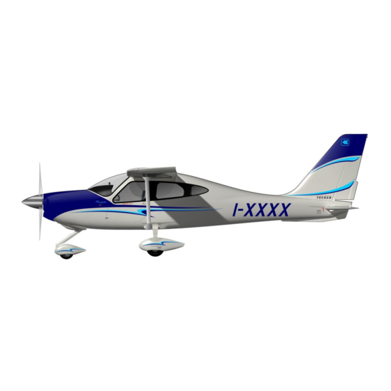
Page 1 - 3 1. INTRODUCTION The Aircraft Flight Manual has been prepared to provide pilots and instructors with information for the safe and efficient operation of this aeroplane. This manual also contains supplemental data supplied by the aeroplane manufac- turer. - Page 14 Page 1 - 4 4. THREE-VIEW AND DIMENSIONS Figure 1 – General views Edition, Rev.0 Section 1 – General THREE-VIEW AND DIMENSIONS...
- Page 15 Page 1 - 5 Dimensions Overall dimensions Wing Span …..…………………………….. 10.30 m / 33.79 ft Overall Length ……………………………. 7.97 m / 26.15 ft Overall height ……………………………... 2.64 m / 8.66 ft Stabilator Span ……………………………. 3.35 m / 10.99 ft Wing Wing surface ..……………………………..
- Page 16 Page 1 - 6 5. ENGINE Manufacturer …………………………… Lycoming Engines Model …………………………………... IO-360-M1A Type Certificate ………………………... EASA TCDS no. IM.E.032 Engine type …………………………….. Fuel injected (IO), direct drive, four cylinder horizontally opposed, air cooled with down exhaust outlets. Maximum power ……. 134.0 kW (180 hp) @ 2700 rpm Maximum continuous power …………...
-
Page 17: Specific Loadings
Page 1 - 7 7. FLIGHT CONTROL SURFACES TRAVEL Ailerons Up 19°; Down 14 ° ( 2°) Stabilator* Up 6°; Down 17° ( 2°) Stabilator trim tab Up 3°; Down 15° ( 1°) Rudder RH 25°; LH 25° ( 2°) Rudder trim tab RH 20°;... - Page 18 Page 1 - 8 INTENTIONALLY LEFT BLANK Edition, Rev.0 Section 1 – General TERMINOLOGYSP ECIFIC LOADINGS...
- Page 19 Page 1 - 9 9. ACRONYMS AND TERMINOLOGY KCAS Calibrated Airspeed is the indicated airspeed expressed in knots, corrected taking into account the errors related to the instrument itself and its installation. KIAS Indicated Airspeed is the speed shown on the airspeed indicator and it is expressed in knots.
- Page 20 Page 1 - 10 Meteorological terminology International Standard Atmosphere: is the air atmospheric standard condition at sea level, at 15 °C (59 °F) and at 1013.25 hPa (29.92 inHg). Official atmospheric pressure at airport level: it indicates the air- craft absolute altitude with respect to the official airport level. Theoretical atmospheric pressure at sea level: is the atmospheric pressure reported at the medium sea level, through the standard air pressure-altitude relationship, starting from the airport QFE.
- Page 21 Page 1 - 11 Aircraft performance and flight planning terminology Crosswind Velocity is the velocity of the crosswind component for the which adequate control of the air- plane during takeoff and landing is assured. Usable fuel is the fuel available for flight planning. Unusable fuel is the quantity of fuel that cannot be safely used in flight.
- Page 22 Maximum Landing Weight is the maximum weight approved for the landing touchdown (for P2010 it is equiva- lent to the Maximum Takeoff Weight). Edition, Rev.0 Section 1 – General ACRONYMS AND TERMINOLOGY...
- Page 23 Page 1 - 13 INTENTIONALLY LEFT BLANK Edition, Rev.0 Section 1 – General...
-
Page 24: Unit Conversion Chart
Page 1 - 14 10. UNIT CONVERSION CHART MOLTIPLYING YIELDS EMPERATURE Fahrenheit [°F] Celsius [°C] Celsius [°C] Fahrenheit [°F] ORCES Kilograms [kg] 2.205 Pounds [lbs] Pounds [lbs] 0.4536 Kilograms [kg]... - Page 25 Page 1 - 15 11. LITRES / US GALLONS CONVERSION CHART Litres US Gallons US Gallons Litres 11.4 15.1 22.7 30.3 37.9 10.6 45.4 11.9 53.0 13.2 60.6 15.9 68.1 18.5 75.7 21.1 83.3 23.8 90.9 26.4 98.4 29.1 106.0 31.7 113.6 34.3...
- Page 26 Page 1 - 16 INTENTIONALLY LEFT BLANK Edition, Rev.0 Section 1 – General...
- Page 27 Page 2 - 1 SECTION 2 – LIMITATIONS INDEX INTRODUCTION ................3 AIRSPEED LIMITATIONS .............. 5 AIRSPEED INDICATOR MARKINGS ..........6 POWERPLANT LIMITATIONS ............7 FUEL ..................... 8 LUBRICANT .................. 8 PAINT ................... 9 PROPELLER .................. 9 MAXIMUM OPERATING ALTITUDE ..........9 AMBIENT TEMPERATURE ............
- Page 28 Page 2 - 2 INTENTIONALLY LEFT BLANK Edition, Rev.0 Section 2 – Limitations...
- Page 29 Page 2 - 3 1. INTRODUCTION Section 2 includes operating limitations, instrument markings and basic placards necessary for safe operation of the aeroplane, its engine and standard systems and equipment. Edition, Rev.0 Section 2 – Limitations INTRODUCTION...
- Page 30 Page 2 - 4 INTENTIONALLY LEFT BLANK Edition, Rev.0 Section 2 – Limitations...
-
Page 31: Airspeed Limitations
Page 2 - 5 2. AIRSPEED LIMITATIONS The following table addresses the airspeed limitations and their operational signifi- cance: AIRSPEED KIAS KCAS REMARKS Never exceed speed Do not exceed this speed in V NE any operation. Maximum Structural Cruising Do not exceed this speed V NO Speed except in smooth air, and... -
Page 32: Airspeed Indicator Markings
Page 2 - 6 3. AIRSPEED INDICATOR MARKINGS Airspeed indicator markings and their colour code are explained in the following table. MARKING KIAS EXPLANATION 50 – 91 White arc Positive Flap Operating Range (lower limit is V , at specified maximum weight and upper limit is the maximum speed permissi- ble with landing flaps extension). -
Page 33: Powerplant Limitations
Page 2 - 7 4. POWERPLANT LIMITATIONS Following table reports the operating limitations the installed engine: : Lycoming Engines NGINE MANUFACTURER : IO-360-M1A NGINE MODEL AXIMUM POWER Max Power Max rpm. (hp) Prop. rpm Max. T.O. 2700 2700 Max. Cont. Temperatures: Max CHT ……………………………………….. - Page 34 Page 2 - 8 5. FUEL 120 litres each one (31.7 US gallons) ANKS 240 litres (63.4 US gallons) AXIMUM CAPACITY 231 litres (61 US gallons) AXIMUM USABLE FUEL AVGAS Grade 91/96 or 100 LL (ASTM D910) PPROVED FUEL For additional information, refer to Lycoming Service Instruction No. 1070, latest issue. 6.
-
Page 35: Maximum Operating Altitude
Page 2 - 9 7. PAINT To ensure that the temperature of the composite structure does not exceed limits, the outer surface of the aeroplane must be painted with white paint, except for areas of registration marks, placards, and ornament. Refer to Aircraft Maintenance Manual (AMM), ATA Chapter 4 and 51, for specific paint requirements. -
Page 36: Powerplant Instrument Markings
Page 2 - 10 11. POWERPLANT INSTRUMENT MARKINGS Powerplant instrument markings and their colour code significance are shown below: RED ARC WHITE ARC GREEN ARC YELLOW ARC RED ARC INSTRUMENT Safe Minimum Advisory Caution Maximum limit limit operation PROPELLER 950-2700 0-950 2700-2800 OIL TEMP. -
Page 37: Center Of Gravity Range
Page 2 - 11 13. WEIGHTS Condition Weight Maximum takeoff weight 1160 kg 2557 lb Maximum landing weight 1160 kg 2557 lb Maximum baggage weight 40 kg 88 lb Baggage Compartment Weight Maximum weight 40 kg 88 lb Maximum specific pressure 0.72 kg/dm 14.9 lb/ft NOTE... -
Page 38: Approved Maneuvers
Page 2 - 12 16. APPROVED MANEUVERS The aircraft is certified in Normal Category in accordance with EASA CS-23and FAA 14 CFR part 23 regulations. Non aerobatic operations include: Any manoeuvre pertaining to “normal” flight Stalls (except whip stalls) ... - Page 39 Page 2 - 13 18. KINDS OF OPERATION EQUIPMENT LIST (KOEL) This paragraph reports the KOEL table, concerning the equipment list required on board under CS-23 and Far-23 regulations to allow flight operations in VFR Day/Night and IFR Day/Night. Flight in VFR Day/Night and IFR is permitted only if the prescribed equipment is installed and operational.
- Page 40 Page 2 - 14 INTENTIONALLY LEFT BLANK Edition, Rev.1 Approved Section 2 – Limitations...
-
Page 41: Limitations Placards
Page 2 - 15 19. LIMITATIONS PLACARDS Hereinafter limitation placards, related to the operating limitations, are placed in plain view on the pilot. 19.1. PEED LIMITATIONS On the left side instrument panel, above on the left, it is placed the following plac- ard reporting the speed limitations: 19.2. - Page 42 Page 2 - 16 19.4. AGGAGE OMPARTMENT PLACARD Behind the baggage compartment door the following placard is placed: Edition, Rev.1 Approved Section 2 – Limitations LIMITATIONS PLACARDS...
- Page 43 Page 3 - 1 SECTION 3 – EMERGENCY PROCEDURES INDEX 1. Introduction ..................3 2. Failures indicated on the annunciation window ......5 2.1. Alternator failure ................5 2.2. Pitot heating system failure ............6 3. G1000 System Failures ..............7 3.1.
- Page 44 Page 3 - 2 8.2. Engine fire during takeoff ............21 8.3. Engine fire in flight ..............21 8.4. Electrical smoke in cabin on the ground ........22 8.5. Electrical smoke in cabin during flight ........22 9. Recovery from unintentional spin ..........23 10.
- Page 45 Page 3 - 3 1. I NTRODUCTION Section 3 includes checklists and detailed procedures for coping with various types of emergency conditions that could arise. Before operating the aircraft, the pilot should become thoroughly familiar with the present manual and, in particular, with the present Section. Further, a contin- ued and appropriate training should be provided.
- Page 46 Page 3 - 4 INTENTIONALLY LEFT BLANK Edition, Rev.0 Section 3 – Emergency procedures...
-
Page 47: Alternator Failure
Page 3 - 5 2. F AILURES INDICATED ON THE ANNUNCIATION WINDOW The annunciator window is integrated in the GARMIN G1000. The colours are as follows: GREEN: to indicate that pertinent device is turned ON AMBER: to indicate no-hazard situations which have to be considered and which require a proper crew action RED: to indicate emergency conditions... -
Page 48: Pitot Heat
Page 3 - 6 2.2. ITOT HEATING SYSTEM FAILURE Annunciation window Alert window PITOT HEAT ON Pitot heat on PITOT HEAT Pitot heat When the Pitot Heating system is activated, the green PITOT HEAT ON advi- sory light turns on and the amber PITOT HEAT caution light turns OFF, indi- cating that the Pitot Heating system is functioning properly. - Page 49 Page 3 - 7 3. G1000 S YSTEM AILURES 3.1. OSS OF INFORMATION DISPLAYED When a LRU or a LRU function fails, a large red „X‟ is typically displayed on the display field associated with the failed data. In most of cases, the red “X” annunciation is accompanied by a message advisory alert issuing a flashing ADVISORY Softkey NOTE annunciation which, once selected, acknowledges the presence...
- Page 50 Page 3 - 8 3.3. OSS OF ATTITUDE INFORMATION ATTITUDE FAIL ON DISPLAY FIELD Display system is not receiving attitude information from AHRS. INSTRUCTION: revert to standby instrument 3.4. OSS OF ALTITUDE INFORMATION ALTITUDE FAIL ON DISPLAY FIELD Display system is not receiving altitude input from Air Data Computer.
- Page 51 Page 3 - 9 3.5. OSS OF VERTICAL SPEED INFORMATION VERT SPEED FAIL ON DISPLAY FIELD Display system is not receiving vertical speed input from Air Data Computer. INSTRUCTION: determine vertical speed on the basis of altitude information 3.6. OSS OF HEADING INFORMATION ON DISPLAY FIELD Display system is not receiving valid heading input from AHRS.
-
Page 52: Display Failure
Page 3 - 10 3.7. ISPLAY FAILURE In the event of a display failure, the G1000 System automatically switches to re- versionary (backup) mode. In reversionary mode, all important flight information is presented on the remaining display in the same format as in normal operating mode. - Page 53 Page 3 - 11 4. E NGINE SECURING Following procedure is applicable to shut-down the engine in flight: Throttle Lever IDLE Ignition key Fuel Selector Electrical fuel pump Generator switch 5. A IRCRAFT EVACUATION With the engine secured and propeller stopped (if practical): Parking brake Seat belts Unstrap...
- Page 54 Page 3 - 12 INTENTIONALLY LEFT BLANK Edition, Rev.0 Section 3 – Emergency procedures...
- Page 55 Page 3 - 13 6. E NGINE FAILURES 6.1. NGINE FAILURE DURING TAKEOFF RUN If engine fails before rotation: ABORT TAKE OFF 1. Throttle Lever ………………………….. IDLE (fully out and hold) 2. Mixture …………………………………. CUT OFF 3. Brake ……………………………………. As required With aircraft stopped 4.
-
Page 56: Propeller Overspeed
Page 3 - 14 6.3. ROPELLER OVERSPEED In case of propeller overspeeding in flight, apply following procedure: 1. Throttle Lever ……………. REDUCE power 2. Mixture Lever ……………. As required 3. RPM indicator .…………… CHECK If it is not possible to decrease propeller rpm, land as soon as possible applying Forced landing procedure. - Page 57 Page 3 - 15 6.5. LIMIT EXCEEDANCE If CHT exceeds maximum limit (500°F): 1. Throttle Lever ……………. REDUCE power as practical 2. Mixture Lever ……………. Rich as required 3. CHT ……………………… Verify decreasing If CHT stabilizes in the green arc: 4.
-
Page 58: Low Oil Pressure
Page 3 - 16 6.7. IL PRESSURE LIMITS EXCEEDANCE OW OIL PRESSURE If oil pressure is under the lower limit (25 psi) 1. Throttle Lever …………… REDUCE to minimum practical 2. Mixture Lever ...………….. as required 3. OIL TEMP ………………… CHECK within limits 4. - Page 59 Page 3 - 17 6.8. OW FUEL PRESSURE If fuel pressure decreases below the lower limit (14 psi) 1. Electric fuel pump………... ON 2. Fuel selector valve………... Select opposite fuel tank if NOT empty 3. Fuel quantity ……………... CHECK If fuel pressure doesn‟t build up: 1.
-
Page 60: Defective Engine Controls
Page 3 - 18 6.10. EFECTIVE ENGINE CONTROLS Defective Mixture Control Cable 1. Maintain altitude to the nearest airfield 2. During descent, check engine behaviour to a higher power setting. A lean mixture can lead to engine roughness and loss of power. Landing approach must be planned accordingly. - Page 61 Page 3 - 19 7. I NFLIGHT ENGINE RESTART 7.1. ROPELLER WINDMILLING In case of engine shutdown, propeller will keep windmilling and will not stop, preventing the use of ignition key. Engine inflight restart must be performed without using ignition key until propeller is windmilling in order to avoid possible engine damages.
- Page 62 Page 3 - 20 INTENTIONALLY LEFT BLANK Edition, Rev.0 Section 3 – Emergency procedures...
- Page 63 Page 3 - 21 8. S MOKE AND FIRE 8.1. NGINE FIRE ON THE GROUND 1. Mixture ……………………………………… CUT OFF 2. Cabin heat and defrost …………………….. 3. Fuel Selector ………………………………. . 4. Ignition key ………………………………… 5. Fuel pump…………………………………... 6. MASTER SWITCH ……………………….. 7.
- Page 64 Page 3 - 22 8.4. LECTRICAL SMOKE IN CABIN ON THE GROUND 1. MASTER SWITCH ………………………….. 2. Generator Switch …………………………..3. Cabin heat and defrost ………………………. 4. Throttle Lever ………………………………… IDLE 5. Ignition key …………………………………… 6. Fuel Selector ………………………………….. With propeller stopped, evacuate the aircraft 8.5.
-
Page 65: Recovery From Unintentional Spin
Page 3 - 23 9. R ECOVERY FROM UNINTENTIONAL SPIN If unintentional spin occurs: …………………………… Idle 1. Throttle 2. Rudder …………………………………… Fully opposite to the direction of spin 3. Control Yoke …………………………….. Centralize and hold neutral When rotation stops: 4. Rudder …………………………………… Neutral 5. - Page 66 Page 3 - 24 INTENTIONALLY LEFT BLANK Edition, Rev.0 Section 3 – Emergency procedures...
- Page 67 Page 3 - 25 10. O THER EMERGENCIES 10.1. OSS OF SSENTIAL In case of loss of essential bus, the following will be lost (related breakers are listed): FLAP ACTUATOR COM1 PITOT HEAT GPS1/NAV1 STROBE LIGHT LANDING LIGHT FUEL PUMP AHRS FIELD STALL WARNING...
- Page 68 Page 3 - 26 10.3. LECTRICAL SYSTEM OVERALL FAILURE In case of electrical system overall failure, apply following procedure: ……………………. OFF 1. MASTER SWITCH …………………… OFF 2. Generator Switch ……………………. ON 3. MASTER SWITCH …………………… ON 4. Generator Switch If failure persists Land as soon as possible Standby instrument is still available, providing the internal bat- NOTE...
- Page 69 Page 3 - 27 10.5. NINTENTIONAL FLIGHT INTO ICING CONDITIONS Pitot heat ……...………….. Immediately fly away from icing conditions (changing altitude and direc- tion of flight, out and below of clouds, visible moisture, precipitations). Control surfaces …………. Move continuously to avoid locking Throttle…………………….
- Page 70 Page 3 - 28 10.7. LECTRICAL UDDER RIM CONTROL FAILURE Trim Runaway In event of trim runaway: Speed: adjust to control aircraft without excessive pedal force Rudder: As required Land aircraft as soon as practical. Trim Jamming Should trim control be jammed / inoperative: Breaker: CHECK IN Speed:...
-
Page 71: Landing Emergencies
Page 3 - 29 11. L ANDING EMERGENCIES 11.1. ORCED LANDING WITHOUT ENGINE POWER Preparation: Flaps…………………………………. Best Glide Speed ……………………. 85KTS Radio ………………………………… Transmit MAYDAY giving location and intentions Transponder …………………………. 7700 If off airport, ELT …………………… Find a suitable place to land safely, plan to approach it upwind Throttle Lever ………………………. - Page 72 Page 3 - 30 11.3. ANDING WITH NOSE LANDING GEAR TIRE DEFLATED Pre-landing checklist: Complete Flaps: Land Land and maintain aircraft NOSE HIGH attitude as long as possible. As aircraft stops 4. Engine securing: Perform(see Para. 5) 5. Airplane evacuation: Perform(see Para 4) 11.4.
- Page 73 Page 4 - 1 SECTION 4 – NORMAL PROCEDURES INDEX INTRODUCTION ..................3 IFR flight: training pre-requisites and incremental exposition to G1000 suite ..............4 AIRSPEEDS FOR NORMAL OPERATIONS ........7 PRE-FLIGHT INSPECTION ..............9 4.1. Cabin Inspection ................9 4.2.
- Page 74 Page 4 - 2 INTENTIONALLY LEFT BLANK Edition, Rev. 0 Section 4 – Normal procedures...
- Page 75 Page 4 - 3 INTRODUCTION Section 4 describes checklists and recommended procedures for the conduct of normal operations for P2010 aircraft. Edition, Rev. 0 Section 4 – Normal procedures INTRODUCTION...
- Page 76 Page 4 - 4 2. IFR FLIGHT TRAINING PRE REQUISITES AND INCREMENTAL EX- G1000 POSITION TO SUITE The aircraft is fully equipped with a Garmin G1000 avionic suite that integrates radio aids navigation with GPS navigation, providing an outstanding capability to support IFR flight, from basic instrument training to complex IFR scenario.
- Page 77 Page 4 - 5 NOTE The necessity to correct or modify flight plans in the Garmin G1000 under these conditions may distract pilots from basic handling causing deviations from as- signed parameters, so careful attention must be exercised to avoid deviations on flying parameters.
- Page 78 Page 4 - 6 INTENTIONALLY LEFT BLANK Edition, Rev. 0 Section 4 – Normal procedures...
-
Page 79: Airspeeds For Normal Operations
Page 4 - 7 3. AIRSPEEDS FOR NORMAL OPERATIONS The following airspeeds are those which are significant for normal operations. FLAPS 1160 kg (2557 lb) Rotation Speed (V 60 KIAS Best Angle-of-Climb Speed (V 65 KIAS Best Angle-of-Climb Speed (V 0°... - Page 80 Page 4 - 8 INTENTIONALLY LEFT BLANK Edition, Rev. 0 Section 4 – Normal procedures...
-
Page 81: Pre-Flight Inspection
Page 4 - 9 4. PRE-FLIGHT INSPECTION Before each flight, it is necessary to carry out a complete aircraft check including a cabin inspection followed by an external inspection, as below detailed. 4.1. ABIN NSPECTION Aircraft documents (ARC, Certificate of Airworthiness, Noise certificate, Radio COM certificate, AFM): check current and on board Weight and balance: calculate (ref. -
Page 82: Aircraft Walk - Around
Page 4 - 10 4.2. IRCRAFT AROUND To perform the aircraft walk-around, carry out the checklists according to the pattern shown in Figure 4-1. Visual inspection is defined as follows: check for defects, cracks, detachments, excessive play, unsafe or improper installation as well as for general condition. - Page 83 Page 4 - 11 Figure 4.1 Left fuel filler cap CHECK desired fuel level (use graduated dipstick). Drain the left fuel tank sump by quick drain valve using a cup to collect fuel (drainage operation must be carried with the aircraft parked on a level surface). Check for water or other contaminants.
- Page 84 Page 4 - 12 Left main landing gear CHECK inflation, tire condition, alignment, fuselage skin condition. Check fuselage skin status, tire status (cuts, bruises, cracks and excessive wear), slippage markers integrity, gear structure and brakes hoses: there should be no sign of hydraulic fluid leakage. Stabilator, tab and rear light CHECK stabilator leading edge.
- Page 85 Page 4 - 13 Propeller and spinner condition CHECK for nicks, cracks, dents and other de- fects, propeller should rotate freely. Check fixing and lack of play between blades and hub. Check the engine cowling surface conditions, then open engine inspection doors and perform the following checks: a) Nacelle inlets and exhausts openings must be free of obstructions.
- Page 86 Page 4 - 14 INTENTIONALLY LEFT BLANK Edition, Rev. 0 Section 4 – Normal procedures...
- Page 87 Page 4 - 15 5. CHECKLISTS 5.1. EFORE TARTING ENGINE FTER REFLIGHT NSPECTION 1. Seat position and safety belts: adjust 2. Flight controls: operate full stroke checking for movement smoothness, free of play and friction. 3. Parking brake: engage 4. Throttle friction: adjust 5.
-
Page 88: Engine Starting
Page 4 - 16 5.2. NGINE TARTING (a) Cold engine Engine throttle: 1cm (1/2 inch) above idle Fuel selector valve: select the tank with less fuel Electric fuel pump: ON Mixture: full open for 3 – 5” (positive fuel flow indication) then CUT-OFF Propeller area: check that area is clear of persons / objects Check to insure no person or object is present in the area close to the propeller. -
Page 89: Before Taxiing
Page 4 - 17 (b) Warm engine Engine throttle: IDLE Fuel selector valve: select the tank with less fuel Electric fuel pump: ON Propeller area: check for area clear of persons / objects Check to insure no person or object is present in the area close to the propel- ler. - Page 90 Page 4 - 18 5.4. AXIING 1. Parking brake: Release 2. Brakes: check 3. Flight instruments: check altimeter. NOTE Avoid prolonged idling during taxi. Alternator lights may appear when reducing engine RPM below 950 RPM (yellow arc). The light will stay ON until RPM is increased above. During taxi, it is recommended to maintain propeller speed at 1000RPM or above in order to preserve a full loaded battery, minimise annunciator nuisance and assure max- CAUTION...
- Page 91 Page 4 - 19 5.5. EFORE TAKEOFF 1. Parking brake: brake pedal press, ON 2. Engine instruments: Check within limits 3. ALT OUT caution: OFF (check) 4. Electric Fuel pump: ON 5. Fuel selector valve: select the fullest tank 6. Fuel pressure: check 7.
- Page 92 Page 4 - 20 5.6. AKEOFF For 5000ft density altitude and above, or high ambient temperatures, a FULL RICH mixture may cause rough running of the engine or a loss of performance. The mixture may be ad- justed to obtain smooth engine operations. NOTE Lean to maximum RPM at Full Throttle prior to take-off where airports are at 5000ft density altitude or higher.
- Page 93 Page 4 - 21 5.7. LIMB Due to position of fuel sensors, during climb fuel gauges in cockpit will indicate a fuel NOTE quantity slightly lower than the real amount. Regaining level flight will immediately restore correct indications. For 5000ft density altitude and above, or high ambient temperatures, a FULL RICH mixture may cause rough running of the engine or a loss of performance.
- Page 94 Page 4 - 22 5.8. RUISE 1. Power: set performance as required, refer to table in section 5 of AFM 2. Fuel tank selector: as required to maintain symmetric balance 3. Mixture: set in accordance with following para 5.9 To optimize engine life, the cylinder head temperature (CHT) should lie NOTE between 150°F and 400°F in continuous operation, and not rise above 435°F in fast cruise.
- Page 95 Page 4 - 23 5.10. ESCENT Due to position of fuel sensors, during descent fuel gauges in cockpit will indicate a fuel NOTE quantity slightly higher than the real amount. Regaining level flight will immediately re- store correct indications. 1. Mixture control: slowly full rich 2.
- Page 96 Page 4 - 24 5.11. EFORE LANDING Electric fuel pump: ON Fuel valve: select the fullest tank Landing Light: ON On downwind, leg abeam touch down point: Flaps: set T/O (below 90KIAS) Expect to adjust pitch trim (pitch down) when extending flaps to T/O or NOTE LAND Approach speed: set...
- Page 97 Page 4 - 25 5.15. NGINE SHUT DOWN Parking brake: set Keep engine running at 1200 propeller rpm for about one minute in order to reduce latent heat. Avionic equipment: OFF Throttle: idle Magnetos: Check OFF – BOTH Mixture: closed Ignition key: OFF, key extracted Strobe light: OFF Avionic Master: OFF...
- Page 98 Page 4 - 26 5.17. FLIGHT IN RAIN Performance deteriorates in rain; this applies particularly to take-off distance and maximum Horizontal speed. The effect on flight characteristics is minimal. 5.18. REFUELLING Before refuelling, the airplane must be connected to electrical ground. 5.19.
- Page 99 Page 5 - 1 SECTION 5 - PERFORMANCE INDEX Introduction ............2 Use of Performance Charts ........2 Airspeed Indicator System Calibration ....3 ICAO Standard Atmosphere ........5 Stall speed ............6 Crosswind ............. 7 Take-Off performances ......... 8 Take-off Rate of Climb ........
-
Page 100: Use Of Performance Charts
Page 5 - 2 1. I NTRODUCTION This section provides all necessary data for an accurate and comprehensive planning of flight activity from take-off to landing. Data reported in graphs and/or in tables were determined using: “Flight Test Data” under conditions prescribed by EASA CS-23 regulation ... -
Page 101: Airspeed Indicator System Calibration
Page 5 - 3 3. A IRSPEED NDICATOR YSTEM ALIBRATION Normal Static Source Graph shows calibrated airspeed V as a function of indicated airspeed V Airspeed Indication System Calibration Flap UP Flap T/O Flap LN Calibrated Airspeed [KCAS] . 5-1. C ALIBRATED VS NDICATED IRSPEED... - Page 102 Page 5 - 4 Alternate Static Source Alternate Static Air Open Vents Open Vents and Hot Air Open [kn] [ft] [kn] [ft] [kn] [ft] Pressure Altitude FLAP UP [ft] [kn] 1020 1010 1020 1020 1030 1020 1030 1020 1020 1040 1030 1030 FLAP T/O...
- Page 103 Page 5 - 5 4. ICAO S TANDARD TMOSPHERE . 5-2. ICAO C HART Examples: Scope Given Find A: Pressure altitude = 1600ft → C: Density Altitude = 2550ft Density Altitude: B: Temperature = 20°C → E: ISA Air Temperature = 12°C ISA Temperature: D: Pressure altitude = 1600ft Edition, Rev.
-
Page 104: Stall Speed
Page 5 - 6 5. S TALL SPEED Weight: 1160 kg (2557 lb) Throttle Lever: IDLE CG: Most Forward (19%) No ground effect TALL PEED EIGHT NGLE 0° LAPS LAPS LAPS [kg] [deg] KIAS KCAS KIAS KCAS KIAS KCAS ([lb]) 1160 (2557) (FWD C.G.) - Page 105 Page 5 - 7 6. C ROSSWIND Maximum demonstrated crosswind is 12 kts. Example: Given Find Wind direction ( Headwind = 17.5 kts with respect to ) = 30° aircraft longitudinal axis Wind speed = 20 kts Crosswind = 10 kts .
-
Page 106: Take -Off Performances
Page 5 - 8 7. T FF PERFORMANCES To account for likely in service performance variations apply a NOTE factored to distances of 1.10 Weight = 1160 kg (2557 lb) Corrections Headwind: - 10 m (33 ft) for each kn Flaps: T/O Speed at Lift-Off = 60 KIAS Tailwind: +20 m (66 ft) for each kn... - Page 107 Page 5 - 9 Weight = 1060 kg (2337 lb) Corrections Headwind: - 10 m (33 ft) for each kn Flaps: T/O Speed at Lift-Off = 60 KIAS Tailwind: + 20 m (66 ft) for each kn Speed Over 50ft Obstacle = 65 KIAS Grass Runway: + 10% to Ground Roll Throttle Lever: Full Forward Runway slope: +10% to Ground Roll for each +1%...
- Page 108 Page 5 - 10 Weight = 960 kg (2116 lb) Corrections Headwind: - 10 m (33 ft) for each kn Flaps: T/O Speed at Lift-Off = 60 KIAS Tailwind: + 20 m (66 ft) for each kn Speed Over 50ft Obstacle = 65 KIAS Grass Runway: + 10% to Ground Roll Throttle Lever: Full Forward Runway slope: +10% to Ground Roll for each +1%...
- Page 109 Page 5 - 11 8. T ATE OF LIMB To account for likely in service performance variations apply a NOTE factored to rate of climb of 0.90 Full Forward Throttle Lever: Flaps: Take-Off Rate of Climb [ft/min] Climb Pressure Weight Speed Altitude Temperature [°C]...
- Page 110 Page 5 - 12 9. E OUTE ATE OF LIMB To account for likely in service performance variations apply a NOTE factored to rate of climb of 0.90 Full Forward Throttle Lever: Flaps: UP Rate of Climb [ft/min] Climb Pressure Weight Speed Altitude...
-
Page 111: Cruise Performance
Page 5 - 13 10. C RUISE ERFORMANCE Weight: 1160 kg (2557 lb) Corrections Mixture: FULL RICH Best Power: -10% to Full Rich F.C. Best Economy: -20% to Full Rich F.C. CORRECTIONS Fuel Specific KTAS Endurance Range Consumption Range For each +15 °C of OAT -2.5% For each -15 °C of OAT For -100 kg (-220 lb) of weight... - Page 112 Page 5 - 14 Weight: 1160 kg (2557 lb) Corrections Mixture: FULL RICH Best Power: -10% to Full Rich F.C. Best Economy: -20% to Full Rich F.C. CORRECTIONS Fuel Specific KTAS Endurance Range Consumption Range For each +15 °C of OAT -2.5% For each -15 °C of OAT For -100 kg (-220 lb) of weight...
- Page 113 Page 5 - 15 11. L ANDING PERFORMANCES To account for likely in service performance variations apply a NOTE factored to distances of 1.67 Weight = 1160 kg (2557 lb) Corrections Headwind: - 4 m (-13 ft) for each kn Flaps: LAND Short Final Approach Speed = 66 KIAS Tailwind: + 13 m(+43 ft) for each kn...
- Page 114 Page 5 - 16 12. B ALKED ANDING ERFORMANCE To account for likely in service performance variations apply a NOTE factored to rate of climb and to angle of climb of 0.90 Throttle Lever: Full Forward Flaps: LAND Speed: 67 KIAS Steady Gradient of Climb [%] Pressure Weight...
-
Page 115: Noise Data
Page 5 - 17 13. N OISE Noise level, determined in accordance with ICAO/Annex 16 6 Ed., July 2011, Vol. I°, Chapter 10 and 14 CFR Part 36, is 77.576 dB(A). NOTE: No determination has been made by the Federal Aviation Administration that the noise levels of this aircraft are or should be acceptable or unacceptable for operation at, into, or out of, any airport. - Page 116 Page 5 - 18 INTENTIONALLY LEFT BLANK Edition, Rev. 0 Section 5 - Performances...
- Page 117 Page 6 - 1 SECTION 6 – WEIGHT AND BALANCE INDEX 1. INTRODUCTION ................3 2. WEIGHING PROCEDURES ............. 4 2.1. Preparation ................4 2.2. Levelling ..................4 2.3. Weighing ..................4 2.4. Determination of C.G. location ..........4 2.5. Weighing record................. 5 2.6.
- Page 118 Page 6 - 2 INTENTIONALLY LEFT BLANK Edition, Rev. 0 Section 6 – Weight and Balance...
- Page 119 Page 6 - 3 1. INTRODUCTION This section describes the procedure for establishing the basic empty weight and the moment of the aircraft. Loading procedure information is also provided. Aircraft must be operated in accordance with the limits con- NOTE cerning the maximum takeoff weight and CG excursion as re- ported in Flight Manual Section 2.
-
Page 120: Weighing Procedures
Page 6 - 4 2. WEIGHING PROCEDURES 2.1. REPARATION Carry out weighing procedure inside closed hangar Remove from cabin any object unintentionally left Make sure Flight Manual and mandatory documents are on board Align nose wheel Drain fuel via the specific drain valve Oil and hydraulic fluid at the operating levels Move sliding seats to most forward position Raise flaps to fully retracted position... -
Page 121: Weighing Record
Page 6 - 5 2.5. EIGHING RECORD Model P2010 S/N:________ Weighing no. ____ Date:_________ Datum: leading edge vertical DATUM BALANCE LH/RH BALANCE NLG kg or lbs meters or feet Nose wheel weight W Plumb bob distance LH wheel LH wheel weight... - Page 122 Page 6 - 6 2.6. (II) EIGHING RECORD Model P2010 S/N:________ Weighing no. ____ Date:_________ Datum: leading edge vertical DATUM BALANCE LH/RH BALANCE NLG kg or lbs meters or feet Nose wheel weight W Plumb bob distance LH wheel LH wheel weight...
- Page 123 Page 6 - 7 3. WEIGHTS AND C.G. C.G. position can be defined by means of the chart below. The pilot is responsible for ensuring the correct useful load loading. Figure 1 Example A/C empty mass moment kg*m (1360 lb*ft) A/C empty mass kg (1687 lb) Occ.
- Page 124 Page 6 - 8 3.1. C.G. CALCULATION SAMPLES 3.1.1. [kg] Arm [mm] Moment [kg*mm] 775 (1708 lb) Empty weight 309 (1,01 ft) 239475 (1726 lb*ft) 23,4% CoG pos. USEFUL LOAD 80 (176 lb) 133 (0,44 ft) 10640 (77 lb*ft) Pilot 133 (0,44 ft) Pilot 1057 (3,47 ft)
-
Page 125: Baggage Loading
Page 6 - 9 4. BAGGAGE LOADING The baggage loading in the dedicated compartment must be carried out in accord- ance with diagram addressed on PAR. 03 and with C.G. excursion and weight lim- itations reported in Section 2. Pilot is provided with a red tie-down net and snap fasteners allowing for securing the loads on the compartment floor. - Page 126 Page 6 - 10 INTENTIONALLY LEFT BLANK Edition, Rev. 0 Section 6 – Weight and Balance...
-
Page 127: Equipment List
Page 6 - 11 5. EQUIPMENT LIST The following is a list of equipment which may be installed in the P2010. The items marked with an "X" were installed on the airplane described at the be- ginning of the list and they are included in the Basic Empty Weight. - Page 128 Page 6 - 12 _____ QUIPMENT LIST IRCRAFT S EIGHT [kg] ESCRIPTION ([lb]) ([ft]) NSTRUMENTATION GARMIN G1000 IFDS 0.73 -0.69 6420302-1 MD 302 MID Continent (1.61) (-2.26) -0.69 C2400L4P Compass (0.88) (-2.26) -0.69 Pitch trim indicator – UMA instruments N0911S0U2DR00W (0.22) (-2.26) -0.69...
- Page 129 Page 6 - 13 _____ QUIPMENT LIST IRCRAFT S EIGHT [kg] ESCRIPTION ([lb]) ([ft]) (4.4) LIGHTS: 0.23 Nav/POS/Strobe Light SH wing - Ultragalactica Aveo AVE-WPST R/G-54G (2.2) (0.75) Rudder Nav Light – PosiStrobe CT AVE-POSW-62G (2.2) (18.04) -1.52 Landing/Taxy Light - WHELEN Mod 7167400 01-0771674-00 (4.4) (-4.99)
- Page 130 Page 6 - 14 INTENTIONALLY LEFT BLANK Edition, Rev. 0 Section 6 – Weight and Balance...
- Page 131 Page 7 - 1 SECTION 7 – AIRFRAME AND SYSTEMS DESCRIPTION INDEX INTRODUCTION ................2 AIRFRAME ..................2 2.1. Wing ......................2 2.2. Fuselage ...................... 3 2.3. Empennages ....................3 2.3.1. Horizontal Tail ..................... 3 2.3.1. Rudder Surface .................... 4 2.4.
- Page 132 Page 7 - 2 1. INTRODUCTION This section provides description and operation of the aircraft and its systems. 2. AIRFRAME P2010’s airframe can be divided in the following main groups, as highlighted below on fig- ure 7-1: 1) Wing 2) Fuselage...
-
Page 133: Horizontal Tail
2.2. USELAGE The P2010 fuselage is mainly made by carbon fibres composite materials. The fuselage is made by two main shells that are later assembled bonding the two main bod- ies and the floor (composite) and adding aluminium parts that allow the connection of the main landing gear, seats, wing and instrument panel. - Page 134 Page 7 - 4 2.3.1. UDDER URFACE The rudder structure is made-up by a single aluminium spar (1) and ribs (2). Aluminium skin panels (3) are riveted to the above elements. It is connected to the fin through two hing- es;...
-
Page 135: Main Landing Gear
Main gear wheels install type 6.00-6 tires inflated at 36 psi (2.5 bar). P2010 is provided with an independent hydraulically actuated brake system for each main wheel. A master cylinder is attached to each pilot’s rudder pedal. Hydraulic pressure, ap- plied via the master cylinders, enters the brake via lines connected to an inlet fitting on the caliper. - Page 136 Page 7 - 6 Left wheel brake Right wheel brake Left wheel brake Right wheel brake Master Cylinders Fig. 7-5. R UDDER PEDALS AND BRAKE MASTER CYLINDERS PILOT AND CO PILOT SIDE Fig. 7-6. BRAKE SYSTEM SCHEMATIC Edition, Rev. 0 Section 7 –...
-
Page 137: Nose Landing Gear
Page 7 - 7 2.5. OSE LANDING GEAR A Pivoting nose gear is attached to the firewall reinforcement plate. The shock absorber is fitted on the upper machined component and directly on the nose landing gear structure. In Figure 10 is shown: 1) Hydraulic shock absorber 2) Firewall 3) Nose wheel (5.00-5 tire, inflated at 32 PSI (2.2 BAR)) -
Page 138: Flight Controls
Page 7 - 8 3. FLIGHT CONTROLS Aircraft flight controls are operated through conventional stick and rudder pedals. Longitu- dinal control acts through a system of push-rods and is equipped with a trim tab. a cable control circuit is confined within the cabin and it is connected to a pair of push-pull rod sys- tems positioned in each main wing which control ailerons differentially. -
Page 139: Instrument Panel
Page 7 - 9 4. INSTRUMENT PANEL The instrument panel is divided in three areas: The left area holds Garmin G1000 PFD, a chronometer and the pitch trim indicator; The Central area holds the standby unit for PFI parameters, MD 302 suite, and the ELT button. - Page 140 Page 7 - 10 4.1. NGINE CONTROL LEVER Engine handling is via three levers: Throttle, RPM lever, Mixture control lever. They’re situated on the center control; the use of “front/forward” and “rear/backward” is defined in relation to the direction of flight (longitudinal). Mixture control lever This lever (right hand lever with red handle) controls the fuel-air mixture, which is supplied to the engine.
- Page 141 Page 7 - 11 4.2. LTERNATE Alternate Air knob is located on the central pedestal; when the knob is fully pulled outward from the instrument panel, injectors receive maximum hot air. During normal operation, the knob is set in OFF position. 4.3.
- Page 142 Page 7 - 12 INTENTIONALLY LEFT BLANK Edition, Rev. 0 Section 7 – Airframe and Systems description...
-
Page 143: Seats And Safety Harness
Page 7 - 13 5. SEATS AND SAFETY HARNESS In correspondence of the seats, three fitting points safety belts are provided; belt ad- justment is via the sliding buckle located on the belt metal hook. Seats are built with light allow tube structure and synthetic material cushioning. It is possible to perform following seat adjustments: Horizontal –... - Page 144 Page 7 - 14 6. DOORS P2010 features three doors: The main door is placed on the left side of the cabin, while on the right side there are two secondary doors, one on the front side and the other on the rear, used as an emergency exit.
- Page 145 Page 7 - 15 The internal handle can be locked, to avoid any chance of inadvertent opening, by means of a hook located nearby the handle itself and upper safety block, following pictures show the functioning. Fig. 7-12. H ANDLE LOCKING In case of rapid escapes or door handles malfunction, an emergency opening is provided on the rear side of the door.
- Page 146 Page 7 - 16 7. POWERPLANT 7.1. ENGINE Manufacturer …………………………… Lycoming Textron Model …………………………………... IO-360-M1A Type Certificate ………………………... EASA TCDS no. IM.E.032 Engine type …………………………….. Fuel injected (IO), direct drive, four cylinder horizontally opposed, air cooled with down exhaust outlets. Maximum power …….
- Page 147 Page 7 - 17 INTENTIONALLY LEFT BLANK Edition, Rev 0 Section 7 – Airframe and Systems description...
-
Page 148: Fuel System
The fuel system is designed to supply the reciprocating engine (Lycoming IO- 360-M1A) with the suitable flow rate and pressure according to engine limitations required by Lycoming operator manual. Following figure shows a schematic of the fuel system assy for P2010 airplane. LH Fuel qty indicator RH Fuel qty indicator... - Page 149 Page 7 - 19 INTENTIONALLY LEFT BLANK Edition, Rev 0 Section 7 – Airframe and Systems description...
-
Page 150: Electrical System
Page 7 - 20 9. ELECTRICAL SYSTEM Primary DC power is provided by an external alternator with a 28 VDC output, rated of 70 Amps @ 2700 rpm. During normal operations, it recharges the battery. Secondary DC power is provided by a lead type battery (GILL G-247) which pro- vides the energy necessary for feeding the essential electrical loads in the event of an alternator failure. -
Page 151: Stall Warning System
Page 7 - 21 .7-15. E LECTRICAL YSTEM RCHITECTURE 9.1. TALL ARNING YSTEM The aircraft is equipped with a stall warning system consisting of a sensor located on the right wing leading edge connected to a warning horn located near the in- strument panel. - Page 152 Page 7 - 22 9.2. VIONICS The avionic system installed on P2010 is mainly based on the integrated avionic suite Garmin G1000. The installed configuration is based on a two-screen layout. Primary flight information are displayed on the LH screen, namely PFD (Primary Flight Display).
-
Page 153: External Power Supply
Page 7 - 23 9.3. XTERNAL OWER UPPLY On the right side of the tail cone, an external power is present. Using this device it is possible to feed the electric system directly on the main bus bar, by an external power source. -
Page 154: Pitot-Static Pressure Systems
Page 7 - 24 10. PITOT-STATIC PRESSURE SYSTEMS The P2010 air speed/altitude indicating systems are connected with a Pitot-Static sys- tem based on a total pressure/Pitot probe (simple Pitot tube, heated for icing protec- tion) mounted on left wing strut and two static pressure ports connected in parallel and located in correspondence of engine firewall on left and right side of fuselage. - Page 155 Page 7 - 25 INTENTIONALLY LEFT BLANK Edition, Rev 0 Section 7 – Airframe and Systems description...
-
Page 156: External Lights
Page 7 - 26 11. LIGHTS 11.1. XTERNAL LIGHTS P2010 is equipped with the following external lights: 2 combined LED NAV/POS/Strobe integrated lights located on RH and LH wing; 1 POS/strobe combined light located on the rear (fixed on the rudder);... - Page 157 Page 7 - 27 11.2. NTERNAL LIGHTS On the cabin ceiling are located four map lights, two in the front area (pilot) and two in the rear area (passengers). In the central area of the cabin ceiling is located a spot light used to illuminate the pedestal during night flight operations.
-
Page 158: External Placards
Page 7 - 28 12. PLACARDS In addition to the limitation placards reported on Section 2, following placards are installed on the aircraft. Additionally, nearby the placards listed below (English lan- NOTE guage), directly translated placards in the language of the country in which the airplane is registered can be installed, when required by the specific NAA. - Page 159 Page 7 - 29 Static Ports: Lift Point: Wheel Fairing “No Step”: Edition, Rev 0 Section 7 – Airframe and Systems description PLACARDS...
- Page 160 Page 7 - 30 Allowed Fuel Placard: Tire Pressure placard: Stabilator degrees placard: Edition, Rev 0 Section 7 – Airframe and Systems description PLACARDS...
- Page 161 Page 7 - 31 Emergency exit placards: Edition, Rev 0 Section 7 – Airframe and Systems description PLACARDS...
-
Page 162: Internal Placards
Page 7 - 32 12.2. NTERNAL LACARDS Safety equipment placards: Edition, Rev 0 Section 7 – Airframe and Systems description PLACARDS... - Page 163 Page 7 - 33 ELT unit position placard: Breaker Panel placards: Edition, Rev 0 Section 7 – Airframe and Systems description PLACARDS...
- Page 164 Page 7 - 34 Magnetic Compass placard: Battery Placard: Edition, Rev 0 Section 7 – Airframe and Systems description PLACARDS...
- Page 165 Page 7 - 35 Oil Filler placard: Emergency exit placards Edition, Rev 0 Section 7 – Airframe and Systems description PLACARDS...
- Page 166 Page 7 - 36 Pedestal placards: Edition, Rev 0 Section 7 – Airframe and Systems description PLACARDS...
- Page 167 Page 7 - 37 Fuel selector valve and Flap control knob: Baggage Door opening knob: Oil brake reservoir placard: A – Oil brake reservoir placard B – Oil brake reservoir placard if MOD2010/020 is installed Edition, Rev 0 Section 7 – Airframe and Systems description PLACARDS...
- Page 168 Page 7 - 38 INTENTIONALLY LEFT BLANK Edition, Rev 0 Section 7 – Airframe and Systems description...
- Page 169 Page 8 - 1 SECTION 8 – GROUND HANDLING & SERVICE INDEX Introduction ................3 Aircraft Inspection Intervals........... 5 Aircraft Changes or Repairs ........... 6 Maintenance ................7 4.1 Refuelling ................. 7 4.2 Engine and Brakes Oil level control ........7 4.3 Landing gear tires pressure control ........
- Page 170 Page 8 - 2 INTENTIONALLY LEFT BLANK Edition, Rev. 0 Section 8 – Aircraft Care and Maintenance...
-
Page 171: Ground Handling & Service
Page 8 - 3 INTRODUCTION This section contains factory-recommended procedures for proper ground han- dling and routine care and servicing. It also identifies certain inspection and maintenance requirements. It is recommended to follow a planned schedule of lubrication and preventive maintenance based on climatic and flying conditions encountered locally. - Page 172 Page 8 - 4 INTENTIONALLY LEFT BLANK Edition, Rev. 0 Section 8 – GROUND HANDLING & SERVICE...
- Page 173 Page 8 - 5 AIRCRAFT INSPECTION INTERVALS Scheduled inspections must be performed in accordance with the instructions addressed on the Aircraft Maintenance Manual. Independently from the aircraft flight hours, an annual inspection has to be performed. All required inspections are reported in the Aircraft Maintenance Manual. As far as the scheduled/unscheduled engine maintenance is concerned, refer to the engine manufacturer Maintenance Manual.
- Page 174 Page 8 - 6 AIRCRAFT CHANGES OR REPAIRS Aircraft changes or repairs must be performed in accordance with Aircraft Maintenance Manual and Job cards provided by TECNAM. Edition, Rev. 0 Section 8 – GROUND HANDLING & SERVICE AIRCRAFT CHANGES OR REPAIRS...
-
Page 175: Maintenance
Page 8 - 7 MAINTENANCE EFUELLING Do not perform aircraft refuelling near flames, sparks or similar. Avoid fuel contact with the skin: a skin corrosion could occur. Make sure that a fire extinguisher is available nearby during refu- elling operations. Make sure that overall aircraft instrumentation is turned OFF be- fore performing the refuelling. - Page 176 Page 8 - 8 LH Engine Cowling . 8-1 HECK A – Oil brake reservoir placard B – Oil brake reservoir placard if MOD2010/020 is installed Edition, Rev. 0 Section 8 – GROUND HANDLING & SERVICE MAINTENANCE...
- Page 177 Page 8 - 9 ANDING GEAR TIRES PRESSURE CONTROL For each wheel proceed as follows: 1. Remove wheel fairing 2. Unscrew the tire cap 3. Connect a gauge 4. Read the pressure value 5. If required, rectify the pressure (nose tire 2.2 Bar / 32 psi, main landing gear tires 2.5 Bar / 36 psi) 6.
- Page 178 Page 8 - 10 ENGINE COWLING CHECK 5.1 U PPER COWLING Parking brake: ON Fuel selector valve: OFF Ignition key: OFF Generator & Master switches: OFF Unlatch all four butterfly Cam-locks mounted on the cowling by rotat- ing them 90° counter clockwise while slightly pushing inwards. Remove engine cowling paying attention to propeller shaft passing through nose.
-
Page 179: Ground Handling
Page 8 - 11 GROUND HANDLING 6.1 T OWING The aircraft is most easily and safely maneuvered by hand by pushing on wing struts near attachments or by pulling it by its propeller near the axle. A tow bar can be fixed onto nose gear fork. Aircraft may be steered by turning rudder or, for steep turns, by pushing lightly on tail cone to lift nose wheel. - Page 180 Page 8 - 12 INTENTIONALLY LEFT BLANK Edition, Rev. 0 Section 8 – GROUND HANDLING & SERVICE...
- Page 181 Page 8 - 13 6.3 M OORING The aircraft is moored to insure its immovability, protection, and security under various weather conditions. Mooring is strongly recommended when the wind is more than 15 knots and the a/c is completely refuelled. CAUTION Procedure 1.
-
Page 182: Road Transport
Page 8 - 14 6.4 J ACKING The aircraft can be lifted up by hydraulic jacks in correspondence of the points shown by external placards. For the correct procedure please refer to the Maintenance Manual. 6.5 R RANSPORT It is recommended to secure tightly all aircraft components onto the cart to avoid damage during transport. -
Page 183: Cleaning And Care
Page 8 - 15 CLEANING AND CARE Aircraft surface must be kept clean to ensure expected flight per- formance. Excessively dirty surfaces can affect normal flight con- ditions. CAUTION INDOWS For windows cleaning, it is allowed the use of acrylic products employed for glass and Plexiglas surfaces cleaning. - Page 184 Page 8 - 16 ICE REMOVAL Anti icing products are not allowed. To remove ice, tow the aircraft in the hangar and operate with a soft brush or a humid cloth. Edition, Rev. 0 Section8 – Aircraft Care and Maintenance ICE REMOVAL...
- Page 185 Page 9-1 SECTION 9 – AFM SUPPLEMENTS INDEX INDEX ......................... 1 Introduction ......................2 Supplements list ....................3 Edition, Rev. 0 Section 9 - AFM Supplements INDEX...
- Page 186 1. I NTRODUCTION This Section concerns the supplemental manuals of additional (or optional) instrumen- tation equipping the P2010 and/or information and limitations related to installed equipment configuration or needed to fit local national rules. Edition, Rev. 0 Section 9 - AFM Supplements...
- Page 187 Page 9-3 2. S UPPLEMENTS LIST Aircraft S/N: Registration marks: Date: SUPPLEMENTS LIST FOR AIRPLANES WITH ANALOGUE INSTRUMENTS APPLICABLE: Sup. No. Title Rev. no. Date GARMIN GFC700 Autopilot Ed1rev2 25/11/16 Variable Pitch Propeller Ed2rev2 25/11/16 Alternative avionic configuration Ed1rev2 25/11/16 Automotive Fuel Ed1rev0 18/01/16...
- Page 188 Page 9-4 INTENTIONALLY LEFT BLANK Edition, Rev. 0 Section 9 - AFM Supplements...
- Page 189 Page D01-1 . D01 UPPLEMENT NO AFMS FOR GARMIN GFC700 AUTOPILOT INSTALLATION AND RNAV/RNP NAVIGATION ELIGIBILITY Record of Revisions EASA Approval or Tecnam Approval Revised Description of Under DOA page Revision Privileges First Issue D. Ronca C. Caruso M. Oliva...
- Page 190 Page D01-2 INDEX INDEX ..................... 2 INTRODUCTION ..................3 Section 1 – GENERAL ................5 Section 2 – LIMITATIONS ..............8 Section 3 – EMERGENCY PROCEDURES ..........11 Section 4 – NORMAL PROCEDURES ........... 14 Section 5 – PERFORMANCE ..............16 Section 6 –...
- Page 191 Page D01-3 INTRODUCTION This section contains supplemental information to operate, in a safe and efficient manner, the aircraft when equipped with Garmin GFC 700 autopilot device inter- facing Garmin G1000. It is the owner’s responsibility to replace the mentioned pages in accordance with the instructions herein addressed section by section.
- Page 192 Page D01-4 INTENTIONALLY LEFT BLANK Ed. 1, Rev. 0 Section 9 – Supplements Supplement no. D01 – GARMIN GFC700 AUTOPILOT INSTALLATION AND RNAV/RNP NAVIGATION ELIGIBILITY...
- Page 193 Page D01-5 Supplement D01: pages replacement instructions 1 – GENERAL ECTION Make sure you first applied instructions reported on the basic AFM, Section 1 General According to A/C configuration apply following pages replacement: Supplement D01 GENERAL Section 1 page page 1A-13 1-13 of basic AFM, Section 1 REPLACES...
- Page 194 Page D01-6 INTENTIONALLY LEFT BLANK Ed. 1, Rev. 0 Section 9 – Supplements Supplement no. D01 – GARMIN GFC700 AUTOPILOT INSTALLATION AND RNAV/RNP NAVIGATION ELIGIBILITY...
-
Page 195: Acronyms And Terminology
AFMS N°D01 FOR GARMIN GFC700 AUTOPILOT INSTALLATION AND RNAV/RNP NAVIGATION ELIGIBILITY Page 1A-13 Autopilot acronyms Advisory Circular GNSS Global Navigation Satellite System Aircraft Glide Path Air Data Computer Global Position System Automatic Direction Finder Glide Slope Attitude Directional Indicator Garmin Servo Actuator AFCS Automatic Flight Control Systyem Garmin Servo Mount... - Page 196 Page 1A-16 AUTOPILOT DESCRIPTION P2010 aircraft is equipped, as an optional equipment, with an integrated 2-axis au- topilot suite manufactured by Garmin and identified as GFC 700. This autopilot suite was designed as an option for the G1000 integrated flight deck. The autopi- lot is controlled via dedicated keys grouped in a control panel located on the MFD.
- Page 197 AFMS N°D01 FOR GARMIN GFC700 AUTOPILOT INSTALLATION AND RNAV/RNP NAVIGATION ELIGIBILITY Page 1A-17 MASTER HSDB CONFIG. MODULE REVERSIONARY SWITCH REVERSIONARY SWITCH AUDIO PANEL CONFIG. MODULE MD-302 ARINC 429 ARINC 429 STAND-BY INSTR. ARINC 429 ARINC 429 ARINC 429 AHRS HSDB STATIC PRESSURE CONFIG.
- Page 198 AFMS N°D01 FOR GARMIN GFC700 AUTOPILOT INSTALLATION AND RNAV/RNP NAVIGATION ELIGIBILITY Page 1A-18 GFC 700 is an integrated autopilot since it uses several information provided by other units embodied in the G1000 avionics suite in order to compute the maneu- vers to be performed by the aeroplane and actuate them.
- Page 199 (in the form of PFD with the left strip engine information, as can be seen in the second figure below). It is the user interface for P2010 avionics suite. GDU 1044 unit replaces the GDU 1040 unit on instrument panel RH side (MFD).
- Page 200 AFMS N°D01 FOR GARMIN GFC700 AUTOPILOT INSTALLATION AND RNAV/RNP NAVIGATION ELIGIBILITY Page 1A-20 Autopilot control panel The GDU1044 includes a set of additional softkeys dedicated to the control of Autopilot system. The following dedicated AFCS keys are located on the bezel of the MFD (refer picture below): 1) AP Key: Engages/ disengages the autopilot 2) FD Key: Activates/deactivates the flight director only...
- Page 201 AFMS N°D01 FOR GARMIN GFC700 AUTOPILOT INSTALLATION AND RNAV/RNP NAVIGATION ELIGIBILITY Page 1A-21 12.2 P ILOT CONTROL WHEEL AND THROTTLE BUTTONS On the left side of pilot‘s and copilot‘s control wheels there are two PTT switches (the one on pilot control wheel is shown below as (1)) that, when pushed, allow radio transmission.
- Page 202 AFMS N°D01 FOR GARMIN GFC700 AUTOPILOT INSTALLATION AND RNAV/RNP NAVIGATION ELIGIBILITY Page 1A-22 The above mentioned AFCS controls are depicted in the below figures. where: 1) PTT switch 2) AP DISC Switch 3) AP Trim Switch 4) CWS Button Ed. 1, Rev. 0 Section 1 –...
- Page 203 AFMS N°D01 FOR GARMIN GFC700 AUTOPILOT INSTALLATION AND RNAV/RNP NAVIGATION ELIGIBILITY Page 1A-23 Ed. 1, Rev. 0 Section 1 – General AUTOPILOT DESCRIPTION...
- Page 204 AFMS N°D01 FOR GARMIN GFC700 AUTOPILOT INSTALLATION AND RNAV/RNP NAVIGATION ELIGIBILITY Page 1A-24 AUTOPILOT FUNCTIONS AND FEATURES GFC 700 autopilot suite is deeply integrated with Garmin G1000 avionics suite which integrates both the a/p controls and the sensors providing the required data to the servos.
- Page 205 AFMS N°D01 FOR GARMIN GFC700 AUTOPILOT INSTALLATION AND RNAV/RNP NAVIGATION ELIGIBILITY Page 1A-25 13.1 ESP Garmin GFC 700 is equipped with an envelope protection feature referred as ESP (Electronic Stability & Protection). Electronic Stability and Protection continu- ously monitors the aircraft. The system works by applying a correcting force to the controls in order to nudge pilot to avoid extreme attitudes that may bring the aircraft, if not corrected, to exceed normal flying envelope.
-
Page 206: Pitch Mode
GPS. 13.1.1 P ITCH MODE Pitch attitude boundaries are set based on P2010 aircraft performances. Since pitch ESP augments the natural aircraft longitudinal stability, no special simbolo- gy is required. - Page 207 AFMS N°D01 FOR GARMIN GFC700 AUTOPILOT INSTALLATION AND RNAV/RNP NAVIGATION ELIGIBILITY Page 1A-27 When the aircraft reaches the engagement limit, ESP ramps up the servo torque command to adjust the aircraft back toward zero pitch attitude. ESP uses a rate command to drive the attitude back to the nominal range and does not try to con- trol to a specific attitude.
- Page 208 AFMS N°D01 FOR GARMIN GFC700 AUTOPILOT INSTALLATION AND RNAV/RNP NAVIGATION ELIGIBILITY Page 1A-28 angle is increased, a region of an increasing force as a function of bank angle is entered. The envelope protection system adds bank stability in this region. As the bank angle is increased further, a constant force is applied to right the airplane.
- Page 209 AFMS N°D01 FOR GARMIN GFC700 AUTOPILOT INSTALLATION AND RNAV/RNP NAVIGATION ELIGIBILITY Page 1A-29 How Underspeed Protection functions depends on which vertical flight director mode is selected. For the purpose of this discussion, the vertical flight director modes can be divid- ed into two categories: It is important to maintain altitude for as long as possible (altitude- critical modes).
- Page 210 AFMS N°D01 FOR GARMIN GFC700 AUTOPILOT INSTALLATION AND RNAV/RNP NAVIGATION ELIGIBILITY Page 1A-30 13.2.1 A (ALT, GS, GP, TO, LTITUDE CRITICAL MODES GA, FLC) When the airspeed trend vector (dedicated algorithm) reaches 65 +/- 2 KIAS a single aural ―AIRSPEED‖ will sound, alerting the pilot to the impending under- speed condition, which requires pilot action.
- Page 211 If the aircraft is allowed to decelerate to an IAS below the minimum commanda- ble autopilot airspeed (65 Kts for P2010), a red ―UNDERSPEED PROTECT AC- TIVE‖ annunciation appear to the right of the vertical speed indicator.
- Page 212 Page D01-7 INTENTIONALLY LEFT BLANK Section 9 – Supplements Ed. 1, Rev.0 Supplement no. D01 – GARMIN GFC700 AUTOPILOT INSTALLATION AND RNAV/RNP NAVIGATION ELIGIBILITY...
- Page 213 Page D01-8 Supplement D01: pages replacement instructions 2 – LIMITATIONS ECTION Make sure you first applied instructions reported on the basic AFM, Section 2 Limitations According to A/C configuration apply following pages replacement: Supplement D01 LIMITATIONS Section 2 page page 2A-15 2-15 of basic AFM, Section 2 REPLACES...
- Page 214 Page D01-9 INTENTIONALLY LEFT BLANK Section 9 – Supplements Ed. 1, Rev.0 Supplement no. D01 – GARMIN GFC700 AUTOPILOT INSTALLATION AND RNAV/RNP NAVIGATION ELIGIBILITY...
-
Page 215: Limitations Placards
AFMS N°D01 FOR GARMIN GFC700 AUTOPILOT INSTALLATION AND RNAV/RNP NAVIGATION ELIGIBILITY Page 2A-15 19 LIMITATIONS PLACARDS Hereinafter limitation placards, related to the operating limitations, are placed in plain view on the pilot. 19.1 S PEED LIMITATIONS On the left side instrument panel, above on the left, it is placed the following placard reporting the speed limitations: 19.2 O PERATING LIMITATIONS... -
Page 216: Autopilot Limitations
RNAV/RNP NAVIGATION ELIGIBILITY Page 2A-17 AUTOPILOT LIMITATIONS The “Garmin G1000 Pilot’s Guide for the Tecnam P2010” (Part No. NOTE 190-01830-00 Revision A dated September 25, 2014 or a more up- dated version) must be carried in the aircraft and made available to the pilot at all time. - Page 217 AFMS N°D01 FOR GARMIN GFC700 AUTOPILOT INSTALLATION AND RNAV/RNP NAVIGATION ELIGIBILITY Page 2A-18 PBN (RNAV & RNP) OPERATIONAL ELIGIBILITY 21.1 G GNSS N ENERAL AVIGATION EQUIPMENT APPROVALS The GPS/GNSS receivers in the G1000 System are certified to TSO C129a Class A1 and ETSO C129a Class A1 or TSO C145a and ETSO 2C145a.
- Page 218 AFMS N°D01 FOR GARMIN GFC700 AUTOPILOT INSTALLATION AND RNAV/RNP NAVIGATION ELIGIBILITY Page 2A-19 21.2 G1000 GNSS (GPS/SBAS) N AVIGATION SYSTEM LIMITA- TIONS The pilot must confirm at system initialization that the Navigation database is cur- rent. Navigation database is expected to be current for the duration of the flight. If the AIRAC cycle will change during flight, the pilot must ensure the accuracy of navigation data, including suitability of navigation facilities used to define the routes and procedures for flight.
- Page 219 AFMS N°D01 FOR GARMIN GFC700 AUTOPILOT INSTALLATION AND RNAV/RNP NAVIGATION ELIGIBILITY Page 2A-20 the flight plan from he database in their entirety, rather than loading route way- points from the database into the flight plan individually. Selecting and inserting individual named fixes from the database is permitted, provided all fixes along the published route to be flown are inserted.
- Page 220 Page D01-10 INTENTIONALLY LEFT BLANK Ed 1, Rev. 0 Section 9 – Supplements Supplement no. D01 – GARMIN GFC700 AUTOPILOT INSTALLATION AND RNAV/RNP NAVIGATION ELIGIBILITY...
-
Page 221: Emergency Procedures
Page D01-11 Supplement D01: pages replacement instructions 3 – EMERGENCY PROCEDURES ECTION Make sure you first applied instructions reported on the basic AFM, Section 3 Emergency Procedures According to A/C configuration apply following pages replacement: Supplement D01 EMERGENCY PROCEDURES Section 3 page page 3A-31 thru 35... - Page 222 Page D01-12 INTENTIONALLY LEFT BLANK Ed 1, Rev. 0 Section 9 – Supplements Supplement no. D01 – GARMIN GFC700 AUTOPILOT INSTALLATION AND RNAV/RNP NAVIGATION ELIGIBILITY...
- Page 223 AFMS N°D01 FOR GARMIN GFC700 AUTOPILOT INSTALLATION AND RNAV/RNP NAVIGATION ELIGIBILITY Page 3A-31 AUTOPILOT EMERGENCY PROCEDURES In the event of autopilot malfunction, or when the system is not per- NOTE forming as expected or commanded, take immediately the aircraft control disconnecting the autopilot which must be set inoperative until the failure has been identified and corrected.
- Page 224 Trim Wheel. Make reference to “Garmin G1000 Integrated Avionic System Pilot’s Guide”for Tecnam P2010 (Part No. 190-01830-00 Revision A dated September 25, 2014 or a more updat- ed version).
- Page 225 AFMS N°D01 FOR GARMIN GFC700 AUTOPILOT INSTALLATION AND RNAV/RNP NAVIGATION ELIGIBILITY Page 3A-33 12.4 A MPLIFIED EMERGENCY PROCEDURES The following observations provide additional information for more complete un- derstanding of the recommended course(s) of action in emergency situations. 1. An autopilot or autotrim malfunction occurs when there is an un- commanded deviation in the airplane flight path or when there is abnormal control wheel or trim wheel motion.
-
Page 226: Abnormal Procedures
AFMS N°D01 FOR GARMIN GFC700 AUTOPILOT INSTALLATION AND RNAV/RNP NAVIGATION ELIGIBILITY Page 3A-34 12.5 A BNORMAL PROCEDURES This table is a quick access table that provide additional information regarding re- sidual A/P capabilities in case loss of autopilot servos and/or pitch trim servo. With A/P engaged, in case of loss of both A/P servos and pitch trim NOTE servo, the disconnect tone will play continuously, until acknowledged... - Page 227 AFMS N°D01 FOR GARMIN GFC700 AUTOPILOT INSTALLATION AND RNAV/RNP NAVIGATION ELIGIBILITY Page 3A-35 This table is a quick access table that provide additional information regarding re- sidual A/P capabilities in case of loss of PFD or MFD. NOTES A/P reverts to PIT & ROLL (from any mode selected) ON →...
- Page 228 Page D01-13 INTENTIONALLY LEFT BLANK Ed. 1, Rev. 0 Section 9 – Supplements Supplement no. D01 – GARMIN GFC700 AUTOPILOT INSTALLATION AND RNAV/RNP NAVIGATION ELIGIBILITY...
-
Page 229: Normal Procedures
Page D01-14 Supplement D01: pages replacement instructions 4 – NORMAL PROCEDURES ECTION Make sure you first applied instructions reported on the basic AFM, Section 4 Normal Procedures According to A/C configuration apply following pages replacement: Supplement D01 NORMAL PROCEDURES Section 4 page page 4A-27 thru 38... - Page 230 Page D01-15 INTENTIONALLY LEFT BLANK Section 9 – Supplements Ed. 1, Rev.0 Supplement no. D01 – GARMIN GFC700 AUTOPILOT INSTALLATION AND RNAV/RNP NAVIGATION ELIGIBILITY...
- Page 231 For detailed description of A/P selections, behaviour and display out- NOTE look, refer to the “Garmin G1000 Pilot’s Guide for the Tecnam P2010” (Part No. 190-01830-00 Revision A dated September 25, 2014 or a more updated version); it must be always carried in the aircraft and made available to the pilot at all time.
-
Page 232: Autopilot Modes
A/P. Do the Emergency Recovery procedure if A/P operation is erratic or does not correctly control the airplane. WARNING The “Garmin G1000 Pilot’s Guide for the Tecnam P2010” (Part No. NOTE 190-01830-00 Revision A dated September 25, 2014 or a more updated version) must be carried in the aircraft and made available to the pilot at all time. -
Page 233: Altitude Hold Mode (Alt)
AFMS N°D01 FOR GARMIN GFC700 AUTOPILOT INSTALLATION AND RNAV/RNP NAVIGATION ELIGIBILITY Page 4A-29 ALTITUDE HOLD MODE (ALT) Turning the ALT knob while in Altitude Hold Mode changes the Selected NOTE Altitude, but not the FD Altitude Refrence, and does not cancel the mode. - Page 234 AFMS N°D01 FOR GARMIN GFC700 AUTOPILOT INSTALLATION AND RNAV/RNP NAVIGATION ELIGIBILITY Page 4A-30 AUTOPILOT ABNORMAL PROCEDURES Loss of a single GPS: In case of loss of a single GPS, RNAV guidance will still be available as the sys- tem will automatically revert to the other available GPS without losing any auto- pilot / FD guidance.
- Page 235 AFMS N°D01 FOR GARMIN GFC700 AUTOPILOT INSTALLATION AND RNAV/RNP NAVIGATION ELIGIBILITY Page 4A-31 Changes in wind speed and/or wind direction compound the relative in- NOTE accuracy of DR Mode. Because of this degraded accuracy, other naviga- tion equipment must be relied upon for position awareness until GPS- derived position data is restored.
- Page 236 AFMS N°D01 FOR GARMIN GFC700 AUTOPILOT INSTALLATION AND RNAV/RNP NAVIGATION ELIGIBILITY Page 4A-32 ADDITIONAL GUIDANCE FOR RNAV GPS Experience of RNAV systems, and Flight FMS in general, has identified the pit- falls of waypoint entry error at the receiver as well as inaccuracies and errors in the database itself.
- Page 237 AFMS N°D01 FOR GARMIN GFC700 AUTOPILOT INSTALLATION AND RNAV/RNP NAVIGATION ELIGIBILITY Page 4A-33 (b) Departure At system initialisation, the flight crew must confirm that the navigation database is current and verify that the aircraft position has been entered correctly. The ac- tive flight plan should be checked by comparing the charts, SID or other applica- ble documents, with the map display.
- Page 238 AFMS N°D01 FOR GARMIN GFC700 AUTOPILOT INSTALLATION AND RNAV/RNP NAVIGATION ELIGIBILITY Page 4A-34 Route modifications in the terminal area may take the form of radar headings or ‗direct to‘ clearances and the flight crew must be capable of reacting in a timely fashion.
- Page 239 AFMS N°D01 FOR GARMIN GFC700 AUTOPILOT INSTALLATION AND RNAV/RNP NAVIGATION ELIGIBILITY Page 4A-35 Whenever an approach is selected, the choice to either ―load‖ or ―activate‖ is giv- en. ―Loading‖ adds the approach to the end of the flight plan without immediately using it for navigation guidance.
- Page 240 AFMS N°D01 FOR GARMIN GFC700 AUTOPILOT INSTALLATION AND RNAV/RNP NAVIGATION ELIGIBILITY Page 4A-36 Before reaching the IAF, the flight crew should verify that the correct procedure has been loaded into the receiver‘s route or flight plan. A comparison with the ap- proach chart should be made including the following: a) The waypoint sequence.
- Page 241 AFMS N°D01 FOR GARMIN GFC700 AUTOPILOT INSTALLATION AND RNAV/RNP NAVIGATION ELIGIBILITY Page 4A-37 NOTE: The instrument approach procedures associated with RNP APCH are en- titled RNAV (GNSS) to reflect that GNSS is the primary navigation system. With the inherent onboard performance monitoring and alerting provided by GNSS, the navigation specification qualifies as RNP, however these procedures pre-date PBN, so the chart name has remained as RNAV.
- Page 242 AFMS N°D01 FOR GARMIN GFC700 AUTOPILOT INSTALLATION AND RNAV/RNP NAVIGATION ELIGIBILITY Page 4A-38 The approach should always be discontinued: If the receiver fails to engage the correct approach mode or; In case of Loss Of Integrity (LOI) monitoring or; ...
- Page 243 Page D01-16 Supplement D01: pages replacement instructions 5 – PERFORMANCE ECTION Make sure you first applied instructions reported on the basic AFM, Section 5 Performance According to A/C configuration refer to the basic AFM, Section 5 – Performance Section 9 – Supplements Ed.
- Page 244 Page D01-17 INTENTIONALLY LEFT BLANK Section 9 – Supplements Ed. 1, Rev.0 Supplement no. D01 – GARMIN GFC700 AUTOPILOT INSTALLATION AND RNAV/RNP NAVIGATION ELIGIBILITY...
-
Page 245: Weight And Balance
Page D01-18 Supplement D01: pages replacement instructions 6 – WEIGHT AND BALANCE ECTION Refer to the basic AFM, Section 6 Weight and Balance Section 9 – Supplements Ed. 1, Rev.0 Supplement no. D01 – GARMIN GFC700 AUTOPILOT INSTALLATION AND RNAV/RNP NAVIGATION ELIGIBILITY... - Page 246 Page D01-19 INTENTIONALLY LEFT BLANK Section 9 – Supplements Ed. 1, Rev.0 Supplement no. D01 – GARMIN GFC700 AUTOPILOT INSTALLATION AND RNAV/RNP NAVIGATION ELIGIBILITY...
- Page 247 Page D01-20 Supplement D01: pages replacement instructions 7 – AIRFRAME AND SYSTEMS DESCRIPTION ECTION Make sure you first applied instructions reported on the basic AFM, Section 7 Airframe and Systems Description According to A/C configuration apply following pages replacement: Supplement D01 AIRFRAME AND SYSTEMS DESCRIPTION Section 7 page...
- Page 248 Page D01-21 INTENTIONALLY LEFT BLANK Ed 1, Rev. 0 Section 9 – Supplements Supplement no. D01 – GARMIN GFC700 AUTOPILOT INSTALLATION AND RNAV/RNP NAVIGATION ELIGIBILITY...
-
Page 249: Flight Controls
AFMS N°D01 FOR GARMIN GFC700 AUTOPILOT INSTALLATION AND Page 7A-8 RNAV/RNP NAVIGATION ELIGIBILITY 3 FLIGHT CONTROLS Aircraft flight controls are operated through conventional stick and rudder pedals. Longitudinal control acts through a system of push-rods and is equipped with a trim tab. -
Page 250: Instrument Panel
AFMS N°D01 FOR GARMIN GFC700 AUTOPILOT INSTALLATION AND RNAV/RNP NAVIGATION ELIGIBILITY Page 7A-9 4 INSTRUMENT PANEL The instrument panel is divided in three areas: The left area holds Garmin G1000 PFD, a chronometer and the pitch trim indicator; The Central area holds the standby unit for PFI parameters, MD 302 suite, and the ELT button. -
Page 251: Electrical System
AFMS N°D01 FOR GARMIN GFC700 AUTOPILOT INSTALLATION AND RNAV/RNP NAVIGATION ELIGIBILITY Page 7A-20 9 ELECTRICAL SYSTEM Primary DC power is provided by an external alternator with a 28 VDC output, rated of 70 Amps @ 2700 rpm. During normal operations, it recharges the bat- tery. - Page 252 AFMS N°D01 FOR GARMIN GFC700 AUTOPILOT INSTALLATION AND RNAV/RNP NAVIGATION ELIGIBILITY Page 7A-21 .7-15. E LECTRICAL YSTEM RCHITECTURE 12.3 TALL ARNING YSTEM The aircraft is equipped with a stall warning system consisting of a sensor locat- ed on the right wing leading edge connected to a warning horn located near the instrument panel.
- Page 253 AFMS N°D01 FOR GARMIN GFC700 AUTOPILOT INSTALLATION AND RNAV/RNP NAVIGATION ELIGIBILITY Page 7A-27 11.2 I NTERNAL LIGHTS On the cabin ceiling are located four map lights, two in the front area (pilot) and two in the rear area (passengers). In the central area of the cabin ceiling is located a spot light used to illuminate the pedestal during night flight operations.
- Page 254 AFMS N°D01 FOR GARMIN GFC700 AUTOPILOT INSTALLATION AND RNAV/RNP NAVIGATION ELIGIBILITY Page 7A-33 ELT unit position placard: Breaker Panel placards: Ed. 1Rev 0 Section 7 – Airframe and Systems description PLACARDS...
- Page 255 AFMS N°D01 FOR GARMIN GFC700 AUTOPILOT INSTALLATION AND RNAV/RNP NAVIGATION ELIGIBILITY Page 7A-33 Ed. 1Rev 0 Section 7 – Airframe and Systems description PLACARDS...
-
Page 256: Ground Handling & Service
Page D01-22 Supplement D01: pages replacement instructions 8 – GROUND HANDLING & SERVICE ECTION Make sure you first applied instructions reported on the basic AFM, Section 8 Ground Handling & Service According to A/C configuration refer to the basic AFM, Section 8 – Ground Handling &... - Page 257 Page D01-23 INTENTIONALLY LEFT BLANK Ed. 1Rev 0 Section 9 – Supplements Supplement no. D01 – GARMIN GFC700 AUTOPILOT INSTALLATION AND RNAV/RNP NAVIGATION ELIGIBILITY...
- Page 258 Page D02-1 . D02 UPPLEMENT NO AFMS FOR VARIABLE PITCH PROPELLER EQUIPPED AIRPLANES Record of Revisions EASA Approval or Tecnam Approval Revised Description of Under DOA page Revision Privileges Approved under the au- thority of DOA ref. – New Edition D.
- Page 259 Page D02-2 NTRODUCTION The information contained herein supplements or supersedes the basic Aircraft Flight Manual: detailed instructions are provided to allow the owner for replac- ing the AFM pages containing information amended as per MT variable pitch propeller in subject. It is the owner’s responsibility to replace the mentioned pages in accordance with the instructions herein addressed section by section.
- Page 260 Page D02-3 Supplement D02: pages replacement instructions 1 – GENERAL ECTION Make sure you first applied instructions reported on the basic AFM, Section 1 General Apply following pages replacement: Supplement D02 – GENERAL page Section 1 page REPLACES Page 1-6 of AFM, Section 1 Edition, Rev.
- Page 261 Page D02-4 INTENTIONALLY LEFT BLANK Edition, Rev. 0 Section 9 – Supplements Supplement no. D02 –Variable pitch propeller...
-
Page 262: General Features
AFMS N°D02 FOR VARIABLE PITCH PROPELLER EQUIPPED AIRPLANES Page V1-6 5. ENGINE Manufacturer …………………………… Lycoming Engines Model …………………………………... IO-360-M1A Type Certificate ………………………... EASA TCDS no. IM.E.032 Engine type …………………………….. Fuel injected (IO), direct drive, four cylinder horizontally opposed, air cooled with down exhaust outlets. - Page 263 Page D02-5 INTENTIONALLY LEFT BLANK Edition, Rev. 0 Section 9 – Supplements Supplement no. D02 – Variable pitch propeller...
- Page 264 Page D02-6 Supplement D02: pages replacement instructions 2 – LIMITATIONS ECTION Make sure you first applied instructions reported on the basic AFM, Section 2 Limitations Apply following pages replacement: Supplement D02 – LIMITATIONS page Section 2 page V2-7 Page 2-7 of AFM, Section 2 REPLACES V2-9 REPLACES...
- Page 265 Page D02-7 INTENTIONALLY LEFT BLANK Edition, Rev. 0 Section 9 – Supplements Supplement no. D02 – Variable pitch propeller...
-
Page 266: Powerplant Limitations
AFMS N°D02 FOR VARIABLE PITCH PROPELLER EQUIPPED AIRPLANES Page V2-7 4. POWERPLANT LIMITATIONS Following table reports the operating limitations the installed engine: : Lycoming Engines NGINE MANUFACTURER : IO-360-M1A NGINE MODEL AXIMUM POWER Max Power Max rpm. (hp) Prop. rpm Max. -
Page 267: Ambient Temperature
AFMS N°D02 FOR VARIABLE PITCH PROPELLER EQUIPPED AIRPLANES Page V2-9 5. PAINT To ensure that the temperature of the composite structure does not exceed limits, the outer surface of the aeroplane must be painted with white paint, except for areas of registration marks, placards, and ornament. -
Page 268: Powerplant Instrument Markings
AFMS N°D02 FOR VARIABLE PITCH PROPELLER EQUIPPED AIRPLANES Page V2-10 4. POWERPLANT INSTRUMENT MARKINGS Powerplant instrument markings and their colour code significance are shown below: RED ARC WHITE ARC GREEN ARC YELLOW ARC RED ARC Minimum Safe Maximum INSTRUMENT Advisory Caution limit limit... - Page 269 Page D02-8 INTENTIONALLY LEFT BLANK Edition, Rev. 0 Section 9 – Supplements Supplement no. D02 – Variable pitch propeller...
- Page 270 Page D02-9 Supplement D02: pages replacement instructions 3 – E ECTION MERGENCY ROCEDURES Make sure you first applied instructions reported on the basic AFM, Section 3 Emergency Procedures Apply following pages replacement: Supplement D02 – Emergency Procedures page Section 3 page V3-14 Page 3-14 of AFM, Section 3 REPLACES...
- Page 271 Page D02-10 INTENTIONALLY LEFT BLANK Edition, Rev. 0 Section 9 – Supplements Supplement no. D02 – Variable pitch propeller...
-
Page 272: Propeller Overspeed
AFMS N°D02 FOR VARIABLE PITCH PROPELLER EQUIPPED AIRPLANES Page V3-14 6.3 P ROPELLER OVERSPEED In case of propeller overspeed in flight, apply following procedure: 1. Throttle Lever ……………. REDUCE power 2. Propeller Lever ……………. Decrease RPM 3. Mixture Lever ……………. As required 4. - Page 273 AFMS N°D02 FOR VARIABLE PITCH PROPELLER EQUIPPED AIRPLANES Page V3-18 6.10 D EFECTIVE ENGINE CONTROLS Defective Mixture Control Cable 1. Maintain altitude to the nearest arfield 2. During descent, check engine behaviour to a higher power setting. A lean mixture can lead to engine roughness and loss of power. Landing approach must be planned accordingly.
- Page 274 AFMS N°D02 FOR VARIABLE PITCH PROPELLER EQUIPPED AIRPLANES Page V3-19 NFLIGHT ENGINE RESTART 7.1 P ROPELLER WINDMILLING In case of engine shutdown, propeller will keep windmilling and will not stop, preventing the use of ignition key. Engine inflight restart must be performed without using ignition key with propeller wind- milling in order to avoid possible engine damages.
- Page 275 Page D02-11 INTENTIONALLY LEFT BLANK Edition, Rev. 0 Section 9 – Supplements Supplement no. D02 – Variable pitch propeller...
- Page 276 Page D02-12 Supplement D02: pages replacement instructions 4 – N ECTION ORMAL ROCEDURES Make sure you first applied instructions reported on the basic AFM, Section 4 Normal Procedures Apply following pages replacement: Supplement D02 – Normal Procedures page Section 4 page V4-7 Page 4-7 of AFM, Section 4 REPLACES...
- Page 277 Page D02-13 INTENTIONALLY LEFT BLANK Edition, Rev. 0 Section 9 – Supplements Supplement no. D02 – Variable pitch propeller...
-
Page 278: Airspeeds For Normal Operations
AFMS N°D02 FOR VARIABLE PITCH PROPELLER EQUIPPED AIRPLANES Page – V4-7 3. AIRSPEEDS FOR NORMAL OPERATIONS The following airspeeds are those which are significant for normal operations. FLAPS 1160kg (2557lbs) Rotation Speed (V 60 KIAS Best Angle-of-Climb Speed (V 65 KIAS Best Angle-of-Climb Speed (V 0°... - Page 279 AFMS N°D02 FOR VARIABLE PITCH PROPELLER EQUIPPED AIRPLANES Page – V4-15 5. CHECKLISTS 5.1. EFORE TARTING ENGINE FTER REFLIGHT NSPECTION 1. Seat position and safety belts: adjust 2. Flight controls: operate full stroke checking for movement smoothness, free of play and friction. 3.
-
Page 280: Before Takeoff
AFMS N°D02 FOR VARIABLE PITCH PROPELLER EQUIPPED AIRPLANES Page V4-19 5.5. EFORE TAKEOFF 1. Parking brake: brake pedal press, ON 2. Engine instruments: Check within limits 3. ALT OUT caution: OFF (check) 4. Electric Fuel pump: ON 5. Fuel selector valve: select the fullest tank 6. - Page 281 AFMS N°D02 FOR VARIABLE PITCH PROPELLER EQUIPPED AIRPLANES Page V4-20 5.6. AKEOFF For 5000ft density altitude and above, or high ambient temperatures, a FULL RICH mixt may cause rough running of the engine or a loss of performance. The mixture may be justed to obtain smooth engine operations.
- Page 282 AFMS N°D02 FOR VARIABLE PITCH PROPELLER EQUIPPED AIRPLANES Page V4-21 5.7. LIMB Due to position of fuel sensors, during climb fuel gauges in cockpit will indicate a fuel NOTE quantity slightly lower than the real amount. Regaining level flight will immediately restore correct indications.
- Page 283 AFMS N°D02 FOR VARIABLE PITCH PROPELLER EQUIPPED AIRPLANES Page V4-22 5.8. RUISE 1. Power: set performance as required, refer to table in section 5 of AFM 2. Propeller lever: 1800-2400 RPM 3. Fuel tank selector: as required to maintain symmetric balance 4.
- Page 284 AFMS N°D02 FOR VARIABLE PITCH PROPELLER EQUIPPED AIRPLANES Page V4-23 5.10. ESCENT Due to position of fuel sensors, during descent fuel gauges in cockpit will indicate a fuel NOTE quantity slightly higher than the real amount. Regaining level flight will immediately re- store correct indications.
-
Page 285: Before Landing
AFMS N°D02 FOR VARIABLE PITCH PROPELLER EQUIPPED AIRPLANES Page V4-24 5.11. EFORE LANDING Electric fuel pump: ON Fuel valve: select the fullest tank Landing Light: ON On downwind, leg abeam touch down point: Flaps: set T/O (below 90KIAS) Expect to adjust pitch trim (pitch down) when extending flaps to T/O or NOTE LAND Approach speed: set... -
Page 286: Engine Shutdown
AFMS N°D02 FOR VARIABLE PITCH PROPELLER EQUIPPED AIRPLANES Page V4-25 5.15. NGINE SHUT DOWN Parking brake: set Keep engine running at 1200 propeller rpm for about one minute in order to reduce latent heat. Avionic equipment: OFF Throttle: idle Magnetos: Check OFF – BOTH Mixture: closed Ignition key: OFF, key extracted Strobe light: OFF... -
Page 287: Flight In Rain
AFMS N°D02 FOR VARIABLE PITCH PROPELLER EQUIPPED AIRPLANES Page V4-26 5.17. FLIGHT IN RAIN Performance deteriorates in rain; this applies particularly to take-off distance and maximum Horizontal speed. The effect on flight characteristics is minimal. 5.18. REFUELLING Before refuelling, the airplane must be connected to electrical ground. 5.19. - Page 288 Page D02-14 Supplement D02: pages replacement instructions 5 – P ECTION ERFORMANCES Supplement D02- Performances pages replace basic AFM Section 5 as whole Edition, Rev. 0 Section 9 – Supplements Supplement no. D02 – Variable pitch propeller...
- Page 289 Page D02-15 INTENTIONALLY LEFT BLANK Edition, Rev. 0 Section 9 – Supplements Supplement no. D02 – Variable pitch propeller...
- Page 290 AFMS N°D02 FOR VARIABLE PITCH PROPELLER EQUIPPED AIRPLANES Page V5-1 SECTION 5 – PERFORMANCE INDEX 1. Introduction ..............2 2. Use of Performance Charts ..........2 3. Airspeed Indicator System Calibration ......3 4. ICAO Standard Atmosphere ........... 5 5. Stall speed ..............6 6.
-
Page 291: Use Of Performance Charts
AFMS N°D02 FOR VARIABLE PITCH PROPELLER EQUIPPED AIRPLANES Page V5-2 1. I NTRODUCTION This section provides all necessary data for an accurate and comprehensive plan- ning of flight activity from takeoff to landing. Data reported in graphs and/or in tables were determined using: ... -
Page 292: Airspeed Indicator System Calibration
AFMS N°D02 FOR VARIABLE PITCH PROPELLER EQUIPPED AIRPLANES Page V5-3 3. A IRSPEED NDICATOR YSTEM ALIBRATION Normal Static Source Graph shows calibrated airspeed V as a function of indicated airspeed V Airspeed Indication System Calibration Flap UP Flap T/O Flap LN Fig. - Page 293 AFMS N°D02 FOR VARIABLE PITCH PROPELLER EQUIPPED AIRPLANES Page V5-4 Alternate Static Source Alternate Static Air Open Vents Open Vents and Hot Air Open [kn] [ft] [kn] [ft] [kn] [ft] Pressure Altitude FLAP UP [ft] [kn] 1020 1010 1020 1020 1030 1020 1030...
- Page 294 AFMS N°D02 FOR VARIABLE PITCH PROPELLER EQUIPPED AIRPLANES Page V5-5 4. ICAO S TANDARD TMOSPHERE . 5-2. ICAO C HART Examples: Scope Given Find A: Pressure altitude = 1600ft → C: Density Altitude = 2550ft Density Altitude: B: Temperature = 20°C →...
-
Page 295: Stall Speed
AFMS N°D02 FOR VARIABLE PITCH PROPELLER EQUIPPED AIRPLANES Page V5-6 5. S TALL SPEED Weight: 1160 kg (2557 lb) Throttle Lever: IDLE CG: Most Forward (19%) No ground effect TALL PEED EIGHT NGLE 0° LAPS LAPS LAPS [kg] [deg] KIAS KCAS KIAS KCAS... - Page 296 AFMS N°D02 FOR VARIABLE PITCH PROPELLER EQUIPPED AIRPLANES Page V5-7 6. C ROSSWIND Maximum demonstrated crosswind is 12 kts ⇒ Example: Given Find Wind direction ( Headwind = 17.5 kts with respect to air- ) = 30° craft longitudinal axis Wind speed = 20 kts Crosswind = 10 kts .
- Page 297 AFMS N°D02 FOR VARIABLE PITCH PROPELLER EQUIPPED AIRPLANES Page V5-8 7. T FF PERFORMANCES NOTE To account for likely in service performance variations apply a factored to distances of 1.10 Weight = 1160 kg (2557 lb) Corrections Flaps: T/O Headwind: -10 m for each kn Speed at Lift-Off = 60 KIAS Tailwind: +20 m for each kn Speed Over 50ft Obstacle = 65 KIAS...
- Page 298 AFMS N°D02 FOR VARIABLE PITCH PROPELLER EQUIPPED AIRPLANES Page V5-9 Weight = 1060 kg (2337 lb) Corrections Headwind: -10 m for each kn Flaps: T/O Tailwind: +20 m for each kn Speed at Lift-Off = 60 KIAS Grass Runway: +10% to Ground Roll Speed Over 50ft Obstacle = 65 KIAS Runway slope: +10% to Ground Roll for each +1% Throttle and Propeller Lever: Full Forward...
- Page 299 AFMS N°D02 FOR VARIABLE PITCH PROPELLER EQUIPPED AIRPLANES Page V5-10 Weight = 960 kg (2116 lb) Corrections Flaps: T/O Headwind: -10 m for each kn Speed at Lift-Off = 60 KIAS Tailwind: +20 m for each kn Speed Over 50ft Obstacle = 65 KIAS Grass Runway: +10% to Ground Roll Throttle and Propeller Lever: Full Forward Runway slope: +10% to Ground Roll for each +1%...
- Page 300 AFMS N°D02 FOR VARIABLE PITCH PROPELLER EQUIPPED AIRPLANES Page V5-11 8. T ATE OF LIMB To account for likely in service performance variations apply a NOTE factored to rate of climb of 0.90 Full Forward Throttle Lever: Propeller: 2600 RPM Flaps: Take-Off Rate of Climb [ft/min] Climb...
- Page 301 AFMS N°D02 FOR VARIABLE PITCH PROPELLER EQUIPPED AIRPLANES Page V5-12 9. E OUTE ATE OF LIMB To account for likely in service performance variations apply a NOTE factored to rate of climb of 0.90 Full Forward Throttle Lever: Propeller: 2600 RPM Flaps: UP Rate of Climb [ft/min] Climb...
-
Page 302: Cruise Performance
AFMS N°D02 FOR VARIABLE PITCH PROPELLER EQUIPPED AIRPLANES Page V5-13 10. C RUISE ERFORMANCE Weight: 1160 kg Corrections Mixture: FULL RICH Best Power: -10% to Full Rich F.C. Pressure Altitude: 0 ft Best Economy: -20% to Full Rich F.C. ISA – 30°C (-15°C) ISA (15°C) ISA + 30°C (45°C) RPM MAP... - Page 303 AFMS N°D02 FOR VARIABLE PITCH PROPELLER EQUIPPED AIRPLANES Page V5-14 Weight: 1160 kg Corrections Mixture: FULL RICH Best Power: -10% to Full Rich F.C. Pressure Altitude: 3000 ft Best Economy: -20% to Full Rich F.C. ISA – 30°C (-21°C) ISA (9°C) ISA + 30°C (39°C) RPM MAP F.C.
- Page 304 AFMS N°D02 FOR VARIABLE PITCH PROPELLER EQUIPPED AIRPLANES Page V5-15 Weight: 1160 kg Corrections Mixture: FULL RICH Best Power: -10% to Full Rich F.C. Pressure Altitude: 6000 ft Best Economy: -20% to Full Rich F.C. ISA – 30°C (-27°C) ISA (3°C) ISA + 30°C (33°C) RPM MAP F.C.
- Page 305 AFMS N°D02 FOR VARIABLE PITCH PROPELLER EQUIPPED AIRPLANES Page V5-16 Weight: 1160 kg Corrections Mixture: FULL RICH Best Power: -10% to Full Rich F.C. Pressure Altitude: 9000 ft Best Economy: -20% to Full Rich F.C. ISA – 30°C (-33°C) ISA (-3°C) ISA + 30°C (27°C) RPM MAP F.C.
- Page 306 AFMS N°D02 FOR VARIABLE PITCH PROPELLER EQUIPPED AIRPLANES Page V5-17 11. L ANDING PERFORMANCES To account for likely in service performance variations apply a NOTE factored to distances of 1.67 Weight = 1160 kg (2557 lb) Corrections Headwind: -4 m for each kn Flaps: LAND Short Final Approach Speed = 66 KIAS Tailwind: +13 m for each kn...
- Page 307 AFMS N°D02 FOR VARIABLE PITCH PROPELLER EQUIPPED AIRPLANES Page V5-18 12. B ALKED ANDING ERFORMANCE To account for likely in service performance variations apply a NOTE factored to rate of climb and to angle of climb of 0.90 Throttle and Propeller Lever: Full Forward Flaps: LAND Speed: 67 KIAS Steady Gradient of Climb [%]...
-
Page 308: Noise Data
AFMS N°D02 FOR VARIABLE PITCH PROPELLER EQUIPPED AIRPLANES Page V5-19 13. N OISE Noise level, determined in accordance with ICAO/Annex 16 6 Ed., July 2011, Vol. I°, Chapter 10 and 14 CFR 36.1581(c), is 80.58 dB(A). NOTE: No determination has been made by the Federal Aviation Administration that the noise levels of this aircraft are or should be acceptable or unacceptable for operation at, into, or out of, any airport. - Page 309 AFMS N°D02 FOR VARIABLE PITCH PROPELLER EQUIPPED AIRPLANES Page D02-16 INTENTIONALLY LEFT BLANK Edition, Rev. 0 Section 9 – Supplements Supplement no. D02 – Variable pitch propeller...
-
Page 310: Systems Description
AFMS N°D02 FOR VARIABLE PITCH PROPELLER EQUIPPED AIRPLANES Page D02-17 Supplement D02: pages replacement instructions 7 – A ECTION IRCRAFT AND YSTEMS ESCRIPTION Make sure you first applied instructions reported on the basic AFM, Section 7 Aircraft and Systems Description Apply following pages replacement: Supplement D02 –... - Page 311 AFMS N°D02 FOR VARIABLE PITCH PROPELLER EQUIPPED AIRPLANES Page D02-18 INTENTIONALLY LEFT BLANK Edition, Rev. 0 Section 9 – Supplements Supplement no. D02 – Variable pitch propeller...
-
Page 312: Engine Controls
AFMS N°D02 FOR VARIABLE PITCH PROPELLER EQUIPPED AIRPLANES Page V7-10 NGINE CONTROL LEVER Engine handling is via three levers: Throttle, RPM lever, Mixture control lever. They’re situated on the center control; the use of “front/forward” and “rear/backward” is defined in relation to the direction of flight (longitudinal). Mixture control lever This lever (right hand lever with red handle) controls the fuel-air mixture, which is supplied to the engine. - Page 313 AFMS N°D02 FOR VARIABLE PITCH PROPELLER EQUIPPED AIRPLANES Page V7-11 LTERNATE Alternate Air knob is located on the central pedestal; when the knob is fully pulled outward from the instrument panel, injectors receive maximum hot air. During nor- mal operation, the knob is set in OFF position. EFROST AND ABIN Two knobs, located on the lower side of the central pedestal, allow Defrost and Cabin...
-
Page 314: Power Plant
AFMS N°D02 FOR VARIABLE PITCH PROPELLER EQUIPPED AIRPLANES Page V7-16 7. POWERPLANT 7.1. ENGINE Manufacturer …………………………… Lycoming Textron Model …………………………………... IO-360-M1A Type Certificate ………………………... EASA TCDS no. IM.E.032 Engine type …………………………….. Fuel injected (IO), direct drive, four cylinder horizontally opposed, air cooled with down exhaust outlets. - Page 315 AFMS N°D02 FOR VARIABLE PITCH PROPELLER EQUIPPED AIRPLANES Page V7-27 11.2 I NTERNAL LIGHTS On the cabin ceiling are located four map lights, two in the front area (pilot) and two in the rear area (passengers). In the central area of the cabin ceiling is located a spot light used to illuminate the pedestal during night flight operations.
- Page 316 AFMS N°D02 FOR VARIABLE PITCH PROPELLER EQUIPPED AIRPLANES Page V7-36 Pedestal placards: Edition, Rev. 0 Section 9 – Supplements PLACARDS...
- Page 317 Page D03-1 Supplement no. D03- AFMS FOR ALTERNATIVE AVIONICS CONFIGURATION Record of Revisions EASA Approval or Tecnam Approval Revised Description of Under DOA page Revision Privileges First Issue M. Oliva M. Oliva D. Ronca Approved under the au- Amended to add the wording “Ap- thority of DOA ref.
- Page 318 Page D03-2 INDEX INTRODUCTION ..................3 Section 1 – GENERAL ................5 Section 2 – LIMITATIONS ..............7 Section 3 – EMERGENCY PROCEDURES ..........10 Section 4 – NORMAL PROCEDURES ........... 13 Section 5 – PERFORMANCE ..............16 Section 6 – WEIGHT AND BALANCE ........... 18 Section 7 –...
- Page 319 Page D03-3 INTRODUCTION The information contained herein supplements or supersedes the basic Aircraft Flight Manual: detailed instructions are provided to allow the owner for replacing the AFM pages containing information amended as per Garmin G500 in subject. It is the owner’s responsibility to replace the mentioned pages in accordance with the instructions herein addressed section by section.
- Page 320 Page D03-4 INTENTIONALLY LEFT BLANK Ed. 1, Rev. 0 Section 9 - Supplements Supplement no. D03 - ALTERNATIVE AVIONICS CONFIGURATION...
- Page 321 Page D03-5 Supplement D03: pages replacement instructions 1 – GENERAL ECTION Make sure you first applied instructions reported on the basic AFM, Section 1 General According to A/C configuration refer to the basic AFM, Section 1 – General Ed. 1, Rev. 0 Section 9 - Supplements Supplement no.
- Page 322 Page D03-6 INTENTIONALLY LEFT BLANK Ed. 1, Rev. 0 Section 9 - Supplements Supplement no. D03 - ALTERNATIVE AVIONICS CONFIGURATION...
- Page 323 Page D03-7 Supplement D03: pages replacement instructions 2 – LIMITATIONS ECTION Make sure you first applied instructions reported on the basic AFM, Section 2 Limitations According A/C configuration apply following pages replacement: Supplement D03 LIMITATIONS Section 2 page page 2G-13 Page 2-13 of basic AFM, Section 2 REPLACES Ed.
- Page 324 Page D03-8 INTENTIONALLY LEFT BLANK Ed. 1, Rev. 0 Section 9 - Supplements Supplement no. D03 - ALTERNATIVE AVIONICS CONFIGURATION...
- Page 325 AFMS N°D03 FOR ALTERNATIVE AVIONICS CONFIGURATION Page 2G-13 18. KINDS OF OPERATION EQUIPMENT LIST (KOEL) This paragraph reports the KOEL table, concerning the equipment list required on board under CS-23 regulations to allow flight operations in VFR Day/Night and IFR Day/Night. Flight in VFR Day/Night and IFR is permitted only if the prescribed equipment is in- stalled and operational.
- Page 326 Page D03-09 INTENTIONALLY LEFT BLANK Ed. 1, Rev. 0 Section 9 - Supplements Supplement no. D03 - ALTERNATIVE AVIONICS CONFIGURATION...
- Page 327 Page D03-10 Supplement D03: pages replacement instructions 3 – EMERGENCY PROCEDURES ECTION Make sure you first applied instructions reported on the basic AFM, Section 3 Emergency Procedures According A/C configuration apply following pages replacement: Supplement D03 EMERGENCY PROCEDURES Section 3 page page 3G-5 3-5 of basic AFM, Section 3...
- Page 328 Page D03-11 INTENTIONALLY LEFT BLANK Ed 1, Rev. 0 Section 9 - Supplements Supplement no. D03 - ALTERNATIVE AVIONICS CONFIGURATION...
- Page 329 AFMS N°D03 FOR ALTERNATIVE AVIONICS CONFIGURATION Page 3G-5 2. F AILURES INDICATED ON THE ANNUNCIATION PANEL The annunciator panel, located on the centre of the instrument panel, contains 9 lights for warnings, cautions and advisories. The colours are as follows: GREEN: to indicate that pertinent device is turned ON AMBER:...
- Page 330 AFMS N°D03 FOR ALTERNATIVE AVIONICS CONFIGURATION Page 3G-6 2.2 P ITOT HEATING SYSTEM FAILURE When the Pitot Heating system is activated, the green PITOT HEAT ON ad- visory light turns on and the amber PITOT HEAT caution light turns OFF, indicating that the Pitot Heating system is functioning properly.
- Page 331 AFMS N°D03 FOR ALTERNATIVE AVIONICS CONFIGURATION Page 3G-7 3. G500 S YSTEM AILURES 3.1 L OSS OF INFORMATION DISPLAYED When a LRU or a LRU function fails, a large red „X‟ is typically displayed on the display field associated with the failed data. In most of cases, the red “X”...
- Page 332 AFMS N°D03 FOR ALTERNATIVE AVIONICS CONFIGURATION Page 3G-10 3.7 D ISPLAY FAILURE In case of display failure refer to backup instrument (MD302) for primary flight information, and to GTN650 for navigation information. 3.8 L OW FUEL QUANTITY LEFT If fuel quantity LH is under 24 litres ……………...
- Page 333 AFMS N°D03 FOR ALTERNATIVE AVIONICS CONFIGURATION Page 3G-16 6.7 O IL PRESSURE LIMITS EXCEEDANCE OW OIL PRESSURE If oil pressure is under the lower limit (25 psi) 1. Throttle Lever …………… REDUCE to minimum practical 2. Mixture Lever ...………….. as required 3.
- Page 334 AFMS N°D03 FOR ALTERNATIVE AVIONICS CONFIGURATION Page 3G-17 6.8 L OW FUEL PRESSURE If fuel pressure decreases below the lower limit (14 psi) 1. Electric fuel pump………... ON 2. Fuel selector valve………..Select opposite fuel tank if NOT empty 3. Fuel quantity ……………..CHECK If fuel pressure doesn‟t build up: 1.
- Page 335 AFMS N°D03 FOR ALTERNATIVE AVIONICS CONFIGURATION Page 3G-25 10. O THER EMERGENCIES 10.1 OSS OF SSENTIAL In case of loss of essential bus, the following will be lost (related breakers are listed): PFD/MFD FLAP ACTUATOR COM1 PITOT HEAT GPS/NAV1 STROBE LIGHT LANDING LIGHT FUEL PUMP AHRS...
- Page 336 Page D03-12 INTENTIONALLY LEFT BLANK Ed 1, Rev. 0 Section 9 - Supplements Supplement no. D03 - ALTERNATIVE AVIONICS CONFIGURATION...
- Page 337 Page D03-13 Supplement D03: pages replacement instructions 4 – NORMAL PROCEDURES ECTION Make sure you first applied instructions reported on the basic AFM, Section 4 Normal Procedures According A/C configuration apply following pages replacement: Supplement D03 – NORMAL PROCEDURES Section 4 page page 4G-4 Page 4-4 of basic AFM, Section 4...
- Page 338 Page D03-14 INTENTIONALLY LEFT BLANK Ed. 1, Rev.0 Section 9 - Supplements Supplement no. D03 - ALTERNATIVE AVIONICS CONFIGURATION...
- Page 339 AFMS N°D03 FOR ALTERNATIVE AVIONICS CONFIGURATION Page 4G-4 2. IFR : G500 FLIGHT GROUND TRAINING PRE REQUISITES The aircraft is equipped with a Garmin G500 avionic suite that integrates radio aids navigation with GPS navigation, providing an outstanding capability to support IFR flight, from basic instrument flight training to complex IFR scenar- NOTE Depending on national regulations, in some countries flying IFR with a single...
- Page 340 AFMS N°D03 FOR ALTERNATIVE AVIONICS CONFIGURATION Page 4G-5 NOTE The necessity to correct or modify flight plans in the Garmin G500 under these conditions may distract pilots from basic handling causing deviations from as- signed parameters, so careful attention must be exercised to avoid deviations on flying parameters.
- Page 341 AFMS N°D03 FOR ALTERNATIVE AVIONICS CONFIGURATION Page 4G-9 4. P FLIGHT NSPECTION Before each flight, it is necessary to carry out a complete aircraft check including a cabin inspection followed by an external inspection, as below detailed. 4.1 C ABIN NSPECTION Aircraft documents (ARC, Certificate of Airworthiness, Noise certificate, Radio COM certificate, AFM): check current and on board...
- Page 342 AFMS N°D03 FOR ALTERNATIVE AVIONICS CONFIGURATION Page 4G-15 5. C HECKLISTS 5.1 B EFORE TARTING ENGINE FTER REFLIGHT NSPECTION 1. Seat position and safety belts: adjust 2. Flight controls: operate full stroke checking for movement smoothness, free of play and friction.
- Page 343 AFMS N°D03 FOR ALTERNATIVE AVIONICS CONFIGURATION Page 4G-16 5.2 E NGINE TARTING (a) Cold engine Engine throttle: 1cm above idle Fuel selector valve: select the tank with less fuel Electric fuel pump: ON Mixture: full open for 3 – 5” (positive fuel flow indication) then CUT-OFF Propeller area: check that area is clear of persons / objects Check to insure no person or object is present in the area close to the propeller.
- Page 344 AFMS N°D03 FOR ALTERNATIVE AVIONICS CONFIGURATION Page 4G-17 (b) Warm engine Engine throttle: idle Fuel selector valve: select the tank with less fuel Electric fuel pump: ON Propeller area: check for area clear of persons / objects Check to insure no person or object is present in the area close to the propel- ler.
- Page 345 AFMS N°D03 FOR ALTERNATIVE AVIONICS CONFIGURATION Page 4G-18 5.3 B EFORE TAXIING 1. Flight instruments and avionics: set, TEST functions 2. Altimeter: set 3. Pitot Heat: ON, test for ammeter indication, then OFF 4. Taxi light: ON 5. Parking brake: OFF When taxiing at close range to other aircraft, or during night flight in clouds, fog or haze, the strobe lights should be switched OFF.
- Page 346 AFMS N°D03 FOR ALTERNATIVE AVIONICS CONFIGURATION Page 4G-20 5.6 T AKEOFF For 5000ft density altitude and above, or high ambient temperatures, a FULL RICH mixture may cause rough running of the engine or a loss of performance. The mixture may be ad- justed to obtain smooth engine operations.
- Page 347 AFMS N°D03 FOR ALTERNATIVE AVIONICS CONFIGURATION Page 4G-24 5.11 EFORE LANDING 1. Electric fuel pump: ON 2. Fuel valve: select the fullest tank Landing Light: ON On downwind, leg abeam touch down point: Flaps: set T/O (below 90KIAS) NOTE Expect to adjust pitch trim (pitch down) when extending flaps to T/O or LAND 5.
- Page 348 Page D03-15 INTENTIONALLY LEFT BLANK Ed. 1, Rev. 0 Section 9 - Supplements Supplement no. D03 - ALTERNATIVE AVIONICS CONFIGURATION...
- Page 349 Page D03-16 Supplement D03: pages replacement instructions 5 – PERFORMANCE ECTION Make sure you first applied instructions reported on the basic AFM, Section 5 Performance According to A/C configuration refer to the basic AFM, Section 5 – Performance Ed. 1, Rev.0 Section 9 - Supplements Supplement no.
- Page 350 Page D03-17 INTENTIONALLY LEFT BLANK Ed. 1, Rev.0 Section 9 - Supplements Supplement no. D03 - ALTERNATIVE AVIONICS CONFIGURATION...
-
Page 351: Weight And Balance
Page D03-18 Supplement D03: pages replacement instructions 6 – WEIGHT AND BALANCE ECTION Refer to the basic AFM, Section 6 Weight and Balance Ed. 1, Rev. 0 Section 9 - Supplements Supplement no. D03 - ALTERNATIVE AVIONICS CONFIGURATION... - Page 352 Page D03-19 INTENTIONALLY LEFT BLANK Ed. 1, Rev. 0 Section 9 - Supplements Supplement no. D03 - ALTERNATIVE AVIONICS CONFIGURATION...
- Page 353 Page D03-20 Supplement D03: pages replacement instructions 7 – AIRFRAME AND SYSTEMS DESCRIPTION ECTION Make sure you first applied instructions reported on the basic AFM, Section 7 Airframe and Systems Description According A/C configuration apply following pages replacement: Supplement D03 – AIRFRAME AND SYSTEMS Section 7 page page...
- Page 354 Page D03-21 INTENTIONALLY LEFT BLANK Ed 1, Rev. 0 Section 9 - Supplements Supplement no. D03 - ALTERNATIVE AVIONICS CONFIGURATION...
-
Page 355: Flight Controls
AFMS N°D03 FOR ALTERNATIVE AVIONICS CONFIGURATION Page 7G-8 3. FLIGHT CONTROLS Aircraft flight controls are operated through conventional stick and rudder pedals. Longitudinal control acts through a system of push-rods and is equipped with a trim tab. a cable control circuit is confined within the cabin and it is connected to a pair of push-pull rod systems positioned in each main wing which control ailerons differen- tially. -
Page 356: Instrument Panel
AFMS N°D03 FOR ALTERNATIVE AVIONICS CONFIGURATION Page 7G-9 4. INSTRUMENT PANEL The instrument panel installed on P2010, when equipped with G500 suite, is present- ed below: N° 1 Garmin GDU 620 (PFD/MFD), (5); N° 1 Garmin GTN 650 (Com/Nav/Gps), (9);... -
Page 357: Electrical System
AFMS N°D03 FOR ALTERNATIVE AVIONICS CONFIGURATION Page 7G-20 5. ELECTRICAL SYSTEM Primary DC power is provided by an external alternator with a 28 VDC output, rated of 70 Amps @ 2700 rpm. During normal operations, it recharges the bat- tery. Secondary DC power is provided by a lead type battery (GILL G-247) which provides the energy necessary for feeding the essential electrical loads in the event of an alternator failure. -
Page 358: Stall Warning
AFMS N°D03 FOR ALTERNATIVE AVIONICS CONFIGURATION Page 7G-21 .7-15. E LECTRICAL YSTEM RCHITECTURE 9.1 S TALL ARNING YSTEM The aircraft is equipped with a stall warning system consisting of a sensor locat- ed on the right wing leading edge connected to a warning horn located near the instrument panel. - Page 359 P2010 avionic system, in this equipment configuration, is mainly based on avi- onics package Garmin G500. The G500 suite installed on P2010 is based on a single display layout. It pro- vides the pilot with all primary flight information and is able to act as a naviga- tion indicator for external navigation sources such as VHF NAV and GPS.
- Page 360 AFMS N°D03 FOR ALTERNATIVE AVIONICS CONFIGURATION Page 7G-23 9.3 E XTERNAL OWER UPPLY On the right side of the tail cone, an external power is present. Using this device it is possible to feed the electric system directly on the main bus bar, by an ex- ternal power source.
-
Page 361: Pitot-Static Pressure Systems
Page 7G-24 10. PITOT-STATIC PRESSURE SYSTEMS The P2010 air speed/altitude indicating systems are connected with a Pitot-Static system based on a total pressure/Pitot probe (simple Pitot tube, heated for icing protection) mounted on left wing strut and two static pressure ports connected in parallel and located in correspondence of engine firewall on left and right side of fuselage. - Page 362 AFMS N°D03 FOR ALTERNATIVE AVIONICS CONFIGURATION Page 7G-27 11.2 I NTERNAL LIGHTS On the cabin ceiling are located four map lights, two in the front area (pilot) and two in the rear area (passengers). In the central area of the cabin ceiling is located a spot light used to illuminate the pedestal during night flight operations.
-
Page 363: Ground Handling & Service
Page D03-22 Supplement D03: pages replacement instructions 8 – GROUND HANDLING & SERVICE ECTION Make sure you first applied instructions reported on the basic AFM, Section 8 Ground Handling & Service Refer to the basic AFM, Section 8 – Ground Handling & Service Ed. - Page 364 Page D03-23 INTENTIONALLY LEFT BLANK Ed. 1Rev 0 Section 9 - Supplements Supplement no. D03 - ALTERNATIVE AVIONICS CONFIGURATION...
- Page 365 Page D04-1 Supplement no. D04- AFMS FOR AUTOMOTIVE FUEL Record of Revisions EASA Approval or Tecnam Approval Revised Description of Under DOA page Revision Privileges First Issue D. Ronca C. Caruso M. Oliva Approved under the au- Amended to add the wording “Ap- thority of DOA ref.
- Page 366 Page D04-2 INDEX INTRODUCTION ..................3 Section 1 – GENERAL ................5 Section 2 – LIMITATIONS ..............7 Section 3 – EMERGENCY PROCEDURES ..........10 Section 4 – NORMAL PROCEDURES ........... 12 Section 5 – PERFORMANCE ..............14 Section 6 – WEIGHT AND BALANCE ........... 16 Section 7 –...
- Page 367 Page D04-3 INTRODUCTION This section contains supplemental information to operate, in a safe and efficient manner, the aircraft when it uses Automotive Fuel MOGAS EN 228:2008(E). It is the owner’s responsibility to replace the mentioned pages in accordance with the instructions herein addressed section by section. Ed.
- Page 368 Page D04-4 INTENTIONALLY LEFT BLANK Ed. 1, Rev. 0 Section 9 – Supplements Supplement no. D04 – AUTOMOTIVE FUEL...
- Page 369 Page D04-5 Supplement D04: pages replacement instructions 1 – GENERAL ECTION Make sure you first applied instructions reported on the basic AFM, Section 1 General According to A/C configuration refer to the basic AFM, Section 1 – General Ed. 1, Rev. 0 Section 9 –...
- Page 370 Page D04-6 INTENTIONALLY LEFT BLANK Ed. 1, Rev. 0 Section 9 – Supplements Supplement no. D04 – AUTOMOTIVE FUEL...
- Page 371 Page D04-7 Supplement D04: pages replacement instructions 2 – LIMITATIONS ECTION Make sure you first applied instructions reported on the basic AFM, Section 2 Limitations According to A/C configuration apply following pages replacement: Supplement D04 LIMITATIONS Section 2 page page 2AF-8 2-8 of basic AFM, Section 2 REPLACES...
- Page 372 Page D04-8 INTENTIONALLY LEFT BLANK Ed. 1, Rev. 0 Section 9 – Supplements Supplement no. D04 – AUTOMOTIVE FUEL...
- Page 373 AFMS N°D04 FOR AUTOMOTIVE FUEL Page 2AF-8 FUEL 120 litres each one (31.7 US gallons) ANKS 240 litres (63.4 US gallons) AXIMUM CAPACITY 231 litres (61 US gallons) AXIMUM USABLE FUEL AVGAS Grade 91/96 or 100LL (ASTM D910) or PPROVED FUEL Automotive Fuel MOGAS EN228:2008(E) For additional information, refer to Lycoming Service Instruction No.
- Page 374 Page D04-9 INTENTIONALLY LEFT BLANK Ed. 1, Rev. 0 Section 9 – Supplements Supplement no. D04 – AUTOMOTIVE FUEL...
-
Page 375: Emergency Procedures
Page D04-10 Supplement D04: pages replacement instructions 3 – EMERGENCY PROCEDURES ECTION Make sure you first applied instructions reported on the basic AFM, Section 3 Emergency Procedures According to A/C configuration refer to the basic AFM, Section 3 – Emergency Proce- dures Ed. - Page 376 Page D04-11 INTENTIONALLY LEFT BLANK Ed. 1, Rev. 0 Section 9 – Supplements Supplement no. D04 – AUTOMOTIVE FUEL...
-
Page 377: Normal Procedures
Page D04-12 Supplement D04: pages replacement instructions 4 – NORMAL PROCEDURES ECTION Make sure you first applied instructions reported on the basic AFM, Section 4 Normal Procedures According to A/C configuration refer to the basic AFM, Section4 – Normal Procedures Ed. - Page 378 Page D04-13 INTENTIONALLY LEFT BLANK Ed. 1, Rev.0 Section 9 – Supplements Supplement no. D04 – AUTOMOTIVE FUEL...
- Page 379 Page D04-14 Supplement D04: pages replacement instructions 5 – PERFORMANCE ECTION Make sure you first applied instructions reported on the basic AFM, Section 5 Performance According to A/C configuration refer to the basic AFM, Section 5 – Performance Ed. 1, Rev.0 Section 9 –...
- Page 380 Page D04-15 INTENTIONALLY LEFT BLANK Ed. 1, Rev.0 Section 9 – Supplements Supplement no. D04 – AUTOMOTIVE FUEL...
- Page 381 Page D04-16 Supplement D04: pages replacement instructions 6 – WEIGHT AND BALANCE ECTION Make sure you first applied instructions reported on the basic AFM, Section 6 Weight and Balance According to A/C configuration apply following pages replacement: Supplement D04 LIMITATIONS Section 6 page page...
- Page 382 Page D04-17 INTENTIONALLY LEFT BLANK Ed. 1, Rev.0 Section 9 – Supplements Supplement no. D04 – AUTOMOTIVE FUEL...
- Page 383 1041 83280 1041 83280 1583 Baggages Fuel (liters) 63936 Useful load 249118 1160 441960 29,8% CoG pos. NOTE: All data are referred to the P2010 S/N 003. Ed. 1, Rev. 0 Section 6 – Weight and balance WEIGHTS AND C.G.
- Page 384 Page D04-18 INTENTIONALLY LEFT BLANK Ed. 1, Rev. 0 Section 9 – Supplements Supplement no. D04 – AUTOMOTIVE FUEL...
- Page 385 Page D04-19 Supplement D04: pages replacement instructions 7 – AIRFRAME AND SYSTEMS DESCRIPTION ECTION Make sure you first applied instructions reported on the basic AFM, Section 7 Airframe and Systems Description According to A/C configuration apply following pages replacement: Supplement D04 AIRFRAME AND SYSTEMS DESCRIPTION Section 7 page...
- Page 386 Page D04-20 INTENTIONALLY LEFT BLANK Ed. 1, Rev. 0 Section 9 – Supplements Supplement no. D04 – AUTOMOTIVE FUEL...
- Page 387 AFMS N°D04 FOR AUTOMOTIVE FUEL Page 7AF-30 Allowed Fuel Placard: Tire Pressure placard: Stabilator degrees placard: Ed. 1, Rev. 0 Section 7 – Airframe and Systems description PLACARDS...
- Page 388 Page D04-21 INTENTIONALLY LEFT BLANK Ed. 1, Rev. 0 Section 9 – Supplements Supplement no. D04 – AUTOMOTIVE FUEL...
-
Page 389: Ground Handling & Service
Page D04-22 Supplement D04: pages replacement instructions 8 – GROUND HANDLING & SERVICE ECTION Make sure you first applied instructions reported on the basic AFM, Section 8 Ground Handling & Service According to A/C configuration refer to the basic AFM, Section 8 – Ground Handling &... - Page 390 Page D04-23 INTENTIONALLY LEFT BLANK Ed. 1, Rev. 0 Section 9 – Supplements Supplement no. D04 – AUTOMOTIVE FUEL...
- Page 391 Page D5-1 . D5 UPPLEMENT NO RGENTINE IRCRAFT LIGHT ANUAL UPPLEMENT Record of Revisions EASA Approval Tecnam Approval Revised Description of or Under DOA page Revision Privileges D. Ronca M.Oliva M. Oliva List of Effective Pages Page Revision Page Revision...
- Page 392 Page D5-2 INDEX INTRODUCTION ..................3 LIMITATION ......................3 Limitation placards ..................... 3 Other placards ....................4 Edition, Rev. 0 Supplements no. D5 Supplement no. D5 – Argentine AFM supplement...
-
Page 393: Limitation Placards
Page D5-3 NTRODUCTION This supplement contains supplementary information for a safe and efficient operation of the aircraft delivered in the Argentina For limitations, procedures, and performance information not contained in this supple- ment, refer to the EASA Approved Aircraft Flight Manual. LIMITATION The information contained herein complements or supersedes the basic information in the EASA Approved Aircraft Flight Manual. -
Page 394: Other Placards
Page D5-4 THER PLACARDS Door Placard Baggage Door Internal door Placard Edition, Rev. 0 Supplements no. D5 Supplement no. D5 – Argentine AFM supplement... - Page 395 Page D5-5 Emergency Exit internal placard Open baggage placard Door Handle locking Edition, Rev. 0 Supplements no. D5 Supplement no. D5 – Argentine AFM supplement...
- Page 396 Page D5-6 External Power Socket and baggage compartment placards Static source placards No Step placard Fuel Limitation placard Edition, Rev. 0 Supplements no. D5 Supplement no. D5 – Argentine AFM supplement...
- Page 397 Page D5-7 Safety equipment location placard ELT placard Edition, Rev. 0 Supplements no. D5 Supplement no. D5 – Argentine AFM supplement...
- Page 398 Page D07-1 Supplement no. D07- AFMS FOR GARMIN GFC700 AUTOPILOT AND VARIABLE PITCH PROPELLER EQUIPPED AEROPLANES Record of Revisions EASA Approval or Tecnam Approval Revised Description of Under DOA page Revision Privileges First Issue D. Ronca C. Caruso M. Oliva Approved under the au Amended to add the wording ―Ap-...
- Page 399 Page D07-2 INDEX INDEX ..................... 2 INTRODUCTION ..................3 Section 1 – GENERAL ................5 Section 2 – LIMITATIONS ..............7 Section 3 – EMERGENCY PROCEDURES ..........9 Section 4 – NORMAL PROCEDURES ........... 11 Section 5 – PERFORMANCE ..............13 Section 6 –...
- Page 400 Page D07-3 INTRODUCTION This section contains supplemental information to operate, in a safe and efficient manner, the aircraft when equipped with Garmin GFC 700 autopilot device in- terfacing Garmin G1000 and MT variable pitch propeller. It is the owner’s responsibility to replace the mentioned pages in accordance with the instructions herein addressed section by section.
- Page 401 Page D07-4 INTENTIONALLY LEFT BLANK Ed. 1, Rev. 0 Section 9 – Supplements- Supplement no. D07 GARMIN GFC700 AUTOPILOT AND VARIABLE PITCH PROPELLER EQUIPPED AEROPLANES...
- Page 402 Page D07-5 Supplement D07: pages replacement instructions 1 – GENERAL ECTION Make sure you first applied instructions reported on the basic AFM, Section 1 General According to A/C configuration apply following pages replacement: Supplement GENERAL Section 1 page page APV1-6 1-6 of basic AFM, Section 1 REPLACES APV1-13...
- Page 403 Page D07-6 INTENTIONALLY LEFT BLANK Ed. 1, Rev. 0 Section 9 – Supplements- Supplement no. D07 GARMIN GFC700 AUTOPILOT AND VARIABLE PITCH PROPELLER EQUIPPED AEROPLANES...
- Page 404 AFMS N°D07 FOR GARMIN GFC700 AUTOPILOT AND VARIABLE PITCH PROPELLER EQUIPPED AEROPLANES Page APV1-6 5. E NGINE Manufacturer ……………………………Lycoming Engines Model …………………………………...IO-360-M1A Type Certificate ………………………...EASA TCDS no. IM.E.032 Engine type Fuel injected (IO), direct drive, four cylinder horizontally opposed, cooled with down exhaust outlets. Maximum power 134.0 kW (180hp) @ 2700 rpm Maximum continuous power …………...129.2 kW (173.3hp) @ 2600 rpm...
- Page 405 AFMS N°D07 FOR GARMIN GFC700 AUTOPILOT AND VARIABLE PITCH PROPELLER EQUIPPED AEROPLANES Page APV1-13 Autopilot acronyms Advisory Circular GNSS Global Navigation Satellite System Aircraft Glide Path Air Data Computer Global Position System Automatic Direction Finder Glide Slope Attitude Directional Indicator Garmin Servo Actuator AFCS Automatic Flight Control Systyem...
- Page 406 MFD. The installed MFD dis- play is different with respect to standard P2010 configuration since it is GDU 1044. The autopilot suite installed on P2010 is based on the following configuration: •...
- Page 407 AFMS N°D07 FOR GARMIN GFC700 AUTOPILOT AND VARIABLE PITCH PROPELLER EQUIPPED AEROPLANES Page APV1-17 The multifunction display (MFD) provides the pilot with a dedicated set of keys for autopi- lot control (see red frame in the below picture). The roll servo is located under the pilot seat and is fixed to a/c structure using a dedicated mount. Pitch and pitch trim servos are located in the tail cone and are installed on a dedicated mount which hosts both the servos.
- Page 408 AFMS N°D07 FOR GARMIN GFC700 AUTOPILOT AND VARIABLE PITCH PROPELLER EQUIPPED AEROPLANES Page APV1-18 GFC 700 is an integrated autopilot since it uses several information provided by other units em- bodied in the G1000 avionics suite in order to compute the maneuvers to be performed by the aer- oplane and actuate them.
- Page 409 (in the form of PFD with the left strip engine information, as can be seen in the second figure below). It is the user interface for P2010 avionics suite. GDU 1044 unit replaces the GDU 1040 unit on instrument panel RH side (MFD).
- Page 410 AFMS N°D07 FOR GARMIN GFC700 AUTOPILOT AND VARIABLE PITCH PROPELLER EQUIPPED AEROPLANES Page APV1-20 Autopilot control panel The GDU1044 includes a set of additional softkeys dedicated to the control of Autopilot sys- tem. The following dedicated AFCS keys are located on the bezel of the MFD (refer picture below): 1) AP Key : Engages/ disengages the autopilot 2) FD Key:...
- Page 411 AFMS N°D07 FOR GARMIN GFC700 AUTOPILOT AND VARIABLE PITCH PROPELLER EQUIPPED AEROPLANES Page APV1-21 12.2 PILOT CONTROL WHEEL AND THROTTLE BUTTONS On the left side of pilot‘s and copilot‘s control wheels there are two PTT switches (the one on pilot control wheel is shown below as (1)) that, when pushed, allow radio transmis- sion.
- Page 412 AFMS N°D07 FOR GARMIN GFC700 AUTOPILOT AND VARIABLE PITCH PROPELLER EQUIPPED AEROPLANES Page APV1-22 The above mentioned AFCS controls are depicted in the below figures. Where: PTT switch AP DISC Switch AP Trim Switch CWS Button Ed. 1, Rev.0 Section 1 – General- AUTOPILOT DESCRIPTION...
- Page 413 AFMS N°D07 FOR GARMIN GFC700 AUTOPILOT AND VARIABLE PITCH PROPELLER EQUIPPED AEROPLANES Page APV1-23 Ed. 1, Rev.0 Section 1 – General- AUTOPILOT DESCRIPTION...
- Page 414 AFMS N°D07 FOR GARMIN GFC700 AUTOPILOT AND VARIABLE PITCH PROPELLER EQUIPPED AEROPLANES Page APV1-16 13. AUTOPILOT FUNCTIONS AND FEATURES GFC 700 autopilot suite is deeply integrated with Garmin G1000 avionics suite which in- tegrates both the a/p controls and the sensors providing the required data to the servos. The GFC 700 AFCS is equipped with the following main operating functions: ...
- Page 415 AFMS N°D07 FOR GARMIN GFC700 AUTOPILOT AND VARIABLE PITCH PROPELLER EQUIPPED AEROPLANES Page APV1-17 13.1 Garmin GFC 700 is equipped with an envelope protection feature referred as ESP (Electron- ic Stability & Protection). Electronic Stability and Protection continuously monitors the air- craft.
- Page 416 GPS 13.1.1 PITCH MODE Pitch attitude boundaries are set based on P2010 aircraft performances. Since pitch ESP augments the natural aircraft longitudinal stability, no special simbology is required. Value that have been set-up for the P2010 are as follows: Nose above the horizon: Engagement low threshold: + 15°...
-
Page 417: Roll Mode
AFMS N°D07 FOR GARMIN GFC700 AUTOPILOT AND VARIABLE PITCH PROPELLER EQUIPPED AEROPLANES Page APV1-19 When the aircraft reaches the engagement limit, ESP ramps up the servo torque command to adjust the aircraft back toward zero pitch attitude. ESP uses a rate command to drive the atti- tude back to the nominal range and does not try to control to a specific attitude. - Page 418 AFMS N°D07 FOR GARMIN GFC700 AUTOPILOT AND VARIABLE PITCH PROPELLER EQUIPPED AEROPLANES Page APV1-20 angle is increased, a region of an increasing force as a function of bank angle is entered. The envelope protection system adds bank stability in this region. As the bank angle is increased further, a constant force is applied to right the airplane.
- Page 419 AFMS N°D07 FOR GARMIN GFC700 AUTOPILOT AND VARIABLE PITCH PROPELLER EQUIPPED AEROPLANES Page APV1-21 How Underspeed Protection functions depends on which vertical flight director mode is selected. For the purpose of this discussion, the vertical flight director modes can be divided into two categories: It is important to maintain altitude for as long as possible (altitude- crit- ical modes).
- Page 420 AFMS N°D07 FOR GARMIN GFC700 AUTOPILOT AND VARIABLE PITCH PROPELLER EQUIPPED AEROPLANES Page APV1-22 13.2.1 ALTITUDE CRITICAL MODES (ALT, GS, GP, TO, GA, FLC) When the airspeed trend vector (dedicated algorithm) reaches 65 +/- 2 KIAS a single aural ―AIRSPEED‖ will sound, alerting the pilot to the impending underspeed condition, which requires pilot action.
- Page 421 If the aircraft is allowed to decelerate to an IAS below the minimum commandable autopilot airspeed (65 Kts for P2010), a red ―UNDERSPEED PROTECT ACTIVE‖ annunciation appear to the right of the vertical speed indicator Vertical flight director mode will change from active to armed, Flight Director and autopilot...
- Page 422 Page D07-7 Supplement D07: pages replacement instructions 2 – LIMITATIONS ECTION Make sure you first applied instructions reported on the basic AFM, Section 2 Limitations According to A/C configuration apply following pages replacement: Supplement D07 LIMITATIONS Section 2 page page APV 2-7 2-7 of basic AFM, Section 2 REPLACES...
- Page 423 Page D07-8 INTENTIONALLY LEFT BLANK Section 9 – Supplements- Ed. 1, Rev.0 Supplement no. D07 GARMIN GFC700 AUTOPILOT AND VARIABLE PITCH PROPELLER EQUIPPED AEROPLANES...
-
Page 424: Powerplant Limitations
AFMS N°D07 FOR GARMIN GFC700 AUTOPILOT AND VARIABLE PITCH PROPELLER EQUIPPED AEROPLANES Page APV 2-7 4. POWERPLANT LIMITATIONS Following table reports the operating limitations the installed engine: ENGINE MANUFACTURER: Lycoming Engines ENGINE MODEL: IO-360-M1A MAXIMUM POWER: Max Power Max rpm. (hp) Prop. - Page 425 AFMS N°D07 FOR GARMIN GFC700 AUTOPILOT AND VARIABLE PITCH PROPELLER EQUIPPED AEROPLANES Page APV2-9 PAINT To ensure that the temperature of the composite structure does not exceed limits, the outer surface of the aeroplane must be painted with white paint, except for areas of registration marks, placards, and ornament.
- Page 426 AFMS N°D07 FOR GARMIN GFC700 AUTOPILOT AND VARIABLE PITCH PROPELLER EQUIPPED AEROPLANES Page APV2-10 POWERPLANT INSTRUMENT MARKINGS Powerplant instrument markings and their colour code significance are shown be- low: RED ARC WHITE ARC GREEN ARC YELLOW ARC RED ARC Minimum Advisory Safe ope- Caution...
- Page 427 AFMS N°D07 FOR GARMIN GFC700 AUTOPILOT AND VARIABLE PITCH PROPELLER EQUIPPED AEROPLANES Page APV2-15 19 LIMITATIONS PLACARDS Hereinafter limitation placards, related to the operating limitations, are placed in plain view on the pilot. 19.1 SPEED LIMITATIONS On the left side instrument panel, above on the left, it is placed the following placard reporting the speed limitations: 19.2 OPERATING LIMITATIONS On the central side of the instrument panel, the following placard is placed re-...
- Page 428 AEROPLANES Page APV2-17 20 AUTOPILOT LIMITATIONS The “Garmin G1000 Pilot’s Guide for the Tecnam P2010” (Part No. 190-01830-00 Revision A dated September 25, 2014 or a more up- dated version) must be carried in the aircraft and made available to the pilot at all time.
- Page 429 AFMS N°D07 FOR GARMIN GFC700 AUTOPILOT AND VARIABLE PITCH PROPELLER EQUIPPED AEROPLANES Page APV2-18 PBN (RNAV & RNP) OPERATIONAL ELIGIBILITY 21.1 GENERAL GNSS NAVIGATION EQUIPMENT APPROVALS The GPS/GNSS receivers in the G1000 System are certified to TSO C129a Class A1 and ETSO C129a Class A1 or TSO C145a and ETSO 2C145a. The Garmin GNSS navigation system as installed in this airplane complies with the requirements of AC 20-138A, JAA TGL-10 and AMCs 20-4A, 20- 27A and 20-28.
- Page 430 AFMS N°D07 FOR GARMIN GFC700 AUTOPILOT AND VARIABLE PITCH PROPELLER EQUIPPED AEROPLANES Page APV2-19 21.2 G1000 GNSS (GPS/SBAS) NAVIGATION SYSTEM LIMI- TATIONS The pilot must confirm at system initialization that the Navigation database is cur- rent. Navigation database is expected to be current for the duration of the flight. If the AIRAC cycle will change during flight, the pilot must ensure the accuracy of navigation data, including suitability of navigation facilities used to define the routes and procedures for flight.
- Page 431 AFMS N°D07 FOR GARMIN GFC700 AUTOPILOT AND VARIABLE PITCH PROPELLER EQUIPPED AEROPLANES Page APV2-20 flight plan from he database in their entirety, rather than loading route waypoints from the data base into the flight plan individually. Selecting and inserting individual named fixes from the database is permitted, provided all fixes along the published route to be flown are inserted.
- Page 432 Page D7-9 Supplement D07: pages replacement instructions 3 – EMERGENCY PROCEDURES ECTION Make sure you first applied instructions reported on the basic AFM, Section 3 Emergency Procedures According to A/C configuration apply following pages replacement: Supplement D07 Section EMERGENCY PROCEDURES 3 page page APV 3-14...
- Page 433 Page D7-10 INTENTIONALLY LEFT BLANK Ed 1, Rev. 0 Section 9 – Supplements Supplement no. D07 GARMIN GFC700 AUTOPILOT AND VARIABLE PITCH PROPELLER EQUIPPED AEROPLANES...
- Page 434 AFMS N°D07 FOR GARMIN GFC700 AUTOPILOT AND VARIABLE PITCH PROPELLER EQUIPPED AEROPLANES Page APV3-14 6.3 PROPELLER OVERSPEED In case of propeller overspeed in flight, apply following procedure: 1. Throttle Lever ……………. REDUCE power 2. Propeller Lever ……………. Decrease RPM 3. Mixture Lever ……………. As required 4.
- Page 435 AFMS N°D07 FOR GARMIN GFC700 AUTOPILOT AND VARIABLE PITCH PROPELLER EQUIPPED AEROPLANES Page APV3-19 6.10. DEFECTIVE ENGINE CONTROLS Defective Mixture Control Cable 1. Maintain altitude to the nearest arfield 2. During descent, check engine behaviour to a higher power setting. A lean mixture can lead to engine roughness and loss of power.
- Page 436 AFMS N°D07 FOR GARMIN GFC700 AUTOPILOT AND VARIABLE PITCH PROPELLER EQUIPPED AEROPLANES Page APV3-19 7. I NFLIGHT ENGINE RESTART 7.1. P ROPELLER WINDMILLING In case of engine shutdown, propeller will keep windmilling and will not stop, preventing the use of ignition key. Engine inflight restart must be performed without using ignition key with propel- ler windmilling in order to avoid possible engine damages.
- Page 437 AFMS N°D07 FOR GARMIN GFC700 AUTOPILOT AND VARIABLE PITCH PROPELLER EQUIPPED AEROPLANES Page APV3-31 12. AUTOPILOT EMERGENCY PROCEDURES In the event of autopilot malfunction, or when the system is not per- forming as expected or commanded, take immediately the aircraft control disconnecting the autopilot which must be set inoperative until the failure has been identified and corrected.
- Page 438 Trim Wheel. Make reference to “Garmin G1000 Integrated Avionic System Pilot’s Guide”for Tecnam P2010 (Part No. 190-01830-00 Revision A dated September 25, 2014 or a more updat- ed version).
- Page 439 AFMS N°D07 FOR GARMIN GFC700 AUTOPILOT AND VARIABLE PITCH PROPELLER EQUIPPED AEROPLANES Page APV3-33 12.4 AMPLIFIED EMERGENCY PROCEDURES The following observations provide additional information for more complete understand- ing of the recommended course(s) of action in emergency situations. 1. An autopilot or autotrim malfunction occurs when there is an uncommand- ed deviation in the airplane flight path or when there is abnormal control wheel or trim wheel motion.
- Page 440 AFMS N°D07 FOR GARMIN GFC700 AUTOPILOT AND VARIABLE PITCH PROPELLER EQUIPPED AEROPLANES Page APV3-34 12.5 ABNORMAL PROCEDURES This table is a quick access table that provide additional information r egarding residual A/P capabilities in case loss of autopilot s ervos and/or pitch trim servo . With A/P engaged, in case of loss of both A/P servos and pitch trim servo, the disconnect tone will play continuously, until acknowledged through A/P button on MFD or trim switch on control wheel.
- Page 441 AFMS N°D07 FOR GARMIN GFC700 AUTOPILOT AND VARIABLE PITCH PROPELLER EQUIPPED AEROPLANES Page APV3-35 This table is a quick access table that provide additional information regarding residual A/P capa- bilities in case of loss of PFD or MFD. NOTES A/P reverts to PIT & ROLL (from any mode select- ON →...
-
Page 442: Normal Procedures
Page D7-11 Supplement D07: pages replacement instructions 4 – NORMAL PROCEDURES ECTION Make sure you first applied instructions reported on the basic AFM, Section 4 Normal Procedures According to A/C configuration apply following pages replacement: Supplement D07 Section 4 NORMAL PROCEDURES page page APV 4-7... - Page 443 Page D7-12 INTENTIONALLY LEFT BLANK Ed. 1, Rev.0 Section 9 – Supplements - Supplement no. D07 GARMIN GFC700 AUTOPILOT AND VARIABLE PITCH PROPELLER EQUIPPED AEROPLANES...
- Page 444 AFMS N°D07 FOR GARMIN GFC700 AUTOPILOT AND VARIABLE PITCH PROPELLER EQUIPPED AEROPLANES Page APV4-7 3. AIRSPEEDS FOR NORMAL OPERATIONS The following airspeeds are those which are significant for normal operations. FLAPS 1160kg (2557lbs) Rotation Speed (V 60 KIAS Best Angle-of-Climb Speed (V 0°...
- Page 445 AFMS N°D07 FOR GARMIN GFC700 AUTOPILOT AND VARIABLE PITCH PROPELLER EQUIPPED AEROPLANES Page APV4-15 5. CHECKLISTS 5.1. EFORE TARTING ENGINE FTER REFLIGHT NSPECTION Seat position and safety belts: adjust Flight controls: operate full stroke checking for movement smoothness, free of play and fric- tion.
- Page 446 AFMS N°D07 FOR GARMIN GFC700 AUTOPILOT AND VARIABLE PITCH PROPELLER EQUIPPED AEROPLANES Page APV4-19 5.5. EFORE TAKEOFF 1. Parking brake: brake pedal press, ON 2. Engine instruments: Check within limits 3. ALT OUT caution: OFF (check) Electric Fuel pump: ON 5.
- Page 447 AFMS N°D07 FOR GARMIN GFC700 AUTOPILOT AND VARIABLE PITCH PROPELLER EQUIPPED AEROPLANES Page APV4-20 5.6. AKEOFF For 5000ft density altitude and above, or high ambient temperatures, a FULL RICH mixt may cause rough running of the engine or a loss of performance. The mixture may be justed to obtain smooth engine operations.
- Page 448 AFMS N°D07 FOR GARMIN GFC700 AUTOPILOT AND VARIABLE PITCH PROPELLER EQUIPPED AEROPLANES Page APV4-21 5.7. LIMB Due to position of fuel sensors, during climb fuel gauges in cockpit will indicate a fuel quantity slightly lower than the real amount. Regaining level flight will immediately re- store correct indications.
- Page 449 AFMS N°D07 FOR GARMIN GFC700 AUTOPILOT AND VARIABLE PITCH PROPELLER EQUIPPED AEROPLANES Page APV4-22 5.8. RUISE 1. Power: set performance as required, refer to table in section 5 of AFM Propeller lever: 1800-2400 RPM 3. Fuel tank selector: as required to maintain symmetric balance 4.
- Page 450 AFMS N°D07 FOR GARMIN GFC700 AUTOPILOT AND VARIABLE PITCH PROPELLER EQUIPPED AEROPLANES Page APV4-23 5.10. DESCENT Due to position of fuel sensors, during descent fuel gauges in cockpit will indicate a fuel quantity slightly higher than the real amount. Regaining level flight will im- mediately restore correct indications 1.
- Page 451 AFMS N°D07 FOR GARMIN GFC700 AUTOPILOT AND VARIABLE PITCH PROPELLER EQUIPPED AEROPLANES Page APV4-24 5.11. EFORE LANDING Electric fuel pump: ON Fuel valve: select the fullest tank Landing Light: ON On downwind, leg abeam touch down point: Flaps: set T/O (below 90KIAS) Expect to adjust pitch trim (pitch down) when extending flaps to T/O or LAND Approach speed: set On final leg, before landing:...
- Page 452 AFMS N°D07 FOR GARMIN GFC700 AUTOPILOT AND VARIABLE PITCH PROPELLER EQUIPPED AEROPLANES Page APV4-25 5.15. NGINE SHUT DOWN Parking brake: set Keep engine running at 1200 propeller rpm for about one minute in order to reduce latent heat. Avionic equipment: OFF Throttle: idle Magnetos: Check OFF –...
- Page 453 AFMS N°D07 FOR GARMIN GFC700 AUTOPILOT AND VARIABLE PITCH PROPELLER EQUIPPED AEROPLANES Page APV4-26 5.17. FLIGHT IN RAIN Performance deteriorates in rain; this applies particularly to take-off distance and maxi- mum Horizontal speed. The effect on flight characteristics is minimal. 5.18.
- Page 454 AUTOPILOT NORMAL PROCEDURES For detailed description of A/P selections, behaviour and display outlook, refer to the “Garmin G1000 Pilot’s Guide for the Tecnam P2010” (Part No. 190-01830- 00 Revision A dated September 25, 2014 or a more updated version); it must be...
- Page 455 A/P. Do the Emergency Recovery procedure if A/P operation is erratic or does not correctly control the airplane. The “Garmin G1000 Pilot’s Guide for the Tecnam P2010” (Part No. 190-01830-00 Revision A dated September 25, 2014 or a more updated version) must be carried in the aircraft and made available to the pilot at all time.
- Page 456 AFMS N°D07 FOR GARMIN GFC700 AUTOPILOT AND VARIABLE PITCH PROPELLER EQUIPPED AEROPLANES Page APV4-29 ALTITUDE HOLD MODE (ALT) Turning the ALT knob while in Altitude Hold Mode changes the Selected Al- titude, but not the FD Altitude Refrence, and does not cancel the mode FLC MODE The Selected Altitude MUST be set before selecting Flight Level Change...
- Page 457 AFMS N°D07 FOR GARMIN GFC700 AUTOPILOT AND VARIABLE PITCH PROPELLER EQUIPPED AEROPLANES Page APV4-30 AUTOPILOT ABNORMAL PROCEDURES Loss of a single GPS: In case of loss of a single GPS, RNAV guidance will still be available as the system will au- tomatically revert to the other available GPS without losing any autopilot / FD guidance.
- Page 458 AFMS N°D07 FOR GARMIN GFC700 AUTOPILOT AND VARIABLE PITCH PROPELLER EQUIPPED AEROPLANES Page APV4-31 Changes in wind speed and/or wind direction compound the relative inaccuracy of DR Mode. Because of this degraded accuracy, other navigation equipment must be relied upon for position awareness until GPS derived position data is re- stored.
- Page 459 AFMS N°D07 FOR GARMIN GFC700 AUTOPILOT AND VARIABLE PITCH PROPELLER EQUIPPED AEROPLANES Page APV4-32 ADDITIONAL GUIDANCE FOR RNAV GPS Experience of RNAV systems, and Flight FMS in general, has identified the pitfalls of waypoint entry error at the receiver as well as inaccuracies and errors in the database it- self.
- Page 460 AFMS N°D07 FOR GARMIN GFC700 AUTOPILOT AND VARIABLE PITCH PROPELLER EQUIPPED AEROPLANES Page APV4-33 2) Departure At system initialisation, the flight crew must confirm that the navigation database is current and verify that the aircraft position has been entered correctly. The active flight plan should be checked by comparing the charts, SID or other applicable documents, with the map display.
- Page 461 AFMS N°D07 FOR GARMIN GFC700 AUTOPILOT AND VARIABLE PITCH PROPELLER EQUIPPED AEROPLANES Page APV4-34 Route modifications in the terminal area may take the form of radar headings or ‗direct to‘ clearances and the flight crew must be capable of reacting in a timely fashion. Although a particular method is not mandated, any published altitude and speed con- straints must be observed.
- Page 462 AFMS N°D07 FOR GARMIN GFC700 AUTOPILOT AND VARIABLE PITCH PROPELLER EQUIPPED AEROPLANES Page APV4-35 Whenever an approach is selected, the choice to either ―load‖ or ―activate‖ is given. ―Loading‖ adds the approach to the end of the flight plan without immediately using it for navigation guidance.
- Page 463 AFMS N°D07 FOR GARMIN GFC700 AUTOPILOT AND VARIABLE PITCH PROPELLER EQUIPPED AEROPLANES Page APV4-36 Before reaching the IAF, the flight crew should verify that the correct procedure has been loaded into the receiver‘s route or flight plan. A comparison with the approach chart should be made including the following: •...
- Page 464 AFMS N°D07 FOR GARMIN GFC700 AUTOPILOT AND VARIABLE PITCH PROPELLER EQUIPPED AEROPLANES Page APV4-37 NOTE: The instrument approach procedures associated with RNP APCH are entitled RNAV (GNSS) to reflect that GNSS is the primary navigation system. With the inherent onboard performance monitoring and alerting provided by GNSS, the navigation specifica- tion qualifies as RNP, however these procedures pre-date PBN, so the chart name has re- mained as RNAV.
- Page 465 AFMS N°D07 FOR GARMIN GFC700 AUTOPILOT AND VARIABLE PITCH PROPELLER EQUIPPED AEROPLANES Page APV4-38 The approach should always be discontinued: (a) If the receiver fails to engage the correct approach mode or; (b) In case of Loss Of Integrity (LOI) monitoring or; (c) Whenever the HSI/CDI indication (or GP indication where applicable) ex- ceeds half scale displacement or;...
- Page 466 Page D7-13 Supplement D07: pages replacement instructions 5 – PERFORMANCE ECTION Make sure you first applied instructions reported on the basic AFM, Section 5 Performance According to A/C configuration, Supplement D02- Performances pages replace basic AFM Section 5 as whole Section 9 –...
- Page 467 Page D7-14 INTENTIONALLY LEFT BLANK Section 9 – Supplements- Ed. 1, Rev.0 Supplement no. D07 GARMIN GFC700 AUTOPILOT AND VARIABLE PITCH PROPELLER EQUIPPED AEROPLANES...
- Page 468 AFMS N°D07 FOR GARMIN GFC700 AUTOPILOT AND VARIABLE PITCH PROPELLER EQUIPPED AEROPLANES Page APV5 - 1 SECTION 5 – PERFORMANCE INDEX Introduction ............2 Use of Performance Charts ........2 Airspeed Indicator System Calibration ......3 ICAO Standard Atmosphere ........5 Stall speed ..............
- Page 469 AFMS N°D07 FOR GARMIN GFC700 AUTOPILOT AND VARIABLE PITCH PROPELLER EQUIPPED AEROPLANES Page APV5 - 2 INTRODUCTION This section provides all necessary data for an accurate and comprehensive plan- ning of flight activity from takeoff to landing. Data reported in graphs and/or in tables were determined using: ...
-
Page 470: Airspeed Indicator System Calibration
AFMS N°D07 FOR GARMIN GFC700 AUTOPILOT AND VARIABLE PITCH PROPELLER EQUIPPED AEROPLANES Page APV5 - 3 AIRSPEED INDICATOR SYSTEM CALIBRATION Normal Static Source Graph shows calibrated airspeed V IAS as a function of indicated airspeed V Airspeed Indication System Calibration Flap UP Flap T/O Flap LN... - Page 471 AFMS N°D07 FOR GARMIN GFC700 AUTOPILOT AND VARIABLE PITCH PROPELLER EQUIPPED AEROPLANES Page APV5 - 4 Alternate Static Source Alternate Static Air Open Vents Open Vents and Hot Air Open [kn] [ft] [kn] [ft] [kn] [ft] Pressure Altitude FLAP UP [ft] [kn] 1020...
- Page 472 AFMS N°D07 FOR GARMIN GFC700 AUTOPILOT AND VARIABLE PITCH PROPELLER EQUIPPED AEROPLANES Page APV5 - 5 4. ICAO S TANDARD TMOSPHERE Examples: Scope Given Find A: Pressure altitude = 1600ft → C: Density Altitude = 2550ft Density Altitude: B: Temperature = 20°C →...
-
Page 473: Stall Speed
AFMS N°D07 FOR GARMIN GFC700 AUTOPILOT AND VARIABLE PITCH PROPELLER EQUIPPED AEROPLANES Page APV5 - 6 5. S TALL SPEED Weight: 1160 kg (2557 lb) Throttle Lever: IDLE CG: Most Forward (19%) No ground effect TALL PEED EIGHT NGLE 0° LAPS LAPS LAPS... - Page 474 AFMS N°D07 FOR GARMIN GFC700 AUTOPILOT AND VARIABLE PITCH PROPELLER EQUIPPED AEROPLANES Page APV5 - 7 6. C ROSSWIND Maximum demonstrated crosswind is 12 kts Example: Given Find Wind direction ( Headwind = 17.5 kts with respect to air- ) = 30°...
-
Page 475: Take -Off Performances
AFMS N°D07 FOR GARMIN GFC700 AUTOPILOT AND VARIABLE PITCH PROPELLER EQUIPPED AEROPLANES Page APV5 - 8 7. T FF PERFORMANCES NOTE To account for likely in service performance variations apply a factored to distances of 1.10 Weight = 1160 kg (2557 lb) Corrections Flaps: T/O Headwind: -10 m for each kn... - Page 476 AFMS N°D07 FOR GARMIN GFC700 AUTOPILOT AND VARIABLE PITCH PROPELLER EQUIPPED AEROPLANES Page APV5 - 9 Weight = 1060 kg (2337 lb) Corrections Headwind: -10 m for each kn Flaps: T/O Tailwind: +20 m for each kn Speed at Lift-Off = 60 KIAS Grass Runway: +10% to Ground Roll Speed Over 50ft Obstacle = 65 KIAS Runway slope: +10% to Ground Roll for each +1%...
- Page 477 AFMS N°D07 FOR GARMIN GFC700 AUTOPILOT AND VARIABLE PITCH PROPELLER EQUIPPED AEROPLANES Page APV5 - 10 Weight = 960 kg (2116 lb) Corrections Flaps: T/O Headwind: -10 m for each kn Speed at Lift-Off = 60 KIAS Tailwind: +20 m for each kn Speed Over 50ft Obstacle = 65 KIAS Grass Runway: +10% to Ground Roll Throttle and Propeller Lever: Full Forward...
-
Page 478: Take-Off Rate Of Climb
AFMS N°D07 FOR GARMIN GFC700 AUTOPILOT AND VARIABLE PITCH PROPELLER EQUIPPED AEROPLANES Page APV5 - 11 8. T ATE OF LIMB To account for likely in service performance variations apply a NOTE factored to rate of climb of 0.90 Full Forward Throttle Lever: Propeller: 2600 RPM Flaps: Take-Off... -
Page 479: En-Route Rate Of Climb
AFMS N°D07 FOR GARMIN GFC700 AUTOPILOT AND VARIABLE PITCH PROPELLER EQUIPPED AEROPLANES Page APV5 - 12 9. E OUTE ATE OF LIMB To account for likely in service performance variations apply a NOTE factored to rate of climb of 0.90 Full Forward Throttle Lever: Propeller: 2600 RPM... -
Page 480: Cruise Performance
AFMS N°D07 FOR GARMIN GFC700 AUTOPILOT AND VARIABLE PITCH PROPELLER EQUIPPED AEROPLANES Page APV5 - 13 10. C RUISE ERFORMANCE Weight: 1160 kg Corrections Mixture: FULL RICH Best Power: -10% to Full Rich F.C. Pressure Altitude: 0 ft Best Economy: -20% to Full Rich F.C. ISA –... - Page 481 AFMS N°D07 FOR GARMIN GFC700 AUTOPILOT AND VARIABLE PITCH PROPELLER EQUIPPED AEROPLANES Page APV5 - 14 Corrections Weight: 1160 kg Mixture: FULL RICH Best Power: -10% to Full Rich F.C. Pressure Altitude: 3000 ft Best Economy: -20% to Full Rich F.C. ISA –...
- Page 482 AFMS N°D07 FOR GARMIN GFC700 AUTOPILOT AND VARIABLE PITCH PROPELLER EQUIPPED AEROPLANES Page APV5 - 15 Corrections Weight: 1160 kg Mixture: FULL RICH Best Power: -10% to Full Rich F.C. Pressure Altitude: 6000 ft Best Economy: -20% to Full Rich F.C. ISA –...
- Page 483 AFMS N°D07 FOR GARMIN GFC700 AUTOPILOT AND VARIABLE PITCH PROPELLER EQUIPPED AEROPLANES Page APV5 - 16 Corrections Weight: 1160 kg Mixture: FULL RICH Best Power: -10% to Full Rich F.C. Pressure Altitude: 9000 ft Best Economy: -20% to Full Rich F.C. ISA –...
-
Page 484: Landing Performances
AFMS N°D07 FOR GARMIN GFC700 AUTOPILOT AND VARIABLE PITCH PROPELLER EQUIPPED AEROPLANES Page APV5 - 17 11. L ANDING PERFORMANCES To account for likely in service performance variations apply a NOTE factored to distances of 1.67 Weight = 1160 kg (2557 lb) Corrections Headwind: -4 m for each kn Flaps: LAND... - Page 485 AFMS N°D07 FOR GARMIN GFC700 AUTOPILOT AND VARIABLE PITCH PROPELLER EQUIPPED AEROPLANES Page APV5 - 18 12. B ALKED ANDING ERFORMANCE To account for likely in service performance variations apply a NOTE factored to rate of climb and to angle of climb of 0.90 Throttle and Propeller Lever: Full Forward Flaps: LAND Speed: 67 KIAS...
-
Page 486: Noise Data
AFMS N°D07 FOR GARMIN GFC700 AUTOPILOT AND VARIABLE PITCH PROPELLER EQUIPPED AEROPLANES Page APV5 - 19 13. N OISE Noise level, determined in accordance with ICAO/Annex 16 6 Ed., July 2011, Vol. I°, Chapter 10 and 14 CFR 36.1581(c), is 80.58 dB(A). No determination has been made by the Federal Aviation Admin- NOTE istration that the noise levels of this aircraft are or should be ac-... - Page 487 AFMS N°D07 FOR GARMIN GFC700 AUTOPILOT AND VARIABLE PITCH PROPELLER EQUIPPED AEROPLANES Page APV5 - 20 INTENTIONALLY LEFT BLANK Section 5 – Performance- Ed. 1, Rev.0 NOISE DATA...
-
Page 488: Weight And Balance
Page D7-16 Supplement D07: pages replacement instructions 6 – WEIGHT AND BALANCE ECTION Refer to the basic AFM, Section 6 Weight and Balance Section 9 – Supplements- Ed. 1, Rev.0 Supplement no. D07 GARMIN GFC700 AUTOPILOT AND VARIABLE PITCH PROPELLER EQUIPPED AEROPLANES... - Page 489 Page D7-17 INTENTIONALLY LEFT BLANK Section 9 – Supplements- Ed. 1, Rev.0 Supplement no. D07 GARMIN GFC700 AUTOPILOT AND VARIABLE PITCH PROPELLER EQUIPPED AEROPLANES...
- Page 490 Page D7-18 Supplement D07: pages replacement instructions 7 – AIRFRAME AND SYSTEMS DESCRIPTION ECTION Make sure you first applied instructions reported on the basic AFM, Section 7 Airframe and Systems Description According to A/C configuration apply following pages replacement: Supplement D07 Section 7 AIRFRAME AND SYSTEMS DESCRIPTION page...
- Page 491 Page D7-19 INTENTIONALLY LEFT BLANK Ed 1, Rev. 0 Section 9 – Supplements Supplement no. D07 GARMIN GFC700 AUTOPILOT AND VARIABLE PITCH PROPELLER EQUIPPED AEROPLANES...
- Page 492 AFMS N°D07 FOR GARMIN GFC700 AUTOPILOT AND VARIABLE PITCH PROPELLER EQUIPPED AEROPLANES Page APV 7-8 FLIGHT CONTROLS Aircraft flight controls are operated through conventional stick and rudder pedals. Longi- tudinal control acts through a system of push-rods and is equipped with a trim tab. a cable control circuit is confined within the cabin and it is connected to a pair of push-pull rod sys- tems positioned in each main wing which control ailerons differentially.
- Page 493 AFMS N°D07 FOR GARMIN GFC700 AUTOPILOT AND VARIABLE PITCH PROPELLER EQUIPPED AEROPLANES Page APV 7-9 4 INSTRUMENT PANEL The instrument panel is divided in three areas: The left area holds Garmin G1000 PFD, a chronometer and the pitch trim indicator; ...
-
Page 494: Engine Control Lever
AFMS N°D07 FOR GARMIN GFC700 AUTOPILOT AND VARIABLE PITCH PROPELLER EQUIPPED AEROPLANES Page APV 7-10 ENGINE CONTROL LEVER Engine handling is via three levers: Throttle, RPM lever, Mixture control lever. They‘re situated on the center control; the use of ―front/forward‖ and ―rear/backward‖... - Page 495 AFMS N°D07 FOR GARMIN GFC700 AUTOPILOT AND VARIABLE PITCH PROPELLER EQUIPPED AEROPLANES Page APV 7-11 4.2 ALTERNATE AIR Alternate Air knob is located on the central pedestal; when the knob is fully pulled out- ward from the instrument panel, injectors receive maximum hot air. During normal opera- tion, the knob is set in OFF position.
- Page 496 AFMS N°D07 FOR GARMIN GFC700 AUTOPILOT AND VARIABLE PITCH PROPELLER EQUIPPED AEROPLANES Page APV 7-16 7. POWERPLANT ENGINE Manufacturer ………………………………. Lycoming Textron Model …………………………………..IO-360-M1A Type Certificate ………………………..EASA TCDS no. IM.E.032 Engine type ……………………………… Fuel injected (IO), direct drive, four cyl- inder horizontally opposed, air cooled with down exhaust outlets.
- Page 497 AFMS N°D07 FOR GARMIN GFC700 AUTOPILOT AND VARIABLE PITCH PROPELLER EQUIPPED AEROPLANES Page APV 7-20 9. ELECTRICAL SYSTEM Primary DC power is provided by an external alternator with a 28 VDC output, rated of 70 Amps @ 2700 rpm. During normal operations, it recharges the battery. Secondary DC power is provided by a lead type battery (GILL G-247) which provides the energy necessary for feeding the essential electrical loads in the event of an alternator failure.
- Page 498 AFMS N°D07 FOR GARMIN GFC700 AUTOPILOT AND VARIABLE PITCH PROPELLER EQUIPPED AEROPLANES Page APV 7-21 .7-15. E LECTRICAL YSTEM RCHITECTURE 12.3 TALL ARNING YSTEM The aircraft is equipped with a stall warning system consisting of a sensor located on the right wing leading edge connected to a warning horn located near the instru- ment panel.
-
Page 499: Internal Lights
AFMS N°D07 FOR GARMIN GFC700 AUTOPILOT AND VARIABLE PITCH PROPELLER EQUIPPED AEROPLANES Page APV 7-27 11.2 I NTERNAL IGHTS On the cabin ceiling are located four map lights, two in the front area (pilot) and two in the rear area (passengers). In the central area of the cabin ceiling is located a spot light used to illuminate the pedestal during night flight operations. - Page 500 AFMS N°D07 FOR GARMIN GFC700 AUTOPILOT AND VARIABLE PITCH PROPELLER EQUIPPED AEROPLANES Page APV 7-33 ELT unit position placard: Breaker Panel placards: Ed. 1Rev 0 Section 7 – Airframe and Systems description PLACARDS...
- Page 501 AFMS N°D07 FOR GARMIN GFC700 AUTOPILOT AND VARIABLE PITCH PROPELLER EQUIPPED AEROPLANES Page APV 7-36 Pedestal placards: Ed. 1Rev 0 Section 7 – Airframe and Systems description PLACARDS...
-
Page 502: Ground Handling & Service
Page D07-20 Supplement D07: pages replacement instructions 8 – GROUND HANDLING & SERVICE ECTION Make sure you first applied instructions reported on the basic AFM, Section 8 Ground Handling & Service According to A/C configuration refer to the basic AFM, Section 8 – Ground Handling & Service Section 9 –... - Page 503 Page D07-21 INTENTIONALLY LEFT BLANK Section 9 – Supplements Ed. 1Rev 0 Supplement no. D07 GARMIN GFC700 AUTOPILOT AND VARIABLE PITCH PROPELLER EQUIPPED AEROPLANES...
- Page 504 Page D08-1 Supplement n° D08- AFMS FOR ALTERNATIVE AVIONICS CONFIGURATION AND VARIABLE PITCH PROPELLER EQUIPPED AIRPLANES Record of Revisions EASA Approval Tecnam Approval Revised Description of or Under DOA page Revision Privileges First Issue D. Ronca M. Oliva M. Oliva...
- Page 505 Page D08-2 INDEX INTRODUCTION ..................3 Section 1 – GENERAL ................5 Section 2 – LIMITATIONS ..............8 Section 3 – EMERGENCY PROCEDURES ..........10 Section 4 – NORMAL PROCEDURES............ 12 Section 5 – PERFORMANCES .............. 14 Section 6 – WEIGHT AND BALANCE ........... 19 Section 7 –...
- Page 506 Page D08-3 INTRODUCTION The information contained herein supplements or supersedes the basic Aircraft Flight Manual: detailed instructions are provided to allow the owner for replacing the AFM pages containing information amended as per Garmin G500 and variable pitch propeller in subject. It is the owner’s responsibility to replace the mentioned pages in accordance with the instructions herein addressed section by section.
- Page 507 Page D08-4 INTENTIONALLY LEFT BLANK Section 9 - Supplements Ed. 1, Rev. 0 Supplement n° D08 - ALTERNATIVE AVIONICS CONFIGURATION AND VARIABLE PITCH PROPELLER EQUIPPED AIRPLANES...
- Page 508 Page D08-5 Supplement D08: pages replacement instructions 1 – GENERAL ECTION Make sure you first applied instructions reported on the basic AFM, Section 1 General According A/C configuration apply following pages replacement: Supplement D08 LIMITATIONS Section 1 page page GV 1-6 Page 1-6 of basic AFM, Section 1 REPLACES Section 9 - Supplements...
- Page 509 Page D08-6 INTENTIONALLY LEFT BLANK Section 9 - Supplements Ed. 1, Rev. 0 Supplement n° D08 - ALTERNATIVE AVIONICS CONFIGURATION AND VARIABLE PITCH PROPELLER EQUIPPED AIRPLANES...
- Page 510 AFMS N° D08 FOR ALTERNATIVE AVIONICS CONFIGURATION AND VARIABLE PITCH PROPELLER EQUIPPED AIRPLANES Page GV 1-6 5. ENGINE Manufacturer …………………………… Lycoming Engines Model …………………………………... IO-360-M1A Type Certificate ………………………... EASA TCDS no. IM.E.032 Engine type …………………………….. Fuel injected (IO), direct drive, four cylinder horizontally opposed, air cooled with down exhaust outlets.
- Page 511 Page D08-7 INTENTIONALLY LEFT BLANK Section 9 - Supplements Ed. 1, Rev. 0 Supplement n° D08 - ALTERNATIVE AVIONICS CONFIGURATION AND VARIABLE PITCH PROPELLER EQUIPPED AIRPLANES...
- Page 512 Page D08-8 Supplement D08: pages replacement instructions 2 – LIMITATIONS ECTION Make sure you first applied instructions reported on the basic AFM, Section 2 Limitations According A/C configuration apply following pages replacement: Supplement D08 LIMITATIONS Section 2 page page GV 2-7 Page 2-7 of basic AFM, Section 2 REPLACES GV 2-9 thru 10...
- Page 513 Page D08-9 INTENTIONALLY LEFT BLANK Section 9 - Supplements Ed. 1, Rev. 0 Supplement n° D08 - ALTERNATIVE AVIONICS CONFIGURATION AND VARIABLE PITCH PROPELLER EQUIPPED AIRPLANES...
- Page 514 AFMS N° D08 FOR ALTERNATIVE AVIONICS CONFIGURATION AND VARIABLE PITCH PROPELLER EQUIPPED AIRPLANES Page GV 2-7 4. POWERPLANT LIMITATIONS Following table reports the operating limitations the installed engine: : Lycoming Engines NGINE MANUFACTURER : IO-360-M1A NGINE MODEL AXIMUM POWER Max Power Max rpm.
- Page 515 AFMS N° D08 FOR ALTERNATIVE AVIONICS CONFIGURATION AND VARIABLE PITCH PROPELLER EQUIPPED AIRPLANES Page GV 2-9 7. PAINT To ensure that the temperature of the composite structure does not exceed limits, the outer surface of the aeroplane must be painted with white paint, except for ar- eas of registration marks, placards, and ornament.
- Page 516 AFMS N° D08 FOR ALTERNATIVE AVIONICS CONFIGURATION AND VARIABLE PITCH PROPELLER EQUIPPED AIRPLANES Page GV 2-10 11. POWERPLANT INSTRUMENT MARKINGS Powerplant instrument markings and their colour code significance are shown below: RED ARC WHITE ARC GREEN ARC YELLOW ARC RED ARC Minimum Safe Maximum...
- Page 517 AFMS N° D08 FOR ALTERNATIVE AVIONICS CONFIGURATION AND VARIABLE PITCH PROPELLER EQUIPPED AIRPLANES . Page GV 2-13 18. KINDS OF OPERATION EQUIPMENT LIST (KOEL) This paragraph reports the KOEL table, concerning the equipment list required on board under CS-23 regulations to allow flight operations in VFR Day/Night and IFR Day/Night. Flight in VFR Day/Night and IFR is permitted only if the prescribed equipment is in- stalled and operational.
-
Page 518: Emergency Procedures
Page D08-10 Supplement D08: pages replacement instructions 3 – EMERGENCY PROCEDURES ECTION Make sure you first applied instructions reported on the basic AFM, Section 3 Emergency Procedures According A/C configuration apply following pages replacement: Supplement D08 EMERGENCY PROCEDURES Section 3 page page GV 3-5 thru 7... - Page 519 Page D08-11 INTENTIONALLY LEFT BLANK Section 9 - Supplements Ed 1, Rev. 0 Supplement n° D08 - ALTERNATIVE AVIONICS CONFIGURATION AND VARIABLE PITCH PROPELLER EQUIPPED AIRPLANES...
- Page 520 AFMS N° D08 FOR ALTERNATIVE AVIONICS CONFIGRATION AND VARIABLE PITCH PROPELLER EQUIPPED AIRPLANES Page GV 3-5 2. F AILURES INDICATED ON THE ANNUNCIATION PANEL The annunciator panel, located on the centre of the instrument panel, contains 9 lights for warnings, cautions and advisories. The colours are as follows: GREEN: to indicate that pertinent device is turned ON AMBER:...
- Page 521 AFMS N° D08 FOR ALTERNATIVE AVIONICS CONFIGRATION AND VARIABLE PITCH PROPELLER EQUIPPED AIRPLANES Page GV 3-6 2.2 P ITOT HEATING SYSTEM FAILURE When the Pitot Heating system is activated, the green PITOT HEAT ON ad- visory light turns on and the amber PITOT HEAT caution light turns OFF, indicating that the Pitot Heating system is functioning properly.
- Page 522 AFMS N° D08 FOR ALTERNATIVE AVIONICS CONFIGRATION AND VARIABLE PITCH PROPELLER EQUIPPED AIRPLANES Page GV 3-7 3. G500 S YSTEM AILURES 3.1 L OSS OF INFORMATION DISPLAYED When a LRU or a LRU function fails, a large red ‘X’ is typically displayed on the display field associated with the failed data.
- Page 523 AFMS N° D08 FOR ALTERNATIVE AVIONICS CONFIGRATION AND VARIABLE PITCH PROPELLER EQUIPPED AIRPLANES Page GV 3-10 3.7 D ISPLAY FAILURE In case of display failure refer to backup instrument (MD302) for primary flight information, and to GTN650 for navigation information. 3.8 L OW FUEL QUANTITY LEFT If fuel quantity LH is under 24 litres...
- Page 524 AFMS N° D08 FOR ALTERNATIVE AVIONICS CONFIGRATION AND VARIABLE PITCH PROPELLER EQUIPPED AIRPLANES Page GV 3-14 6.3 P ROPELLER OVERSPEED In case of propeller overspeed in flight, apply following procedure: 1. Throttle Lever ……………. REDUCE power 2. Propeller Lever ……………. Decrease RPM 3.
- Page 525 AFMS N° D08 FOR ALTERNATIVE AVIONICS CONFIGRATION AND Page GV 3-16 VARIABLE PITCH PROPELLER EQUIPPED AIRPLANES 6.7 O IL PRESSURE LIMITS EXCEEDANCE OW OIL PRESSURE If oil pressure is under the lower limit (25 psi) 1. Throttle Lever …………… REDUCE to minimum practical 2.
- Page 526 AFMS N° D08 FOR ALTERNATIVE AVIONICS CONFIGRATION AND Page GV 3-17 VARIABLE PITCH PROPELLER EQUIPPED AIRPLANES 6.8 L OW FUEL PRESSURE If fuel pressure decreases below the lower limit (14 psi) 1. Electric fuel pump………... ON 2. Fuel selector valve………..Select opposite fuel tank if NOT empty 3.
-
Page 527: Inflight Engine Restart
AFMS N° D08 FOR ALTERNATIVE AVIONICS CONFIGRATION AND Page GV 3-18 VARIABLE PITCH PROPELLER EQUIPPED AIRPLANES 6.10 D EFECTIVE ENGINE CONTROLS Defective Mixture Control Cable 1. Maintain altitude to the nearest arfield 2. During descent, check engine behaviour to a higher power setting. A lean mixture can lead to engine roughness and loss of power. - Page 528 AFMS N° D08 FOR ALTERNATIVE AVIONICS CONFIGRATION AND Page GV 3-19 VARIABLE PITCH PROPELLER EQUIPPED AIRPLANES 7. I NFLIGHT ENGINE RESTART 7.1 P ROPELLER WINDMILLING In case of engine shutdown, propeller will keep windmilling and will not stop, preventing the use of ignition key. Engine inflight restart must be performed without using ignition key with propeller wind- milling in order to avoid possible engine damages.
-
Page 529: Other Emergencies
AFMS N° D08 FOR ALTERNATIVE AVIONICS CONFIGRATION AND Page GV 3-25 VARIABLE PITCH PROPELLER EQUIPPED AIRPLANES 10. O THER EMERGENCIES 10.1 OSS OF SSENTIAL In case of loss of essential bus, the following will be lost (related breakers are listed): PFD/MFD FLAP ACTUATOR COM1... - Page 530 Page D08-12 Supplement D08: pages replacement instructions 4 – NORMAL PROCEDURES ECTION Make sure you first applied instructions reported on the basic AFM, Section 4 Normal Procedures According A/C configuration apply following pages replacement: Supplement D08 NORMAL PROCEDURES Section 4 page page GV 4-4 thru 5...
- Page 531 Page D08-13 INTENTIONALLY LEFT BLANK Section 9 - Supplements Ed. 1, Rev. 0 Supplement n° D08 - ALTERNATIVE AVIONICS CONFIGURATION AND VARIABLE PITCH PROPELLER EQUIPPED AIRPLANES...
- Page 532 AFMS N° D08 FOR ALTERNATIVE AVIONICS CONFIGRATION AND VARIABLE PITCH PROPELLER EQUIPPED AIRPLANES Page GV 4-4 2. IFR : G500 FLIGHT GROUND TRAINING PRE REQUISITES The aircraft is equipped with a Garmin G500 avionic suite that integrates radio aids navigation with GPS navigation, providing an outstanding capability to support IFR flight, from basic instrument flight training to complex IFR scenar- NOTE Depending on national regulations, in some countries flying IFR with a single...
- Page 533 AFMS N° D08 FOR ALTERNATIVE AVIONICS CONFIGRATION AND VARIABLE PITCH PROPELLER EQUIPPED AIRPLANES Page GV 4-5 NOTE The necessity to correct or modify flight plans in the Garmin G500 under these conditions may distract pilots from basic handling causing deviations from as- signed parameters, so careful attention must be exercised to avoid deviations on flying parameters.
- Page 534 AFMS N° D08 FOR ALTERNATIVE AVIONICS CONFIGRATION AND VARIABLE PITCH PROPELLER EQUIPPED AIRPLANES Page GV 4-7 3. AIRSPEEDS FOR NORMAL OPERATIONS The following airspeeds are those which are significant for normal operations. FLAPS 1160kg (2557lbs) Rotation Speed (V 60 KIAS Best Angle-of-Climb Speed (V 65 KIAS Best Angle-of-Climb Speed (V...
- Page 535 AFMS N° D08 FOR ALTERNATIVE AVIONICS CONFIGRATION AND VARIABLE PITCH PROPELLER EQUIPPED AIRPLANES Page GV 4-9 4. P FLIGHT NSPECTION Before each flight, it is necessary to carry out a complete aircraft check including a cabin inspection followed by an external inspection, as below detailed. 4.1 C ABIN NSPECTION...
- Page 536 AFMS N° D08 FOR ALTERNATIVE AVIONICS CONFIGRATION AND VARIABLE PITCH PROPELLER EQUIPPED AIRPLANES Page GV 4-15 5. C HECKLISTS 5.1 B EFORE TARTING ENGINE FTER REFLIGHT NSPECTION 1. Seat position and safety belts: adjust 2. Flight controls: operate full stroke checking for movement smoothness, free of play and friction.
- Page 537 AFMS N° D08 FOR ALTERNATIVE AVIONICS CONFIGRATION AND VARIABLE PITCH PROPELLER EQUIPPED AIRPLANES Page GV 4-16 5.2 E NGINE TARTING (a) Cold engine Engine throttle: 1cm above idle Fuel selector valve: select the tank with less fuel Electric fuel pump: ON Mixture: full open for 3 –...
- Page 538 AFMS N° D08 FOR ALTERNATIVE AVIONICS CONFIGRATION AND VARIABLE PITCH PROPELLER EQUIPPED AIRPLANES Page GV 4-17 (b) Warm engine Engine throttle: idle Fuel selector valve: select the tank with less fuel Electric fuel pump: ON Propeller area: check for area clear of persons / objects Check to insure no person or object is present in the area close to the propel- ler.
- Page 539 AFMS N° D08 FOR ALTERNATIVE AVIONICS CONFIGRATION AND VARIABLE PITCH PROPELLER EQUIPPED AIRPLANES Page GV 4-18 5.3 B EFORE TAXIING 1. Flight instruments and avionics: set, TEST functions 2. Altimeter: set 3. Pitot Heat: ON, test for ammeter indication, then OFF 4.
- Page 540 AFMS N° D08 FOR ALTERNATIVE AVIONICS CONFIGRATION AND VARIABLE PITCH PROPELLER EQUIPPED AIRPLANES Page GV 4-19 EFORE TAKEOFF 1. Parking brake: brake pedal press, ON 2. Engine instruments: Check within limits 3. ALT OUT caution: OFF (check) 4. Electric Fuel pump: ON 5.
- Page 541 AFMS N° D08 FOR ALTERNATIVE AVIONICS CONFIGRATION AND VARIABLE PITCH PROPELLER EQUIPPED AIRPLANES Page GV 4-20 AKEOFF For 5000ft density altitude and above, or high ambient temperatures, a FULL RICH mix- ture may cause rough running of the engine or a loss of performance. The mixture may be adjusted to obtain smooth engine operations.
- Page 542 AFMS N° D08 FOR ALTERNATIVE AVIONICS CONFIGRATION AND VARIABLE PITCH PROPELLER EQUIPPED AIRPLANES Page GV 4-21 LIMB Due to position of fuel sensors, during climb fuel gauges in cockpit will indicate a fuel NOTE quantity slightly lower than the real amount. Regaining level flight will immediately restore correct indications.
- Page 543 AFMS N° D08 FOR ALTERNATIVE AVIONICS CONFIGRATION AND VARIABLE PITCH PROPELLER EQUIPPED AIRPLANES Page GV 4-22 5.8 C RUISE 1. Power: set performance as required, refer to table in section 5 of AFM 2. Propeller lever: 1800-2400 RPM 3. Fuel tank selector: as required to maintain symmetric balance 4.
- Page 544 AFMS N° D08 FOR ALTERNATIVE AVIONICS CONFIGRATION AND VARIABLE PITCH PROPELLER EQUIPPED AIRPLANES Page GV 4-23 5.10 D ESCENT Due to position of fuel sensors, during descent fuel gauges in cockpit will indicate a NOTE fuel quantity slightly higher than the real amount. Regaining level flight will immedi- ately restore correct indications.
- Page 545 AFMS N° D08 FOR ALTERNATIVE AVIONICS CONFIGRATION AND VARIABLE PITCH PROPELLER EQUIPPED AIRPLANES Page GV 4-24 5.11 EFORE LANDING Electric fuel pump: ON Fuel valve: select the fullest tank Landing Light: ON On downwind, leg abeam touch down point: Flaps: set T/O (below 90KIAS) Expect to adjust pitch trim (pitch down) when extending flaps to T/O or LAND NOTE 5.
- Page 546 AFMS N° D08 FOR ALTERNATIVE AVIONICS CONFIGRATION AND VARIABLE PITCH PROPELLER EQUIPPED AIRPLANES Page GV 4-25 5.15 E NGINE SHUT DOWN Parking brake: set Keep engine running at 1200 propeller rpm for about one minute in order to re- duce latent heat. Avionic equipment: OFF Throttle: idle Magnetos: Check OFF –...
- Page 547 AFMS N° D08 FOR ALTERNATIVE AVIONICS CONFIGRATION AND VARIABLE PITCH PROPELLER EQUIPPED AIRPLANES Page GV 4-26 5.17 LIGHT IN RAIN Performance deteriorates in rain; this applies particularly to take-off distance and maximum Horizontal speed. The effect on flight characteristics is minimal. 5.18 EFUELLING Before refuelling, the airplane must be connected to electrical ground.
- Page 548 Page D08-14 Supplement D08: pages replacement instructions 5 – PERFORMANCES ECTION Supplement D08 - Performances pages replace basic AFM Section 5 as whole Section 9 - Supplements Ed. 1, Rev. 0 Supplement n° D08 - ALTERNATIVE AVIONICS CONFIGURATION AND VARIABLE PITCH PROPELLER EQUIPPED AIRPLANES...
- Page 549 Page D08-15 INTENTIONALLY LEFT BLANK Section 9 - Supplements Ed. 1, Rev. 0 Supplement n° D08 - ALTERNATIVE AVIONICS CONFIGURATION AND VARIABLE PITCH PROPELLER EQUIPPED AIRPLANES...
- Page 550 AFMS N° D08 FOR ALTERNATIVE AVIONICS CONFIGRATION AND VARIABLE PITCH PROPELLER EQUIPPED AIRPLANES Page GV 5-1 SECTION 5 – PERFORMANCE INDEX 1.Introduction ..............2 2.Use of Performance Charts ......... 2 3.Airspeed Indicator System Calibration ....... 3 4.ICAO Standard Atmosphere ........5 5.Stall speed ..............
- Page 551 AFMS N° D08 FOR ALTERNATIVE AVIONICS CONFIGRATION AND VARIABLE PITCH PROPELLER EQUIPPED AIRPLANES Page GV 5-2 1. I NTRODUCTION This section provides all necessary data for an accurate and comprehensive planning of flight activity from takeoff to landing. Data reported in graphs and/or in tables were determined using: ...
- Page 552 AFMS N° D08 FOR ALTERNATIVE AVIONICS CONFIGRATION AND VARIABLE PITCH PROPELLER EQUIPPED AIRPLANES Page GV 5-3 3. A IRSPEED NDICATOR YSTEM ALIBRATION Normal Static Source Graph shows calibrated airspeed V as a function of indicated airspeed V Airspeed Indication System Calibration Flap UP Flap T/O Flap LN...
- Page 553 AFMS N° D08 FOR ALTERNATIVE AVIONICS CONFIGRATION AND VARIABLE PITCH PROPELLER EQUIPPED AIRPLANES Page GV 5-4 Alternate Static Source Alternate Static Air Open Vents Open Vents and Hot Air Open [kn] [ft] [kn] [ft] [kn] [ft] Pressure Altitude FLAP UP [ft] [kn] 1020...
- Page 554 AFMS N° D08 FOR ALTERNATIVE AVIONICS CONFIGRATION AND VARIABLE PITCH PROPELLER EQUIPPED AIRPLANES Page GV 5-5 4. ICAO S TANDARD TMOSPHERE . 5-2. ICAO C HART Examples: Scope Given Find A: Pressure altitude = 1600ft → C: Density Altitude = 2550ft Density Altitude: B: Temperature = 20°C →...
- Page 555 AFMS N° D08 FOR ALTERNATIVE AVIONICS CONFIGRATION AND VARIABLE PITCH PROPELLER EQUIPPED AIRPLANES Page GV 5-6 5. S TALL SPEED Weight: 1160 kg (2557 lb) Throttle Lever: IDLE CG: Most Forward (19%) No ground effect TALL PEED EIGHT NGLE 0° LAPS LAPS LAPS...
- Page 556 AFMS N° D08 FOR ALTERNATIVE AVIONICS CONFIGRATION AND VARIABLE PITCH PROPELLER EQUIPPED AIRPLANES Page GV 5-7 6. C ROSSWIND Maximum demonstrated crosswind is 12 kts ⇒ Example: Given Find Wind direction ( Headwind = 17.5 kts with respect to air- ) = 30°...
- Page 557 AFMS N° D08 FOR ALTERNATIVE AVIONICS CONFIGRATION AND VARIABLE PITCH PROPELLER EQUIPPED AIRPLANES Page GV 5-8 7. T FF PERFORMANCES NOTE To account for likely in service performance variations apply a factored to distances of 1.10 Weight = 1160 kg (2557 lb) Corrections Flaps: T/O Headwind: -10 m for each kn...
- Page 558 AFMS N° D08 FOR ALTERNATIVE AVIONICS CONFIGRATION AND VARIABLE PITCH PROPELLER EQUIPPED AIRPLANES Page GV 5-9 Weight = 1060 kg (2337 lb) Corrections Headwind: -10 m for each kn Flaps: T/O Tailwind: +20 m for each kn Speed at Lift-Off = 60 KIAS Grass Runway: +10% to Ground Roll Speed Over 50ft Obstacle = 65 KIAS Runway slope: +10% to Ground Roll for each +1%...
- Page 559 AFMS N° D08 FOR ALTERNATIVE AVIONICS CONFIGRATION AND VARIABLE PITCH PROPELLER EQUIPPED AIRPLANES Page GV 5-10 Weight = 960 kg (2116 lb) Corrections Flaps: T/O Headwind: -10 m for each kn Speed at Lift-Off = 60 KIAS Tailwind: +20 m for each kn Speed Over 50ft Obstacle = 65 KIAS Grass Runway: +10% to Ground Roll Throttle and Propeller Lever: Full Forward...
- Page 560 AFMS N° D08 FOR ALTERNATIVE AVIONICS CONFIGRATION AND VARIABLE PITCH PROPELLER EQUIPPED AIRPLANES Page GV 5-11 8. T ATE OF LIMB To account for likely in service performance variations apply a NOTE factored to rate of climb of 0.90 Full Forward Throttle Lever: Propeller: 2600 RPM Flaps: Take-Off...
- Page 561 AFMS N° D08 FOR ALTERNATIVE AVIONICS CONFIGRATION AND VARIABLE PITCH PROPELLER EQUIPPED AIRPLANES Page GV 5-12 9. E OUTE ATE OF LIMB To account for likely in service performance variations apply a NOTE factored to rate of climb of 0.90 Full Forward Throttle Lever: Propeller: 2600 RPM...
- Page 562 AFMS N° D08 FOR ALTERNATIVE AVIONICS CONFIGRATION AND VARIABLE PITCH PROPELLER EQUIPPED AIRPLANES Page GV 5-13 10. C RUISE ERFORMANCE Corrections Weight: 1160 kg Mixture: FULL RICH Best Power: -10% to Full Rich F.C. Pressure Altitude: 0 ft Best Economy: -20% to Full Rich F.C. ISA –...
- Page 563 AFMS N° D08 FOR ALTERNATIVE AVIONICS CONFIGRATION AND VARIABLE PITCH PROPELLER EQUIPPED AIRPLANES Page GV 5-14 Weight: 1160 kg Corrections Mixture: FULL RICH Best Power: -10% to Full Rich F.C. Pressure Altitude: 3000 ft Best Economy: -20% to Full Rich F.C. ISA –...
- Page 564 AFMS N° D08 FOR ALTERNATIVE AVIONICS CONFIGRATION AND VARIABLE PITCH PROPELLER EQUIPPED AIRPLANES Page GV 5-15 Weight: 1160 kg Corrections Mixture: FULL RICH Best Power: -10% to Full Rich F.C. Pressure Altitude: 6000 ft Best Economy: -20% to Full Rich F.C. ISA –...
- Page 565 AFMS N° D08 FOR ALTERNATIVE AVIONICS CONFIGRATION AND VARIABLE PITCH PROPELLER EQUIPPED AIRPLANES Page GV 5-16 Weight: 1160 kg Corrections Mixture: FULL RICH Best Power: -10% to Full Rich F.C. Pressure Altitude: 9000 ft Best Economy: -20% to Full Rich F.C. ISA –...
- Page 566 AFMS N° D08 FOR ALTERNATIVE AVIONICS CONFIGRATION AND VARIABLE PITCH PROPELLER EQUIPPED AIRPLANES Page GV 5-17 11. L ANDING PERFORMANCES To account for likely in service performance variations apply a NOTE factored to distances of 1.67 Weight = 1160 kg (2557 lb) Corrections Headwind: -4 m for each kn Flaps: LAND...
- Page 567 AFMS N° D08 FOR ALTERNATIVE AVIONICS CONFIGRATION AND VARIABLE PITCH PROPELLER EQUIPPED AIRPLANES Page GV 5-18 12. B ALKED ANDING ERFORMANCE To account for likely in service performance variations apply a NOTE factored to rate of climb and to angle of climb of 0.90 Throttle and Propeller Lever: Full Forward Flaps: LAND Speed: 67 KIAS...
- Page 568 AFMS N° D08 FOR ALTERNATIVE AVIONICS CONFIGRATION AND VARIABLE PITCH PROPELLER EQUIPPED AIRPLANES Page GV 5-19 13. N OISE Noise level, determined in accordance with ICAO/Annex 16 6 Ed., July 2011, Vol. I°, Chapter 10 and 14 CFR 36.1581(c), is 80.58 dB(A). NOTE: No determination has been made by the Federal Aviation Administration that the noise levels of this aircraft are or should be acceptable or unacceptable for operation at, into, or out of, any airport.
- Page 569 Page D08-16 INTENTIONALLY LEFT BLANK Ed. 1, Rev. 0 Section 9 - Supplements Supplement n° D08 - ALTERNATIVE AVIONICS CONFIGURATION AND VARIABLE PITCH PROPELLER EQUIPPED AIRPLANES...
- Page 570 Page D08-17 Supplement D08: pages replacement instructions 6 – WEIGHT AND BALANCE ECTION Refer to the basic AFM, Section 6 Weight and Balance Ed. 1, Rev. 0 Section 9 - Supplements Supplement n° D08 - ALTERNATIVE AVIONICS CONFIGURATION AND VARIABLE PITCH PROPELLER EQUIPPED AIRPLANES...
- Page 571 Page D08-18 INTENTIONALLY LEFT BLANK Ed. 1, Rev. 0 Section 9 - Supplements Supplement n° D08 - ALTERNATIVE AVIONICS CONFIGURATION AND VARIABLE PITCH PROPELLER EQUIPPED AIRPLANES...
-
Page 572: Airframe And Systems
Page D08-19 Supplement D08: pages replacement instructions 7 – AIRFRAME AND SYSTEMS DESCRIPTION ECTION Make sure you first applied instructions reported on the basic AFM, Section 7 Airframe and Systems Description According A/C configuration apply following pages replacement: Supplement D08 AIRFRAME AND SYSTEMS Section 7 page... - Page 573 Page D08-20 INTENTIONALLY LEFT BLANK Section 9 - Supplements Ed 1, Rev. 0 Supplement n° D08 - ALTERNATIVE AVIONICS CONFIGURATION AND VARIABLE PITCH PROPELLER EQUIPPED AIRPLANES...
-
Page 574: Flight Controls
AFMS N° D08 FOR ALTERNATIVE AVIONICS CONFIGRATION AND Page GV 7-8 VARIABLE PITCH PROPELLER EQUIPPED AIRPLANES 3. FLIGHT CONTROLS Aircraft flight controls are operated through conventional stick and rudder pedals. Longitudinal control acts through a system of push-rods and is equipped with a trim tab. - Page 575 Page GV 7-9 VARIABLE PITCH PROPELLER EQUIPPED AIRPLANES 4. INSTRUMENT PANEL The instrument panel installed on P2010, when equipped with G500 suite, is present- ed below: • N° 1 Garmin GDU 620 (PFD/MFD), (5); • N° 1 Garmin GTN 650 (Com/Nav/Gps), (9);...
- Page 576 AFMS N° D08 FOR ALTERNATIVE AVIONICS CONFIGRATION AND Page GV 7-10 VARIABLE PITCH PROPELLER EQUIPPED AIRPLANES NGINE CONTROL LEVER Engine handling is via three levers: Throttle, RPM lever, Mixture control lever. They’re situated on the center control; the use of “front/forward” and “rear/backward”...
- Page 577 AFMS N° D08 FOR ALTERNATIVE AVIONICS CONFIGRATION AND Page GV 7-11 VARIABLE PITCH PROPELLER EQUIPPED AIRPLANES LTERNATE Alternate Air knob is located on the central pedestal; when the knob is fully pulled outward from the instrument panel, injectors receive maximum hot air. During normal operation, the knob is set in OFF position.
-
Page 578: Power Plant
AFMS N° D08 FOR ALTERNATIVE AVIONICS CONFIGRATION AND Page GV 7-16 VARIABLE PITCH PROPELLER EQUIPPED AIRPLANES 7 POWERPLANT ENGINE Manufacturer …………………………… Lycoming Textron Model …………………………………... IO-360-M1A Type Certificate ………………………... EASA TCDS no. IM.E.032 Engine type …………………………….. Fuel injected (IO), direct drive, four cylinder horizontally opposed, air cooled with down exhaust outlets. -
Page 579: Electrical System
AFMS N° D08 FOR ALTERNATIVE AVIONICS CONFIGRATION AND Page GV 7-20 VARIABLE PITCH PROPELLER EQUIPPED AIRPLANES 9 ELECTRICAL SYSTEM Primary DC power is provided by an external alternator with a 28 VDC output, rated of 70 Amps @ 2700 rpm. During normal operations, it recharges the bat- tery. - Page 580 AFMS N° D08 FOR ALTERNATIVE AVIONICS CONFIGRATION AND Page GV 7-21 VARIABLE PITCH PROPELLER EQUIPPED AIRPLANES .7-15. E LECTRICAL YSTEM RCHITECTURE TALL ARNING YSTEM The aircraft is equipped with a stall warning system consisting of a sensor locat- ed on the right wing leading edge connected to a warning horn located near the instrument panel.
- Page 581 P2010 avionic system, in this equipment configuration, is mainly based on avi- onics package Garmin G500. The G500 suite installed on P2010 is based on a single display layout. It pro- vides the pilot with all primary flight information and is able to act as a naviga- tion indicator for external navigation sources such as VHF NAV and GPS.
- Page 582 AFMS N° D08 FOR ALTERNATIVE AVIONICS CONFIGRATION AND Page GV 7-23 VARIABLE PITCH PROPELLER EQUIPPED AIRPLANES XTERNAL OWER UPPLY On the right side of the tail cone, an external power is present. Using this device it is possible to feed the electric system directly on the main bus bar, by an ex- ternal power source.
- Page 583 VARIABLE PITCH PROPELLER EQUIPPED AIRPLANES 10. PITOT-STATIC PRESSURE SYSTEMS The P2010 air speed/altitude indicating systems are connected with a Pitot-Static system based on a total pressure/Pitot probe (simple Pitot tube, heated for icing protection) mounted on left wing strut and two static pressure ports connected in parallel and located in correspondence of engine firewall on left and right side of fuselage.
- Page 584 AFMS N° D08 FOR ALTERNATIVE AVIONICS CONFIGRATION AND Page GV 7-27 VARIABLE PITCH PROPELLER EQUIPPED AIRPLANES 11.2 I NTERNAL LIGHTS On the cabin ceiling are located four map lights, two in the front area (pilot) and two in the rear area (passengers). In the central area of the cabin ceiling is located a spot light used to illuminate the pedestal during night flight operations.
- Page 585 AFMS N° D08 FOR ALTERNATIVE AVIONICS CONFIGRATION AND Page GV 7-36 VARIABLE PITCH PROPELLER EQUIPPED AIRPLANES Pedestal placards: Airframe and Systems description Section 7 - Ed. 1Rev 0 PLACARDS...
- Page 586 Page D08-21 Supplement D08: pages replacement instructions 8 – GROUND HANDLING & SERVICE ECTION Make sure you first applied instructions reported on the basic AFM, Section 8 Ground Handling & Service Refer to the basic AFM, Section 8 – Ground Handling & Service Section 9 - Supplements Ed.
- Page 587 Page D08-22 INTENTIONALLY LEFT BLANK Section 9 - Supplements Ed. 1Rev 0 Supplement n° D08 - ALTERNATIVE AVIONICS CONFIGURATION AND VARIABLE PITCH PROPELLER EQUIPPED AIRPLANES...
Need help?
Do you have a question about the P2010 and is the answer not in the manual?
Questions and answers