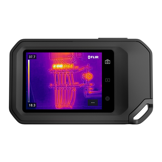
FLIR C 5 Series User Manual
Hide thumbs
Also See for C 5 Series:
- User manual (42 pages) ,
- User manual (25 pages) ,
- Quick start (2 pages)
Table of Contents
Advertisement
Advertisement
Table of Contents

Summary of Contents for FLIR C 5 Series
- Page 1 User manual FLIR Cx5...
-
Page 3: Table Of Contents
Installing the FLIR C5 camera........ -
Page 4: Notice To User
FLIR Cx5 case. Before operating the device, your must read, understand, and follow all instructions, warnings, and legal disclaimers. For information on the use and operation of the FLIR C5 camera, please refer to the FLIR C5 user manual. 1.2 Online documentation Our manuals are continuously updated and published online. -
Page 5: Disclaimers
2.3 Copyright © 2022 FLIR Systems, Inc. All rights reserved worldwide. No parts of the soft- ware including source code may be reproduced, transmitted, transcribed or translated into any language or computer language in any form or by any means, electronic, magnetic, optical, manual or otherwise, without the prior written per- mission of FLIR Systems. -
Page 6: Safety Information
Do not disassemble in the hazardous area. WARNING Only use the FLIR Cx5 with the FLIR C5 pocket thermal imaging camera. WARNING If there are any grounds to believe the unit is no longer safe to use, it must be removed from service and measures taken to prevent its further unintentional use. -
Page 7: Ex Compliance Marking
Standards ATEX EN IEC 60079-0:2018 EN IEC 60079-15:2019 EN 60079-31:2014 IECEx IEC 60079-0:2017 IEC 60079-15:2017 IEC 60079-31:2013 UKCA (Ex) EN IEC 60079-0:2018 EN IEC 60079-15:2019 EN 60079-31:2014 The FLIR Cx5 certifications are available online at http://support.flir.com/resources/cx. #T810609; r. AB/88437/88437; en-US... -
Page 8: Flir Cx5 Operations
The FLIR Cx5 case is designed to accommodate the standard USB-C charge/ download cable of the FLIR C5 camera. To access the USB-C port of the FLIR C5 camera, remove the USB plug lo- cated on the edge of the case. -
Page 9: Tripod Mount
4 FLIR Cx5 operations Figure 4.1 FLIR Cx5 with USB cable connected. 4.3 Tripod mount The FLIR Cx5 case incorporates a centralised, bottom mounted tripod boss with a standard UNC ¼″-20. Figure 4.2 FLIR Cx5 attached to tripod. #T810609; r. AB/88437/88437; en-US... -
Page 10: Routine Testing, Inspection, And Maintenance
5.1 Routine testing, inspection, and maintenance The FLIR Cx5 case relies upon its seals to prevent the entry of potentially explo- sive gas into the enclosure. It is important therefore that these seals are checked and where necessary replaced. -
Page 11: Opening And Installation
WARNING The FLIR Cx5 certification is void if the unit is tampered with or if the FLIR C5 is not correctly installed in the FLIR Cx5 case. WARNING Do not exert excessive pressure onto the window in the FLIR Cx5 case. - Page 12 6 Opening and installation Turn the FLIR Cx5 case over so that the lenses are facing upwards. Using the H2.0 hex screwdriver, remove the eleven (11) bolts securing the case halves as shown in Figure 6.2. Figure 6.2 FLIR Cx5 main retaining bolts.
-
Page 13: Installing The Flir C5 Camera
Once all fixing bolts are in place, complete the case closure by tightening the bolts in a diametrically opposed manner until finger tight. Turn the FLIR Cx5 case so that the lenses face down, and then complete the installation of the four (4) shock absorber bolts using the H1.5 hex screwdriver. - Page 14 Customer support http://support.flir.com Copyright © 2022, FLIR Systems, Inc. All rights reserved worldwide. Disclaimer Specifications subject to change without further notice. Models and accessories subject to regional market considerations. License procedures may apply. Products described herein may be subject to US Export Regulations. Please refer to exportquestions@flir.com with any questions.


Need help?
Do you have a question about the C 5 Series and is the answer not in the manual?
Questions and answers