Table of Contents
Advertisement
Advertisement
Table of Contents

Related Manuals for FLIR Cx series


Summary of Contents for FLIR Cx series
- Page 1 User’s manual FLIR Cx series...
- Page 3 User’s manual FLIR Cx series #T559918; r. AA/20829/20829; en-US...
-
Page 5: Table Of Contents
Table of contents Disclaimers ..................1 Legal disclaimer ................. 1 Usage statistics ................1 Changes to registry ..............1 U.S. Government Regulations............1 Copyright .................. 1 Quality assurance ............... 1 Patents ..................1 EULA Terms ................1 EULA Terms ................2 Safety information ................3 Notice to user ..................6 User-to-user forums .............. - Page 6 7.17.2 Procedure ..............20 Technical data ................... 21 Online field-of-view calculator ............21 Note about technical data ............21 FLIR C2 .................. 22 Mechanical drawings ................. 25 Cleaning the camera ................26 10.1 Camera housing, cables, and other items........26 10.1.1 Liquids.................
- Page 7 11.4.1 General................ 29 11.4.2 Figure................29 11.5 Draft ..................30 11.5.1 General................ 30 11.5.2 Figure................30 About FLIR Systems ................32 12.1 More than just an infrared camera ..........33 12.2 Sharing our knowledge .............. 33 12.3 Supporting our customers............34 12.4...
-
Page 9: Disclaimers
FLIR Systems will, at its option, repair or replace any such defective product ZL201230471744.3; ZL201230620731.8. free of charge if, upon inspection, it proves to be defective in material or work- manship and provided that it is returned to FLIR Systems within the said one- year period. 1.8 EULA Terms FLIR Systems has no other obligation or liability for defects than those set forth •... -
Page 10: Eula Terms
WITHOUT ANY WARRANTY; without even the implied warranty of MERCHANTABILITY or FITNESS FOR A PARTICULAR PURPOSE. See the Qt4 Core and Qt4 GUI, Copyright ©2013 Nokia Corporation and FLIR Sys- GNU Lesser General Public License, http://www.gnu.org/licenses/lgpl-2.1.html. tems AB. This Qt library is a free software; you can redistribute it and/or modify... -
Page 11: Safety Information
Applicability: Cameras with one or more batteries. Do not attach the batteries directly to a car’s cigarette lighter socket, unless FLIR Systems supplies a spe- cific adapter to connect the batteries to a cigarette lighter socket. Damage to the batteries can occur. - Page 12 Safety information CAUTION Applicability: Cameras with one or more batteries. Do not get water or salt water on the battery, or permit the battery to become wet. Damage to the batteries can occur. CAUTION Applicability: Cameras with one or more batteries. Do not make holes in the battery with objects.
- Page 13 Safety information CAUTION Applicability: Cameras with one or more batteries. Only use a specified battery charger when you charge the battery. Damage to the battery can occur if you do not do this. CAUTION Applicability: Cameras with one or more batteries. The temperature range through which you can charge the battery is ±0°C to +45°C (+32°F to +113°F), unless other information is specified in the user documentation or technical data.
-
Page 14: Notice To User
3.7 Important note about this manual FLIR Systems issues generic manuals that cover several cameras within a model line. This means that this manual may contain descriptions and explanations that do not apply to your particular camera model. -
Page 15: Customer Help
• The communication protocol, or method, between the camera and your device (for ex- ample, HDMI, Ethernet, USB, or FireWire) • Device type (PC/Mac/iPhone/iPad/Android device, etc.) • Version of any programs from FLIR Systems • Full name, publication number, and revision number of the manual 4.3 Downloads On the customer help site you can also download the following: •... - Page 16 Customer help • Technical datasheets. • Product catalogs. #T559918; r. AA/20829/20829; en-US...
-
Page 17: Quick Start Guide
Quick Start Guide 5.1 Procedure Follow this procedure: 1. Charge the battery for approximately 1.5 hours, using the FLIR power supply. 2. Push the On/off button to turn on the camera. 3. Aim the camera toward your target of interest. -
Page 18: Description
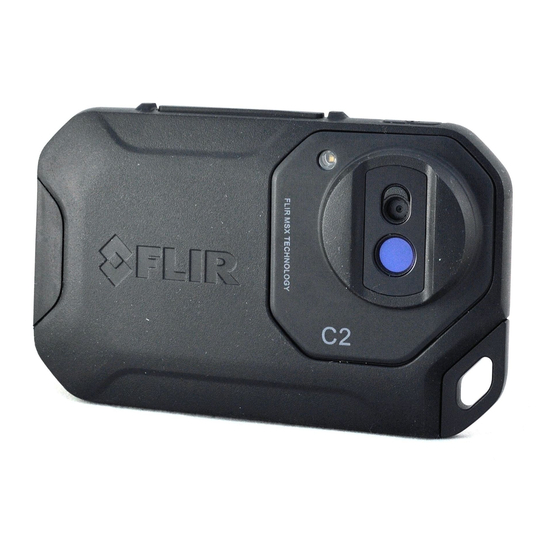
Description 6.1 View from the front 1. Camera lamp. 2. Digital camera lens. 3. Infrared lens. 4. Attachment point. 6.2 View from the rear 1. On/off button. 2. Save button. 3. Camera screen. #T559918; r. AA/20829/20829; en-US... -
Page 19: Connector
The purpose of this USB Micro-B connector is the following: • Charging the battery using the FLIR power supply. • Moving images from the camera to a computer for further analysis in FLIR Tools. Note Install FLIR Tools on your computer before you move the images. -
Page 20: Navigating The Menu System
Description Note The auto-orientation feature is enabled by a setting. Select Settings > Device settings > Auto orientation > On. 6.6 Navigating the menu system The camera has a touch screen. You can use your index finger or a stylus pen specially designed for capacitive touch usage to navigate the menu system. -
Page 21: Operation
Operation 7.1 Charging the battery Follow this procedure: 1. Connect the FLIR power supply to a wall outlet. 2. Connect the power supply cable to the USB connector on the camera. 7.2 Turning on and turning off the camera • Push the On/off button to turn on the camera. -
Page 22: Deleting An Image
Operation 5. Tap the camera screen. This displays a toolbar. • Select Full screen or Exit full screen to switch between the full screen and normal views. • Select Thumbnails to display the thumbnail overview. To scroll between the thumbnails, swipe up/down. To display an image, tap its thumbnail. •... -
Page 23: Measuring A Temperature Using A Spotmeter
Operation 7.7 Measuring a temperature using a spotmeter 7.7.1 General You can measure a temperature using a spotmeter. This will display the temperature at the position of the spotmeter on the screen. 7.7.1.1 Procedure Follow this procedure: 1. Tap the camera screen. This displays the main menu toolbar. 2. -
Page 24: Procedure
Operation • Thermal: The camera displays a fully infrared image. • Digital camera: The camera displays only the visual image captured by the digital camera. To display a good fusion image (Thermal MSX mode), the camera must make adjustments to compensate for the small difference in position between the digital camera lens and the infrared lens. -
Page 25: Changing The Temperature Scale Mode
Operation 4. If you have selected the Thermal MSX mode, also set the distance to the object by doing the following: • On the submenu toolbar, select Alignment distance . This displays a dialog box. • In the dialog box, select the distance to the object. 7.11 Changing the temperature scale mode 7.11.1 General The camera can operate in two different temperature scale modes:... -
Page 26: Procedure
Operation 7.12.2 Procedure Follow this procedure: 1. Tap the camera screen. This displays the main menu toolbar. 2. Select Settings . This displays a dialog box. 3. In the dialog box, select Measurement parameters. This displays a dialog box. 4. In the dialog box, select Emissivity. This displays a dialog box. 5. -
Page 27: Procedure
• Photo as separate JPEG: When this menu command is selected, the digital photograph from the visual camera is saved at its full field of view as a separate JPEG image. It may be necessary to activate this option if you are not using the FLIR Tools software. 7.16.1.3 Device settings •... -
Page 28: Procedure
1. Start FLIR Tools. 2. Start the camera. 3. Connect the camera to the computer using the USB cable. 4. On the Help menu in FLIR Tools, click Check for updates. 5. Follow the on-screen instructions. #T559918; r. AA/20829/20829; en-US... -
Page 29: Technical Data
FLIR Cx camera for field-of-view tables for all lens–camera combinations in this camera series. 8.2 Note about technical data FLIR Systems reserves the right to change specifications at any time without prior notice. Please check http://support.flir.com for latest changes. -
Page 30: Flir C2
Technical data 8.3 FLIR C2 P/N: 72001-0101 Rev.: 19634 Imaging and optical data IR resolution 80 × 60 pixels NETD 100 mK Field of view 45° × 34° Minimum focus distance • Thermal: 0.15 m (0.49 ft.) • MSX: 0.3 m (1 ft.) Focal length 1.54 mm (0.061 in.) - Page 31 Languages Lamp Output power 0.85 W 60° Field of view Service functions Camera software update Using FLIR Tools Storage of images Storage media Internal memory store at least 500 sets of images Image file format • Standard JPEG • 14-bit measurement data included...
- Page 32 Technical data Environmental data Humidity (operating and storage) IEC 60068-2-30/24 h 95% relative humidity +25°C to +40°C (+77°F to +104°F) / 2 cycles Relative humidity 95% relative humidity +25°C to +40°C (+77°F to +104°F) non condensing • WEEE 2012/19/EC • RoHs 2011/65/EC •...
-
Page 34: Cleaning The Camera
Cleaning the camera 10.1 Camera housing, cables, and other items 10.1.1 Liquids Use one of these liquids: • Warm water • A weak detergent solution 10.1.2 Equipment A soft cloth 10.1.3 Procedure Follow this procedure: 1. Soak the cloth in the liquid. 2. -
Page 35: Application Examples
Application examples 11.1 Moisture & water damage 11.1.1 General It is often possible to detect moisture and water damage in a house by using an infrared camera. This is partly because the damaged area has a different heat conduction property and partly because it has a different thermal capacity to store heat than the surrounding material. -
Page 36: Figure
Application examples 11.2.2 Figure The image below shows a connection of a cable to a socket where improper contact in the connection has resulted in local temperature increase. 11.3 Oxidized socket 11.3.1 General Depending on the type of socket and the environment in which the socket is installed, ox- ides may occur on the socket's contact surfaces. -
Page 37: Insulation Deficiencies
Application examples 11.4 Insulation deficiencies 11.4.1 General Insulation deficiencies may result from insulation losing volume over the course of time and thereby not entirely filling the cavity in a frame wall. An infrared camera allows you to see these insulation deficiencies because they either have a different heat conduction property than sections with correctly installed insulation, and/or show the area where air is penetrating the frame of the building. -
Page 38: Draft
Application examples 11.5 Draft 11.5.1 General Draft can be found under baseboards, around door and window casings, and above ceil- ing trim. This type of draft is often possible to see with an infrared camera, as a cooler air- stream cools down the surrounding surface. Note When you are investigating draft in a house, there should be sub-atmospheric pressure in the house. - Page 39 Application examples #T559918; r. AA/20829/20829; en-US...
-
Page 40: About Flir Systems
About FLIR Systems FLIR Systems was established in 1978 to pioneer the development of high-performance infrared imaging systems, and is the world leader in the design, manufacture, and market- ing of thermal imaging systems for a wide variety of commercial, industrial, and govern- ment applications. -
Page 41: More Than Just An Infrared Camera
10 L (2.6 US gallon) jar with liquid nitrogen. To the left of the oscilloscope the Polaroid attachment (6 kg/13 lb.) can be seen. RIGHT: FLIR One, which was launched in January 2014, is a slide-on attachment that gives iPhones thermal imaging capabilities. -
Page 42: Supporting Our Customers
12.3 Supporting our customers FLIR Systems operates a worldwide service network to keep your camera running at all times. If you discover a problem with your camera, local service centers have all the equip- ment and expertise to solve it within the shortest possible time. -
Page 43: Glossary
Glossary The amount of radiation absorbed by an object relative to the re- absorption (ab- sorption factor) ceived radiation. A number between 0 and 1. atmosphere The gases between the object being measured and the camera, nor- mally air. autoadjust A function making a camera perform an internal image correction. - Page 44 Glossary IFOV Instantaneous field of view: A measure of the geometrical resolution of an IR camera. image correc- A way of compensating for sensitivity differences in various parts of tion (internal or live images and also of stabilizing the camera. external) infrared Non-visible radiation, having a wavelength from about 2–13 μm.
- Page 45 Glossary relative Relative humidity represents the ratio between the current water va- humidity pour mass in the air and the maximum it may contain in saturation conditions. saturation The areas that contain temperatures outside the present level/span color settings are colored with the saturation colors. The saturation colors contain an ‘overflow’...
-
Page 46: Thermographic Measurement Techniques
Thermographic measurement techniques 14.1 Introduction An infrared camera measures and images the emitted infrared radiation from an object. The fact that radiation is a function of object surface temperature makes it possible for the camera to calculate and display this temperature. However, the radiation measured by the camera does not only depend on the temperature of the object but is also a function of the emissivity. - Page 47 Thermographic measurement techniques 14.2.1.1.1 Method 1: Direct method Follow this procedure: 1. Look for possible reflection sources, considering that the incident angle = reflection an- gle (a = b). Figure 14.1 1 = Reflection source 2. If the reflection source is a spot source, modify the source by obstructing it using a piece if cardboard.
- Page 48 Thermographic measurement techniques 3. Measure the radiation intensity (= apparent temperature) from the reflecting source us- ing the following settings: • Emissivity: 1.0 • D You can measure the radiation intensity using one of the following two methods: Figure 14.3 1 = Reflection source Note Using a thermocouple to measure reflected apparent temperature is not recommended for two important reasons:...
-
Page 49: Reflected Apparent Temperature
Thermographic measurement techniques 5. Measure the apparent temperature of the aluminum foil and write it down. Figure 14.4 Measuring the apparent temperature of the aluminum foil. 14.2.1.2 Step 2: Determining the emissivity Follow this procedure: 1. Select a place to put the sample. 2. -
Page 50: Distance
50%. 14.6 Other parameters In addition, some cameras and analysis programs from FLIR Systems allow you to com- pensate for the following parameters: • Atmospheric temperature – i.e. the temperature of the atmosphere between the camera and the target •... -
Page 51: History Of Infrared Technology
History of infrared technology Before the year 1800, the existence of the infrared portion of the electromagnetic spectrum wasn't even suspected. The original significance of the infrared spectrum, or simply ‘the in- frared’ as it is often called, as a form of heat radiation is perhaps less obvious today than it was at the time of its discovery by Herschel in 1800. - Page 52 History of infrared technology Moving the thermometer into the dark region beyond the red end of the spectrum, Her- schel confirmed that the heating continued to increase. The maximum point, when he found it, lay well beyond the red end – in what is known today as the ‘infrared wavelengths’. When Herschel revealed his discovery, he referred to this new portion of the electromag- netic spectrum as the ‘thermometrical spectrum’.
- Page 53 History of infrared technology Figure 15.4 Samuel P. Langley (1834–1906) The improvement of infrared-detector sensitivity progressed slowly. Another major break- through, made by Langley in 1880, was the invention of the bolometer. This consisted of a thin blackened strip of platinum connected in one arm of a Wheatstone bridge circuit upon which the infrared radiation was focused and to which a sensitive galvanometer re- sponded.
-
Page 54: Theory Of Thermography
Theory of thermography 16.1 Introduction The subjects of infrared radiation and the related technique of thermography are still new to many who will use an infrared camera. In this section the theory behind thermography will be given. 16.2 The electromagnetic spectrum The electromagnetic spectrum is divided arbitrarily into a number of wavelength regions, called bands, distinguished by the methods used to produce and detect the radiation. -
Page 55: Planck's Law
Such cavity radiators are commonly used as sources of radiation in temperature refer- ence standards in the laboratory for calibrating thermographic instruments, such as a FLIR Systems camera for example. If the temperature of blackbody radiation increases to more than 525°C (977°F), the source begins to be visible so that it appears to the eye no longer black. -
Page 56: Wien's Displacement Law
Theory of thermography where: Blackbody spectral radiant emittance at wavelength λ. λb Velocity of light = 3 × 10 Planck’s constant = 6.6 × 10 Joule sec. Boltzmann’s constant = 1.4 × 10 Joule/K. Absolute temperature (K) of a blackbody. λ... - Page 57 Theory of thermography This is Wien’s formula (after Wilhelm Wien, 1864–1928), which expresses mathematically the common observation that colors vary from red to orange or yellow as the temperature of a thermal radiator increases. The wavelength of the color is the same as the wavelength calculated for λ...
-
Page 58: Stefan-Boltzmann's Law
Theory of thermography 16.3.3 Stefan-Boltzmann's law By integrating Planck’s formula from λ = 0 to λ = ∞, we obtain the total radiant emittance ) of a blackbody: This is the Stefan-Boltzmann formula (after Josef Stefan, 1835–1893, and Ludwig Boltz- mann, 1844–1906), which states that the total emissive power of a blackbody is propor- tional to the fourth power of its absolute temperature. - Page 59 Theory of thermography Another factor, called the emissivity, is required to describe the fraction ε of the radiant emittance of a blackbody produced by an object at a specific temperature. Thus, we have the definition: The spectral emissivity ε = the ratio of the spectral radiant power from an object to that λ...
-
Page 60: Infrared Semi-Transparent Materials
Theory of thermography Figure 16.8 Spectral radiant emittance of three types of radiators. 1: Spectral radiant emittance; 2: Wave- length; 3: Blackbody; 4: Selective radiator; 5: Graybody. Figure 16.9 Spectral emissivity of three types of radiators. 1: Spectral emissivity; 2: Wavelength; 3: Black- body;... - Page 61 Theory of thermography When the plate becomes opaque this formula is reduced to the single formula: This last relation is a particularly convenient one, because it is often easier to measure re- flectance than to measure emissivity directly. #T559918; r. AA/20829/20829; en-US...
-
Page 62: The Measurement Formula
The measurement formula As already mentioned, when viewing an object, the camera receives radiation not only from the object itself. It also collects radiation from the surroundings reflected via the ob- ject surface. Both these radiation contributions become attenuated to some extent by the atmosphere in the measurement path. - Page 63 U according to the same equation, and get (Equation 3): Solve Equation 3 for U (Equation 4): This is the general measurement formula used in all the FLIR Systems thermographic equipment. The voltages of the formula are: Table 17.1 Voltages Calculated camera output voltage for a blackbody of temperature T i.e.
- Page 64 5 volts, the resulting curve would have been very much the same as our real curve extrapolated beyond 4.1 volts, provided the calibration algorithm is based on ra- diation physics, like the FLIR Systems algorithm. Of course there must be a limit to such extrapolations.
- Page 65 The measurement formula Figure 17.2 Relative magnitudes of radiation sources under varying measurement conditions (SW camera). 1: Object temperature; 2: Emittance; Obj: Object radiation; Refl: Reflected radiation; Atm: atmosphere radia- tion. Fixed parameters: τ = 0.88; T = 20°C (+68°F); T = 20°C (+68°F).
-
Page 66: Emissivity Tables
Emissivity tables This section presents a compilation of emissivity data from the infrared literature and measurements made by FLIR Systems. 18.1 References 1. Mikaél A. Bramson: Infrared Radiation, A Handbook for Applications, Plenum press, N. 2. William L. Wolfe, George J. Zissis: The Infrared Handbook, Office of Naval Research, Department of Navy, Washington, D.C. - Page 67 Emissivity tables Table 18.1 T: Total spectrum; SW: 2–5 µm; LW: 8–14 µm, LLW: 6.5–20 µm; 1: Material; 2: Specification; 3: Temperature in °C; 4: Spectrum; 5: Emissivity: 6:Reference (continued) Aluminum anodized, light 0.61 gray, dull Aluminum anodized, light 0.97 gray, dull Aluminum as received, plate...
- Page 68 Emissivity tables Table 18.1 T: Total spectrum; SW: 2–5 µm; LW: 8–14 µm, LLW: 6.5–20 µm; 1: Material; 2: Specification; 3: Temperature in °C; 4: Spectrum; 5: Emissivity: 6:Reference (continued) Brass dull, tarnished 20–350 0.22 Brass oxidized 0.61 Brass oxidized 0.04–0.09 Brass oxidized...
- Page 69 Emissivity tables Table 18.1 T: Total spectrum; SW: 2–5 µm; LW: 8–14 µm, LLW: 6.5–20 µm; 1: Material; 2: Specification; 3: Temperature in °C; 4: Spectrum; 5: Emissivity: 6:Reference (continued) Bronze polished Bronze porous, rough 50–150 0.55 Bronze powder 0.76–0.80 Carbon candle soot 0.95...
- Page 70 Emissivity tables Table 18.1 T: Total spectrum; SW: 2–5 µm; LW: 8–14 µm, LLW: 6.5–20 µm; 1: Material; 2: Specification; 3: Temperature in °C; 4: Spectrum; 5: Emissivity: 6:Reference (continued) Emery coarse 0.85 Enamel Enamel lacquer 0.85–0.95 Fiber board hard, untreated 0.85 0.75 Fiber board...
- Page 71 Emissivity tables Table 18.1 T: Total spectrum; SW: 2–5 µm; LW: 8–14 µm, LLW: 6.5–20 µm; 1: Material; 2: Specification; 3: Temperature in °C; 4: Spectrum; 5: Emissivity: 6:Reference (continued) Iron and steel oxidized strongly 0.88 Iron and steel oxidized strongly 0.98 Iron and steel polished...
- Page 72 Emissivity tables Table 18.1 T: Total spectrum; SW: 2–5 µm; LW: 8–14 µm, LLW: 6.5–20 µm; 1: Material; 2: Specification; 3: Temperature in °C; 4: Spectrum; 5: Emissivity: 6:Reference (continued) Lacquer 3 colors sprayed 0.50–0.53 on Aluminum Lacquer 3 colors sprayed 0.92–0.94 on Aluminum Lacquer...
- Page 73 Emissivity tables Table 18.1 T: Total spectrum; SW: 2–5 µm; LW: 8–14 µm, LLW: 6.5–20 µm; 1: Material; 2: Specification; 3: Temperature in °C; 4: Spectrum; 5: Emissivity: 6:Reference (continued) Nickel bright matte 0.041 Nickel commercially 0.045 pure, polished Nickel commercially 200–400 0.07–0.09...
- Page 74 Emissivity tables Table 18.1 T: Total spectrum; SW: 2–5 µm; LW: 8–14 µm, LLW: 6.5–20 µm; 1: Material; 2: Specification; 3: Temperature in °C; 4: Spectrum; 5: Emissivity: 6:Reference (continued) Paint oil, black flat 0.94 Paint oil, black gloss 0.92 Paint oil, gray flat 0.97...
- Page 75 Emissivity tables Table 18.1 T: Total spectrum; SW: 2–5 µm; LW: 8–14 µm, LLW: 6.5–20 µm; 1: Material; 2: Specification; 3: Temperature in °C; 4: Spectrum; 5: Emissivity: 6:Reference (continued) Platinum 0.05 Platinum 1000–1500 0.14–0.18 Platinum 1094 0.18 Platinum 0.016 Platinum 0.03 Platinum...
- Page 76 Emissivity tables Table 18.1 T: Total spectrum; SW: 2–5 µm; LW: 8–14 µm, LLW: 6.5–20 µm; 1: Material; 2: Specification; 3: Temperature in °C; 4: Spectrum; 5: Emissivity: 6:Reference (continued) sheet, untreated, 0.28 Stainless steel somewhat scratched Stainless steel type 18-8, buffed 0.16 Stainless steel type 18-8, oxi-...
- Page 77 Emissivity tables Table 18.1 T: Total spectrum; SW: 2–5 µm; LW: 8–14 µm, LLW: 6.5–20 µm; 1: Material; 2: Specification; 3: Temperature in °C; 4: Spectrum; 5: Emissivity: 6:Reference (continued) Wood 0.962 Wood ground 0.5–0.7 Wood pine, 4 different 0.67–0.75 samples Wood pine, 4 different...
- Page 80 Disclaimer Specifications subject to change without further notice. Models and accessories subject to regional market considerations. License procedures may apply. Products described herein may be subject to US Export Regulations. Please refer to exportquestions@flir.com with any questions. Publ. No.: T559918...
Need help?
Do you have a question about the Cx series and is the answer not in the manual?
Questions and answers