Table of Contents
Advertisement
Quick Links
Advertisement
Table of Contents

Related Manuals for RADWAG SM-UYA 4Y


Summary of Contents for RADWAG SM-UYA 4Y
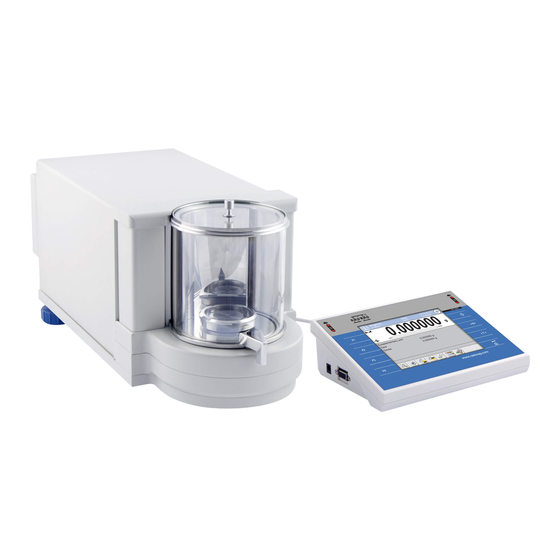
- Page 1 Susceptometer SM-UYA 4Y SM-MYA 4Y USER MANUAL IMMU-99-01-08-18-EN www.radwag.com...
- Page 2 Congratulations and thank you for selecting RADWAG product. You have purchased a device that has been designed and manufactured to give you years of service. Please read this User Manual carefully, this shall guarantee reliable operation. AUGUST 2018 "The drawings, photos and graphics - 2 - used are for illustrative purposes only."...
-
Page 3: Table Of Contents
CONTENTS 1. GENERAL INFORMATION ..............6 1.1. Dimensions ................... 6 1.2. Connectors Arrangement ................. 6 1.3. Intended Use ..................7 1.4. Precautions ................... 7 1.5. Warranty Conditions ................8 1.6. Supervision Over Metrological Parameters ..........8 1.7. User Manual Significance ................. 8 1.8. - Page 4 13.1. Password Settings ................27 13.2. Operator Accounts Settings ..............28 13.3. Permissions Management ..............29 14. PROFILES ..................31 14.1. Creating a Profile ................. 31 14.2. Profile Structure ................... 32 14.2.1. Settings ....................33 14.2.2. Working Modes ..................33 14.2.3.
- Page 5 19.4. TCP Settings ..................67 20. PERIPHERALS ................. 67 20.1. Computer .................... 67 20.2. Printer ....................68 20.3. Barcode Scanner .................. 69 20.3.1. Barcode Scanner Port ................70 20.3.2. Prefix/Suffix..................70 20.3.3. Field Selection ..................70 20.3.4. Test ....................72 20.4.
-
Page 6: General Information
1. GENERAL INFORMATION 1.1. Dimensions Indicator 1.2. Connectors Arrangement Connectors arrangement: 1 – Ethernet RJ45 connector 4 – I/O, RS232 (COM2) connector 2 – RS232 (COM1) connector - 6 -... -
Page 7: Intended Use
3 – USB connector balance – computer cable (RS232) balance – printer cable (EPSON) I/O cable Caution: "Ethernet – weighing device” cable is a standard network cable terminated with RJ45 connectors on both ends. 1.3. Intended Use SM susceptometer enables carrying out measurements of magnetic susceptibility and magnetization of mass standards and weights of class E1 and lower in accordance with OIML R111. -
Page 8: Warranty Conditions
1.5. Warranty Conditions A. RADWAG feels obliged to repair or exchange all elements that appear to be faulty by production or by construction. B. Defining defects of unclear origin and means of their elimination can only be realized with assistance of the manufacturer and user representatives. -
Page 9: Transport And Storage
2. TRANSPORT AND STORAGE 2.1. Delivery Check Upon delivery it is necessary to check the package and the device, make sure that your package bears no signs of damage. Otherwise contact the manufacturer's representative. 2.2. Packaging Keep all package elements should your device be transported in the future. Remember that only original packaging can be used for shipping purposes. -
Page 10: Unpacking
3.2. Unpacking Cut the adhesive tape. Take the device components and the wooden box with the device out of the packaging. Unscrew 3 screws fixing the device to the box and take them out. Screw 2 feet and base bracket into device's base. - 10 -... -
Page 11: Standard Delivery Components List
3.3. Standard Delivery Components List • Balance • Device feet • Base support • Mass standard support • Mass standard support plate • Draft shield • Magnet • Magnet support • Weighing pan • Anti-draft chamber glass lid • Power supply •... - Page 12 - 12 -...
-
Page 13: Connecting The Device To The Mains
3.5. Connecting the Device to the Mains The weighing device can be connected to the mains only with a power supply that comes standard with a particular model. Nominal voltage of the power supply (specified on the power supply data plate) has to be compatible with the mains nominal voltage. Plug the balance to the mains –... -
Page 14: Maintenance
4. MAINTENANCE CAUTION: Cleaning the weighing pan or the magnet support while still installed may cause damage of the measuring system. 1. Uninstall the weighing pan and other detachable components depending on balance type (refer to section: UNPACKING AND INSTALLATION). Be careful while detaching the components so as not to cause any damages to the mechanism. -
Page 15: Start-Up
• Press key located on the top of the operation panel. Within a few seconds the OS Windows and RADWAG software start loading, it is signalled by flickering ON/LOAD red diode. • Upon completed start-up the home screen is displayed automatically. -
Page 16: Keys
6. KEYS Description Press to switch the balance ON/OFF Press to zero the balance Press to tare the balance Press to send measurement to a printer or a computer Press to enter the menu Press to select working mode; programmable key Press to select profile;... -
Page 17: Program
7. PROGRAM Program menu is divided into function groups. Function group is a group of interrelated parameters. For detailed description of each menu group read later sections of this user manual. Menu - Function Groups: To access the menu press SETUP function key or button located in the bottom part of the display. -
Page 18: Home Screen
8. HOME SCREEN The home screen features 4 sections: • Top section displaying data on active working mode, logged in user, date, time, computer connection status and level status. • Section presenting the weighing result and a current measuring unit. •... -
Page 19: Log In Operation
9. LOG IN OPERATION In order to access operator-related parameters and in order to edit databases, you need to log in as an operator with <Administrator> permissions level. First log in operation: • Go to home screen, press <Log in> button, wait for the operators database and < Admin>... -
Page 20: Operating The Menu
10. OPERATING THE MENU Operation of device program menu is intuitive. The touch panel makes the software operation easy. By pressing an on-screen button or any field, you activate respective function/operation. 10.1. Navigation Press to enter the main menu. Press to scroll the menu 'up' Press to scroll the menu 'down' Press to scroll the menu 'up-down' fast Press to confirm modification... -
Page 21: Adjustment
11. ADJUSTMENT The module features automatic internal adjustment system which ensures correct measurement accuracy. <ADJUSTMENT> menu contains functions controlling operation of module adjustment process. 11.1. Internal Adjustment Internal adjustment is carried out by means of an internal adjustment weight. <Internal adjustment>... -
Page 22: User Adjustment
11.3. User Adjustment User adjustment can be carried out using any adjustment weight mass of which ranges between 0.15 Max and Max. User adjustment and external adjustment procedures are likewise with one exception, before user adjustment start, an edit box for entering mass of the used adjustment weight is opened. - Page 23 Enter operator menu, select <Adjustment> submenu and find <Scheduled adjustments> parameter. Enter <Scheduled adjustments> parameter, wait for ‘Scheduled adjustments’ window to open, add adjustment procedures. Remember, only Administrator can add new entries. In order to add a new position, press button, wait for a window with data on scheduled adjustment to open.
-
Page 24: Report Printout
For automatic adjustment option, enter data on the adjustment and its schedule. For external adjustment option, enter data on the adjustment, mass standard used for the adjustment performance and its schedule. When all necessary data has been introduced, return to the previous window. The window features newly added entry. -
Page 25: Adjustment History
nominal mass current mass difference temperature empty line dashes signature non-standard printout 11.10. Adjustment History Adjustment history contains data on all carried out adjustment processes. The record is carried out automatically. Each record on adjustment comprises basic data on completed process. -
Page 26: Operators
12. OPERATORS Operators database features list of users permissioned to operate the weighing device. The following data can be defined for each balance operator: Name Code Password Name and surname Permissions Account active Language ... -
Page 27: Administrator Panel
13. ADMINISTRATOR PANEL Administrator panel enables to determine activities of an operator with determined permissions, password strength and permissions for an unlogged operator. CAUTION: Only operator with <Administrator> permissions can modify this menu. 13.1. Password Settings Menu enables to determine password strength. Minimum password characters Determining minimum quantity of characters in quantity... -
Page 28: Operator Accounts Settings
13.2. Operator Accounts Settings Permissions of an unlogged operator Administrator can assign an unlogged weighing device operator (so called anonymous operator) with permissions level. Procedure: • Enter < Permissions> menu. • Select <Anonymous operator> parameter. • Set appropriate permissions for the anonymous user. •... -
Page 29: Permissions Management
13.3. Permissions Management Databases Default balance settings enable operator who is logged as Administrator to modify databases. The software allows to change permissions. Procedure: • Enter < Administrator panel> submenu, select <Databases> option, next set respective permissions. • Set one of four options: Guest, Operator, Advanced operator, Administrator. CAUTION: When <Guest>... - Page 30 Printouts Default balance settings enable operator who is logged as Administrator to edit printouts but the software allows to change permissions, and as a result authorize other operators to access < Printouts> parameter. Procedure: • Enter < Permissions> menu. • Select < Printouts>...
-
Page 31: Profiles
14. PROFILES A Profile is a data pack that determines: function operation, e.g. parts counting, percent weighing, etc. data to be displayed during operation, function keys to be active, measuring units to be accessible criteria determining speed of operation and measurement stability, Balance software allows you to create numerous profiles, this enables: ... -
Page 32: Profile Structure
• A new <Copy name> profile is created, new profile settings and base profile settings are identical. • Modify necessary data: (name, etc.). Adding a new profile Procedure: • Enter the main menu, to do it press Setup key. • Enter <Profiles>... -
Page 33: Settings
14.2.1. Settings Name Upon entering this parameter, a message box with an on-screen keyboard is displayed. Enter the name of a profile and press button to confirm. The name is assigned to the profile. Default working mode Upon entering this parameter you can select a specific working mode that is to be set as default. -
Page 34: Units
There are three different settings for value release parameter: • fast, fast and reliable, reliable. CAUTION: Both parameters, filter and value release, determine how long it takes to obtain stable result. Autozero Function The function has been designed to enable automatic control and correction of zero indication. -
Page 35: Working Modes - General Information
The obtained result is processed and displayed on the balance screen in a digital format. MAGNETISM RADWAG-manufactured susceptometer enables carrying out measurement of magnetic susceptibility and magnetization of weights of class E1 and lower in accordance with OIML R111. -
Page 36: Working Mode Parameters
15.2. Working Mode Parameters Each working mode has programmable parameters determining its functioning. To access particular working mode parameters: 1. Press grey workspace area. 2. The following menu is displayed: • <Settings> - additional options. • <Keys> - defining quick access buttons . •... -
Page 37: Information
4. Hand motion to the right over both sensors (move your hand over left sensor first, right next) <Proximity sensor: gesture to the right>. Caution: Using GESTURE TO THE LEFT or GESTURE TO THE RIGHT, it is necessary to remember that <Proximity sensors delay>... -
Page 38: Profiles
− − Gross − Product Packaging − Current result − − Packaging Universal variable 1 … 5 − Additional unit − − Universal variable 1 … 5 Dashes − Mass − − Empty line Empty line − Non-standard printout − −... -
Page 39: Weighing
16. WEIGHING Load the weighing pan. Wait for a stable indication (display of stability marker, ) and read the measurement result. Record/printout of the measurement result is available on pressing <PRINT> key: • for non-verified balances – stable and unstable measurement results are saved or printed (regardless of stability marker absence). -
Page 40: Level Status
16.3. Level Status The balance is equipped with an AutoLEVEL System which enables monitoring of the balance level. Level monitoring is performed uninterruptedly in the course of balance operation. Level status is signalled with a respective pictogram, displayed in the upper right corner of the work panel. -
Page 41: Use Of Air Buoyancy Compensation Factor
CAUTION: It is impossible to tare negative values. When you try to tare negative values, the weighing instrument responds with an error message: Err3. In such case, zero the indication and repeat taring procedure. Entering tare value manually Procedure: • Press quick access button. The button is available regardless of the working mode you operate •... - Page 42 Error value in relation to density of weighed sample The graph presents correction values for versus the density of weighed load, assumption that air density is constant and equals 1.2 kg/m is taken. 2. testing sample mass change within a few hours long period of time for a case when the sample mass is relatively constant (minor changes).
- Page 43 • 2. Select <Settings> parameter. • Select < Air buoyancy compensation> parameter. Parameter values: - Air buoyancy compensation – YES/NO. - Sample density (enter value of weighed sample density). If you use products from databases, then on product selection its density value is automatically uploaded. - Air density –...
-
Page 44: Additional Parameters For A Weighing Process
16.7. Additional Parameters for a Weighing Process Modification of weighing functions enables programming balance operation. Procedure: • Press grey workspace area. • The following submenus are displayed: Settings, Buttons, Information, Printouts, Profile. • Enter particular submenu and select the component that is to be modified <Settings>... - Page 45 Never – printout disabled. First stable – first stable measurement is recorded. Each stable – all stable measurements are registered. Each – printout of all measurements (stable and unstable), for verified balance only stable measurements are printed out (as in <Each stable> setting). •...
-
Page 46: Minimum Sample Weight
Should you use the minimum sample weight function, and need data on minimal sample weight to be entered to balance menu, please contact the local representative of “RADWAG” company. Using reference weights, the authorized RADWAG employee determines minimum sample weight for specified tare containers. - Page 47 Weighing with use of <MINIMUM SAMPLE WEIGHT> function If in the course of weighing you want to find out whether a particular measurement value is higher than the MSW value, specified for a given weighing range, then <Minimum sample weight> function must be on. To turn the function on go to weighing mode settings. Procedure: 1.
-
Page 48: Cooperation With Titrators
The validity period of the minimum sample weight has expired. The minimum sample weight settings need to be modified. The minimum sample weight settings can be modified by an authorized RADWAG personnel exclusively. CAUTION:... -
Page 49: Ambient Conditions - Vibrations
(rms value) and bandwidth. Such analysis is performed on each 4Y series balance in a real time. In case of the module that is in-built into balances manufactured by RADWAG, the filters analyse those frequencies to which the weighing devices are sensitive. In case of balances, effective value (rms value) measured from 3 axes and for a particular time interval is given, such value provides information on amplitude and history of disturbances. - Page 50 2 seconds. This value is refreshed every 2 seconds. If the screen displays 100% value, this means that vibrations have reached threshold set by RADWAG. Vibrations are recorded in the database, this allows to analyse history of ambient conditions quality.
- Page 51 Effective value of vibrations registered by the balance over a declared time interval is saved (from the moment of the last record) – Setup/Ambient conditions/Ambient conditions recording interval. By default the interval is set to 10 min, this value may range between 1 min - 60 min. Record analysis allows the user to select optimal time of the day for the measurement performance, i.e.
-
Page 52: Magnetism
17. MAGNETISM CAUTION: Prior to measurement, carry out internal adjustment. Prior to measurement, set mass standard support plate depending on the test weight, so that the distance between the test weight and the magnet is compliant with the requirements. For mass standards of class E1 - 20 mm distance (marking Z1 on the plate). For mass standards of class E2- 27 mm distance (marking Z2 on the plate). - Page 53 Press button. A message to set the magnet to position 1 is displayed. Press button to confirm. The indication is automatically zeroed and the first step of the procedure is started. A message to load the test weight onto the spot marked on the bracket plate is displayed. Wait for a stable indication and press button to confirm.
- Page 54 Upon the last measurement confirmation, respective calculations are automatically carried out. The results are displayed on the grey workspace and saved to <Susceptibility: reports> entry. If report printout option is selected in the settings, the report is automatically printed. Prior to next measurement press button to confirm.
-
Page 55: Databases
18. DATABASES The module features the following databases < >: WEIGHING RECORDS CUSTOMERS SUSCEPTIBILITY: REPORTS MINIMUM SAMPLE AMBIENT CONDITIONS WAREHOUSES WEIGHT PRINTOUTS UNIVERSAL MANAGE THE VARIABLES DATABASE 18.1. Database Connected Operations Databases can be operated only by an authorized personnel. Procedure: •... -
Page 56: Weighing Records
• EXPORT - select to export data from selected database to a USB flash drive. Plug the USB flash drive to a USB port, upon its detection the software automatically starts a copying process. Upon completion of the copying process a window with both, a file name to which data has been saved and message: <Completed>... -
Page 57: Customers
6. Product name. 7. Operator. 8. Customer, customer name. 9. Working mode name. 10. Warehouse, source warehouse name. 11. Packaging, name of tare applied during product weighing. 12. Result control, information regarding range within which the weighed product is placed: MIN –... -
Page 58: Minimum Sample Weight
18.5. Minimum sample weight Minimum sample weight database contains data concerning declared methods and minimum sample weights. Caution: Only authorized RADWAG personnel can add new minimum sample weight records or make changes in those stored in the database. Procedure: •... -
Page 59: Ambient Conditions
values when weighing is carried out using a tare container of mass ranging from 0.0001 g to 10.0000 g inclusive (<TARE> button used). 50.0000 g 2.5000 g Minimum sample weight refers to all net weight values when weighing is carried out using a tare container of mass ranging from 10.0001 g to 50.0000 g inclusive (<TARE>... -
Page 60: Warehouses
Caution: It is possible to use ‘search report’ option. 18.7. Warehouses Depending on the organization of work, the warehouses database contains list of places used for picking up a sample for weighing or list of places to which a weighed sample was delivered. - Page 61 1 – zoom the edit box (7), recommended while using an external computer keyboard connected to module’s USB port, 2 – cancel 3 – confirm 4 – download a printout template from a file 5 – list of variables 6 – delete all printout content 7 –...
-
Page 62: Universal Variables
− Press [4] < Download a printout from a file> button, − Module's display shows data stored on the USB flash drive connected to the USB port. − Select a file with printout template and press its name. − The printout template is automatically copied to an editing field. 18.9. - Page 63 <Data selection> parameter allows you to specify which data related to measurement is to be exported. • Set respective data and press <Export weighing records database to a file> entry, weighing database is automatically exported. • Upon export completion, message <Completed> along with information on number of exported data and with file name (with *.txt extension) is displayed.
-
Page 64: Delete Databases
18.10.2. Delete Databases Function allowing to delete data of selected database. Upon function activation, window with databases list is displayed, select database, delete respective data. Upon confirmation, data is deleted and the following message is displayed: Upon confirmation the software returns to a previous window; you may continue weighing or proceed to other operations. -
Page 65: Communication
19. COMMUNICATION Communication menu is located in <Parameters> menu. To access Communication menu press Setup key or <Setup > quick access button. Communication between the balance and the peripheral devices is established via the following ports: − COM 1 (RS232), −... - Page 66 Procedure: − Select < Wifi> communication interface. Set the following parameters: • DHCP: Yes – No • IP Address: 10.10.9.155 • Subnet mask: 255.255.255.0 • Default gate: 10.10.8.244 CAUTION: Above settings are for information purpose only. Set the transmission parameters in accordance with your local network.
-
Page 67: Tcp Settings
19.4. TCP Settings TCP (Transmission Control Protocol) operating in customer-server mode enables communication of two computers. You can establish connection on port specified by server. Procedure: − Enter < Communication> parameter. − Select < Tcp / Port>; a <Port> window with an on-screen keyboard is opened. −... -
Page 68: Printer
20.2. Printer <Printer> submenu allows you to: − set port for establishing communication with printer, − define printer's code page (by default: 1250), − define control codes for PCL printer or EPSON receipt printer. Caution: Codes must be entered in a hexadecimal form! −... -
Page 69: Barcode Scanner
If there are any unexpected signs on the printout in the place of the last digit (for verified balances), then <CONTROL CODES> parameter must incorporate, apart from the code page, code of the UK signs chart: 1B5203. In such a case the <CONTROL CODES> parameter setting has to be as follows: control codes –... -
Page 70: Barcode Scanner Port
< Suffix> to synchronize mass comparator’s software with barcode scanner. CAUTION: In RADWAG-adopted standard, the prefix is 01 sign (byte) hexadecimal format, the suffix is 0D sign (byte) hexadecimal format. For detailed description of 'module' - 'barcode scanner' communication read APPENDIX E of this user manual. - Page 71 Product Series Operator Universal variable 1; Customer Universal variable 2; Packaging Universal variable 3; Warehouse Universal variable 4; Formulation Universal variable 5; Pipette • Select one item from the list. The following parameters may be edited: Filtering Declaring search criteria (see table below) Parameter allowing you to set the first significant Offset code's character.
-
Page 72: Test
Series None, Name, Code, Universal variables None, Active 20.3.4. Test < Test> parameter allowing you to verify if operation of a barcode scanner connected to a balance is correct. Procedure: • Enter < Barcode scanner> submenu, • Select < Test> parameter; <Test> edit box is displayed, it features ASCII and HEX fields. -
Page 73: Additional Display
• Press button to confirm. CAUTION: The balance cooperates with RADWAG WD5/3Y additional display. In order to ensure correct cooperation between the balance and the additional display, set {140} variable for < Project> parameter, next set 38400 bits/s baud rate for a port to which the additional display is connected. -
Page 74: Inputs/Outputs
21. INPUTS/OUTPUTS Application of inputs: The set of inputs is used to control module’s operation. The following functions or keys can be assigned to each of 4 inputs: o Checkweighing thresholds o Right door o Target value o Parameters o Profile o Statistics o Adjustment o Add to statistics... -
Page 75: Miscellaneous Parameters
The following data can be assigned to each of 4 outputs: Option Balance status switching output logic. None ------- Stable Each stable measurement switches the logic state. MIN stable Stable measurement below [MIN] threshold switches the logic state. MIN unstable Unstable measurement below [MIN] threshold switches the logic state. - Page 76 Pictog Name Value Description Parameter value: name of time (UTC+01:00) zone/country, Sarajevo, Time zone which informs of summer/winter time Skopje, change. The information comes from Warsaw, Zagreb Microsoft website. Function enables or disables automatic Automatically clock adjustment. adjust clock for Upon parameter change restart the daylight saving balance.
-
Page 77: Beep" Sound
22.3. „Beep” Sound Procedure: Enter < Misc.> submenu, select < Beep> parameter and set appropriate value: None - Beep sound disabled for keys/buttons and proximity sensors Keys/Buttons - Beep sound enabled for keys/buttons Sensors - Beep sound enabled for proximity sensors - Beep sound enabled for keys/buttons and proximity sensors 22.4. -
Page 78: Vibrations Detection
22.8. Vibrations Detection The program detects incorrect loading of the weighing pan with the sample, which can lead to increased indication errors. Function activation is signalled by a respective pictogram displayed in weighing result window. If incorrect loading of the weighing pan with the sample is detected, the pictogram turns to . -
Page 79: Proximity Sensors Timeout
Procedure: • Enter < Misc.> submenu. • Select <Proximity sensors sensitivity> parameter, an edit box is displayed. • Select one of available options. The selection causes immediate returning to the menu window. 22.11. Proximity Sensors Timeout Parameter for setting timeout of proximity sensors expressed in [ms]. Default value: <0>. - Page 80 shortest measurement time with acceptable value of repeatability; test results are stored in balance memory until it is turned off, test results printout, direct and fast selection of optimal parameters. Upon completed autotest, a summary with results is displayed. Information regarding filters settings is provided automatically via display of respective pictograms: - settings providing the fastest measurement (the shortest measurement time).
- Page 81 Report example: -------- Autotest Filter: Report -------- Balance type XA 4Y Balance S/N 442566 Operator Hubert Software ver. NL1.6.5 S Date 2015.05.07 Time 09:34:48 ---------------------------------------- Reading unit 0.0001/0.0001 g Internal weight mass 148.9390 g Temperature: Start 25.26 °C Temperature: Stop 25.66 °C ---------------------------------------- Filter Very fast Value release Fast...
- Page 82 AUTOTEST GLP The test controls repeatability of loading the internal weight and determining error of indication with reference to module’s maximum capacity. Procedure: • Two times loading of the internal weight, followed by 10 times loading of the internal weight. •...
-
Page 83: Start-Up Logo
(option enabled only for authorized mass comparator operators) The parameter enables you to generate a special type of a file that is automatically saved to a USB flash drive, plugged to USB port. The file helps RADWAG service to diagnose cause of problems occurring during balance operation. -
Page 84: About
24. ABOUT 'About' menu provides information on balance and balance program. Most of parameters in this menu are for the information purpose only. <Ambient conditions> parameter enables preview of present ambient conditions: temperature, humidity, pressure (if balance features ambient conditions sensors). -
Page 85: Communication Protocol
26. COMMUNICATION PROTOCOL General Information A. A character based communication protocol (balance-indicator) is designed for establishing communication between a RADWAG balance and a peripheral device via RS-232C interface. B. The protocol consists of commands sent from a peripheral device to the weighing instrument and responses from the weighing instrument. - Page 86 Send stable measurement result in current measuring unit Immediately send measurement result in current measuring unit Switch on continuous transmission in basic measuring unit Switch off continuous transmission in basic measuring unit Switch on continuous transmission in current measuring unit Switch off continuous transmission in current measuring unit Set min checkweighing threshold Set max checkweighing threshold...
-
Page 87: Response Format
Give current value release setting Set last digit Give accessible units Set unit Give current unit Compatibility with PUE 7.1, PUE 10 indicators CAUTION: Each command must end with CR LF characters. 26.2. Response Format On receipt of a command, the indicator responds as follows: XX_A CR LF command understood and in progress XX_D CR LF... - Page 88 Taring Format: T CR LF Response options: T_A CR LF - command understood and in progress T_D CR LF - command carried out T_A CR LF - command understood and in progress T_v CR LF - command understood but taring range is exceeded T_A CR LF - command understood and in progress T_E CR LF...
- Page 89 S_A CR LF - command understood and in progress - command carried out, immediate response: S _ _ _ _ - _ _ _ _ _ _ 8 . 5 _ g _ _ CR LF mass value in basic measuring unit where: _ - space Immediately send measurement result in basic measuring unit Format: SI CR LF...
- Page 90 7-15 stability space character mass space unit CR LF marker Example: S U I CR LF - command sent from a computer - command carried out, immediate response: S U I ? _ - _ _ _ 5 8 . 2 3 7 _ k g _ CR LF mass value in basic measuring unit where: _ - space Switch on continuous transmission in basic measuring unit...
- Page 91 DH_OK CR LF - command carried out ES CR LF - command not recognised (mass format incorrect) Set max checkweighing threshold Format: UH_XXXXX CR LF, where: _ - space, XXXXX - mass format Response options: UH_OK CR LF - command carried out ES CR LF - command not recognised (mass format incorrect) Give value of min checkweighing threshold...
- Page 92 than PERCENT WEIGHING) ES CR LF - command not recognised (mass format incorrect) Value release Format: SS CR LF Response options: SS_OK CR LF - command understood and in progress Command’s function is similar to function of PRINT key located on the instrument panel. Internal adjustment Format: IC CR LF Response options:...
- Page 93 K1_I CR LF - command understood but not accessible at this moment K1_OK CR LF - command carried out Command locks the balance keypad (proximity sensors, touch screen) until the moment of turning the balance off or until sending K0 command. Unlock balance keypad Format: K0 CR LF Response options:...
- Page 94 Example: command: OMS_1<CR><LF> - set WEIGHING mode - set WEIGHING Response: OMS_OK<CR><LF> Give current working mode Command overview: Command returns accessible working modes. Format: OMG<CR><LF> Response options: OMG_n_OK <CR><LF> - command carried out, response: current working mode OMG_I <CR><LF> - command understood but not accessible at this moment n - decimal value determining working mode number.
- Page 95 command: US_mg<CR><LF> - set „mg” unit Response: US_mg_OK<CR><LF> - „mg” set as a current unit Give current unit Command overview: Command returns current unit. Format: UG<CR><LF> Response options: UG_x_OK<CR><LF> - command carried out, returns accessible units UG_I <CR><LF> - command understood but not accessible at this moment x - parameter, units symbols Example: command:...
- Page 96 command: BN <CR><LF> - return balance type Response: BN_A_”AS” - balance type XA 4Y Give max capacity Format: FS <CR><LF> Response options: FS_A_”x” <CR><LF> - command understood, response: module max capacity FS_I <CR><LF> - command understood but not accessible at this moment x - Max value of reading units (in between inverted commas) Example: command:...
- Page 97 n - parameter, decimal value determining ambient conditions state n → 0 – unstable ambient conditions 1 – stable ambient conditions CAUTION: Command changes settings for a current working mode. Example: command: EV_1<CR><LF> - set value ‘stable’ for ambient conditions option Response: EV_OK<CR><LF>...
- Page 98 Response options: FIG_x_OK<CR><LF> - command carried out, response: currently set filter FIG_I <CR><LF> - command understood but not accessible at this moment x - parameter, symbol of currently set filter Example: command: FIG<CR><LF> - give current filter Response: FIG_2_OK<CR><LF> - currently set filter: average Set value release Format: ARS_n <CR><LF>...
- Page 99 - error in-course of command execution, no parameter or incorrect LDS_E <CR><LF> format LDS_I <CR><LF> - command understood but not accessible at this moment n - parameter, decimal value determining last digit settings n → 1 – always 2 – never 3 –...
- Page 100 Give accessible units Command overview: Command returns units available for a particular device and for a current working mode. Format: UI <CR><LF> Response options: UI_”x , … x ”_OK<CR><LF> - command carried out, returns accessible units UI_I <CR><LF> - command understood but not accessible at this moment X - unit symbols, separated by means of commas x →...
- Page 101 Compatibility with PUE 7.1, PUE 10 indicators Format: NT CR LF Response options: ES CR LF - command not recognised (mass format incorrect) - command carried out, immediate response: mass value in basic measuring MASS FRAME unit Response format: - command Stability - [space] if stable, [?] if unstable marker...
-
Page 102: Manual Printout / Automatic Printout
26.3. Manual Printout / Automatic Printout It is possible to generate printouts either manually or automatically. • Manual printout: upon indication stabilization press key. • Automatic printout is generated automatically in accordance with the parameters set for automatic printout (read section: 16.7). The content of printout depends on settings of <Standard printout>... -
Page 103: Error Messages
28. ERROR MESSAGES -no level- Balance not levelled -Err 100- Weighing module restart In process In-course process resulting in unstable measurement (automatic feeder – pills feeding process or comparator – load change process) - 103 -... -
Page 104: Additional Equipment
29. ADDITIONAL EQUIPMENT Type Name P0151 RS232 cable for EPSON printer EPSON Dot matrix printer PCL printer WD- xx Additional display in plastic housing CK-01 Transponder card scanner LS2208 Barcode scanner AP2-1 Current loop unit Anti-vibration bench for XA laboratory balances PC keyboard. - Page 105 {27} Value {28} Level status {30} Gross value {31} Weighing platform no. {32} Serial number {33} Reading unit {34} Range {35} Parts counting: Reference sample mass {36} Percent weighing: Reference mass {38} Universal variable: Name {39} Universal variable: Value {43} Net weight in a supplementary unit {44} Additional unit...
-
Page 106: Variables Formatting
Gross weight value in current unit {147} Tare in current unit {150} Epson printer: Paper crop {151} PCL printer: Form feed {155} Cooperation with RADWAG CONNECT {210} Adjustment history: Adjustment type {211} Adjustment history: Nominal mass {212} Adjustment history: Current mass {213}... - Page 107 Special formatting characters: Character Description Example Sign separating variable from {7,10} - Net weight in adjustment unit with constant format item. length of 10 characters, with right justification Minus sign or left justification {7,-10} - Net mass in adjustment unit with constant length of 10 characters, with left justification {7:0.000} - Net mass in adjustment unit always with Sign proceeding formatting or...
-
Page 108: Appendix B - Programmable Buttons List
31. APPENDIX B – Programmable Buttons List Pictogram Name Pictogram Name Profile selection Right door opening/closing Adjustment Open / close door Zeroing Parameters Taring Products Tare setting Warehouses Disable tare Customers Enable tare Help Packaging selection Footer printout Print Units Header printout Edit universal variable 1 Edit universal variable 2... -
Page 109: Appendix E - Communication With Barcode Scanner
5. A special protocol is required in order the code be received by RADWAG equipment. It is required to program an appropriate prefix and suffix. In RADWAG-adopted standard, the prefix is 01 sign (byte) hexadecimal format, the suffix is 0D sign (byte) hexadecimal format. - Page 110 Report printout No / Yes Displays a report on Adjustment history completed external adjustments Databases − Weighing records − Customers − Susceptibility: reports − Ambient conditions − Warehouses − Printouts − Universal variables − Delete data older than − Export weighing database to a file Communication Description Value...
- Page 111 Continuous » No / Yes transmission » Printout template Option » E2R System Option Printer » Port COM 2 » Code page 1250 » Printouts Option Barcode scanner » Port None / COM 1/ COM 2 » Offset » Length of code Transponder card scanner Port None / COM 1/ COM 2...
- Page 112 Permissions Description Value Anonymous operator » Guest Option » Operator Option » Advanced operator Option » Administrator Option Date and time » Guest Option » Operator Option » Advanced operator Option » Administrator Option Printouts » Guest Option » Operator Option »...
- Page 113 - 113 -...
Need help?
Do you have a question about the SM-UYA 4Y and is the answer not in the manual?
Questions and answers