Table of Contents
Advertisement
Quick Links
Advertisement
Table of Contents

Related Manuals for RADWAG MA X2 Synergy


Summary of Contents for RADWAG MA X2 Synergy
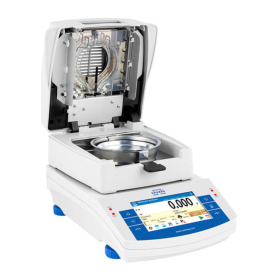
- Page 1 X2 Synergy MA X2 Moisture Analyzer USER MANUAL IMMU-21-03-10-16-EN www.radwag.com...
- Page 2 If you are reading this, it means that you are bound to achieve success. You have purchased a device that has been designed and manufactured to give you years of service. Congratulations and thank you for selecting RADWAG product. OCTOBER 2016...
-
Page 3: Table Of Contents
Contents 1. GENERAL INFORMATION ..............6 2. GENERAL SAFETY PRECAUTIONS ............7 2.1. Warning Symbols and Signals ..............7 Warning Descriptions ..................7 2.1.1. Warning Symbols ..................8 2.1.2. 2.2. Precautions ................... 8 2.3. Intended Use ..................9 2.4. Warranty Conditions ................9 2.5. - Page 4 9.2. Logging ....................31 9.3. Units....................32 9.4. Weighing Unit Selection ................ 32 9.5. Weighing Units Accessibility ..............33 9.6. Start Unit Selection ................33 9.7. User-defined Unit ................. 34 9.8. Balance Zeroing ................... 34 9.9. Balance Taring ..................34 9.10.
- Page 5 16.1. Selecting Optimum Mass for a Sample ............ 66 16.2. Influence of Sample Weight on Measurement Result Repeatability ....67 16.3. Drying Temperature ................67 16.4. Selecting Drying Profile ................. 67 16.5. Drying Time ..................68 16.6. Drying Profile Analysis ................69 17.
-
Page 6: General Information
1. GENERAL INFORMATION Dimensions: Connectors: 1. Power supplier connector 2. USB 2 type B connector 3. USB 1 type A connector 4. ETHERNET connector 5. COM connector Diagrams of connection cables: Balance – computer cable (RS232) Balance – printer cable (CITIZEN, EPSON) - 6 -... -
Page 7: General Safety Precautions
TECHNICAL SPECIFICATIONS Balance type MA 50/1.X2 MA 50.X2 MA 210.X2 110.X2 Max capacity 50 g 50 g 110 g 210 g Reading unit 0.1 mg 1 mg 1 mg 1 mg Tare range - 50 g - 50 g - 110 g - 210 g Maximum sample weight 50 g... -
Page 8: Precautions
2.1.2. Warning Symbols Electric shock Acid / Corrosion Potential danger Flammable or explosive substances Toxic substances Hot surface 2.2. Precautions WARNING! Adherence to safety information and user manual guidelines is required in order to prevent risk of health damage and even death. WARNING: Nominal voltage for a moisture analyzer is 230V AC. -
Page 9: Intended Use
CAUTION: Corrosion: substances that release aggressive vapours (e.g. acids) during the heating process. While drying such substances it is recommended to work with small samples. Otherwise, vapours can condense on cold housing parts and cause corrosion. WARNING: Fire or explosion: flammable or explosive substances, substances containing solvents or releasing flammable or explosive gases or vapours. -
Page 10: Precautions
2.5. Precautions RADWAG moisture analyzer adheres to all binding safety regulations. Nevertheless there are exceptional circumstances that may cause danger. Do not open the instrument’s housing. Inside there are no parts that would require maintenance, repair or replacement carried out by a user. -
Page 11: User Manual Significance
Do not make any design modifications. Additional equipment compatible with the moisture analyzer and spare parts should be supplied by RADWAG or an authorized distributor. 2.10. Protective Clothing While working with the instrument use protective clothing, this is to take safety precautions against potential hazards source of which might be tested samples and ingredients. -
Page 12: Transport And Storage
3. TRANSPORT AND STORAGE 3.1. Delivery Checklist Upon delivery it is necessary to check the package, make sure that your package bears no signs of damage. 3.2. Package Keep all package elements should your device be transported in the future. Remember that only original packaging can be used for shipping purposes. -
Page 13: Unpacking
4.2. Unpacking Carefully take the device out of the packaging, remove the transport lock and gently place the moisture analyzer at its workplace. Install the weighing pan and accessories following the diagram below: Accessories installation: Install: Drying chamber base insert (1), Anti-draft chamber (2), Pan handle (3), Cross-shaped holder (4),... -
Page 14: Maintenance Activities
4.5. Maintenance Activities 1. Disassembly a weighing pan and other detachable components (the components differ depending on a balance type – see Unpacking and Installation section). Be careful while detaching the components so as not to cause any damages to the balance mechanism. -
Page 15: Powering The Device
In case of a daily maintenance: 1. Remove the dirt using cloth dipped in warm water. 2. For best results, add a little dishwashing detergent. Cleaning powder-coated components: For preliminary cleaning stage you need running water or wet sponge featuring large holes, this will help you to remove loose, heavy dirt. -
Page 16: Start-Up
5. START-UP • Plug the power adapter to a socket, next connect the connector to port located at the back of the housing. • Press button located in the top right hand corner of the terminal. • Wait until start-up procedure is completed, the home screen of balance software is displayed automatically. -
Page 17: Weighing Mode Home Screen
7. WEIGHING MODE HOME SCREEN 7.1. Weighing Window The main window of balance software can be divided into 3 sections: • Top section displaying data on active working mode (pictogram and name), metrologically important data and button enabling selection of functions available for a particular working mode: •... -
Page 18: Drying Window
7.2. Drying Window The main window of balance software can be divided into 3 sections: • Top section displaying data on active working mode (pictogram and name), metrologically important data and button enabling selection of functions available for a particular working mode: •... -
Page 19: Entering Balance Menu
8. ENTERING BALANCE MENU Operation of balance software menu is intuitive and uncomplicated. The touch panel makes the software operation easy. Pressing a function key, a soft key or an area on the display initiates an assigned function or process. 8.1. -
Page 20: Soft Keys List
8.3. Soft Keys List Press to enter the main Press to clear the editing field. menu. Press to enable / disable an on- Press to scroll the menu screen keyboard. „up”, or „down”. Press to export databases (key active Press to confirm changes. upon plugging a pen drive). -
Page 21: Return To Weighing Mode
• Text field with function assigned: Press to develop an internal adjustment operation (internal adjustment function assigned to the text field). • Functions selections pictogram: CAUTION! For instruction on configuration of buttons, labels and text fields refer to section 8.6 of this user manual. -
Page 22: Buttons, Labels And Text Fields Configuration
8.6. Buttons, Labels and Text Fields Configuration Area beneath weight indication section can be freely programmed. It is divided into active fields taking form of a table: 3 rows, 10 columns. The division lines presented above are not visible on the balance screen, they serve only for informative purposes. - Page 23 Exemplary arrangement of widgets: 1. Always click extreme left side of a particular field that is to hold a selected <Widget>. 2. A new widget can only take such area that holds no other widgets yet. The software automatically detects which widgets can be applied for a particular area, this is conditioned by widget dimensions.
-
Page 24: Quick Access Keys
4. In order to rearrange widgets layout, it is necessary to delete already applied widgets first, and define new arrangement of buttons, labels and text fields next. 8.6.1. Quick Access Keys You can define quick access keys, the keys are displayed underneath weight indication section. - Page 25 selected displayed automatically on a home screen. Quick access keys list: Modes featuring the Function Accept/Print All modes Weighing mode Print header exclusively Weighing mode Print footer exclusively Zero All modes Tare All modes Set tare All modes Change unit Weighing mode exclusively Select unit...
-
Page 26: Labels
Hide/show last digit Weighing mode exclusively Drying mode Drying mode exclusively Drying mode Drying profile exclusively Drying mode Finish mode exclusively Drying mode Printout interval and unit exclusively Drying mode Open/close cover exclusively Drying mode Start exclusively 8.6.2. Labels You can select label size and type of information to be displayed for a particular label. In order to select a particular label, use a list of available labels. - Page 27 Select data to be displayed. The selected label is displayed automatically on a home screen. Label information types: Label information type Modes featuring the information Date All modes Time All modes Date and time All modes Net weight All modes Tare All modes Gross weight...
-
Page 28: Text Fields
Detailed description for a given information type is provided within section overviewing a respective mode. 8.6.3. Text Fields You can select text field size and type of information to be displayed in the first and the second line of the field, plus you can decide on a function that is to be assigned to a particular text field. -
Page 29: Bargraphs
Line 2: e.g. variable {3}, variable for current time displaying (other variables refer to point for non-standard printouts defining), Function: e.g. adjustment. When all text field parameters have been defined, the window displays respective values. defined text field displayed automatically on a home screen. 8.6.4. - Page 30 Procedure: Press and hold for a while the spot where bargraph is to be placed. Select bargraph and its size. selected bargraph displayed automatically on a home screen. - 30 -...
-
Page 31: Weighing Operation
9. WEIGHING OPERATION Load a weighed object on a balance weighing pan. On stabilization of weighing result, indicated by stability marker visible on the left side of balance display, read the measurement result. Record / printout of the measurement result is available on pressing <PRINT> key: •... -
Page 32: Units
2. Select <Admin> option, the software activates an on-screen keyboard, use it to enter operator’s password: „1111”, 3. Press button to confirm, home screen of the software is displayed again automatically, 4. When logged, add users and set the permissions levels (for the procedure of assigning permissions levels go further down this user manual). -
Page 33: Weighing Units Accessibility
Clicking the unit triggers its replacement, the clicked unit is replaced with the unit that is next on the list of available units. Another option for unit replacement is selecting a particular unit out of the units list, to view the list click key (if displayed in an information section). -
Page 34: User-Defined Unit
9.7. User-defined Unit You may declare two units. Displayed value of a user-defined unit is a multiplication of measured mass value and a coefficient specified for the particular user-defined unit. The units can be freely named with use of 3 characters maximum. By default the names are displayed as [u1] –... - Page 35 Manual Tare Determination Procedure: 1. While in optional mode press quick access key, 2. An on-screen numeric keyboard is displayed, 3. Enter tare value and press key, 4. The balance returns to the weighing mode, and the display indicates entered tare value with minus ‘–‘...
-
Page 36: Weighing Mode Settings
9.10. Weighing Mode Settings The software allows setup of operating parameters (filters, value release and autozero function, deleting the last digit and other settings) separately for each working mode. It enables customizing the instrument and utilizing its properties depending on your needs and expectations, or on specific requirements for selected working mode (e.g. -
Page 37: Proximity Sensors
Autozero function The software features an autozero function (Auto) ensuring precise mass indication. This function automatically controls and corrects zero indication. When Autozero is enabled, it compares balance indications at declared time interval e.g. 1s, provided that weighing pan is unloaded and display indication is close to zero. -
Page 38: Print Mode
7. The balance cancels tare value (packaging weight recorded in balance storage during the first step of the operating process) after the gross mass value (set in <AUTO THRES> parameter) has been exceeded; the entered tare value is cancelled automatically (Net marker disappears from the top section of the display), net weight is displayed;... -
Page 39: Minimum Sample Weight
(MSW) value and tare values for which the MSW value is to be obligatory. For standard X2 series models the values equal zero. Only authorized RADWAG employee or operator with Administrator permissions level, providing that balance factory settings enable this, can carry out procedure aiming to determine minimum sample weight and next enter the respective data. - Page 40 Example 1 for balance with d=0.0001 g: No. Tare value Minimum Operation Sample Weight 10.0000 g 1.0000 g Minimum sample weight refers to all net weights subjected to weighing in a tare container of mass 0,0001g – 9,9999g inclusive (<TARE> button used). program identifies setting...
-
Page 41: Cooperation With Titrators
Block – select to make the balance display respective pictograms informing on mass (whether it is out-of-tolerance low or out-of-tolerance high); with this option on, the software disables confirmation of the measurement that is out-of-tolerance low, Warn – select to make the balance display respective pictograms informing on mass (whether it is out-of-tolerance low or out-of-tolerance high);... -
Page 42: Miscellaneous
10. MISCELLANEOUS A user can set up parameters which influence balance operation. These parameters are to be found in parameters group MISC. Settings modification for particular parameters of this parameter group proceeds likewise as described in section 8 of this user manual. Menu language Language parameter enables selecting the language of the balance menu descriptions for unlogged user. - Page 43 Proximity sensors sensitivity adjustment Proximity sensors sensitivity parameter specifies distance within which the sensors can be operated, its scale is expressed in percent and it ranges from 0% to 100%. For lower percent value the proximity sensors operate at a shorter distance. Procedure Date Date parameter enables setting the current date.
-
Page 44: Adjustment
change of indication (no stability pictogram on the display) or pressing any key on the balance keypad. The display remains blank also when balance menu is entered. Auto switch-off <AUTO OFF> parameter enables automatic display deactivation (the parameter functioning is likewise to button functioning). -
Page 45: User Adjustment
6. Upon completed procedure “Remove weight” prompt is displayed. 7. Take the weight off the weighing pan, wait for <Adjustment> window to be displayed again. 11.2. User Adjustment User adjustment is carried out with an optional standard of mass ranging between 0,3 Max and Max. - Page 46 Step 1. Remove from the drying chamber the following: • disposable pan • drying pan handle • cross-shaped holder • drying chamber insert Step 2. Assemble drying components of temperature adjustment kit: • drying chamber shield thermometer holder thermometer Step 3. After assembling the kit start temperature adjustment process.
-
Page 47: Drying Process Test
Press key to confirm, the second step of adjustment starts. The moisture analyzer halogen lamp starts to operate and the drying chamber is heated as long as necessary to provide specified temperature, which is next maintained for 8 minutes. After 8 minutes a numeric keyboard is displayed. - Page 48 Procedure: 1. Set test parameters in accordance with instruction below and the displayed prompts. 2. Enter ADJUSTMENT menu and start <Temperature test> procedure. Enter: • testing temperature • permissible error • serial number of the temperature adjustment set Upon confirmation of serial number START message is displayed.
-
Page 49: Determining Printout Content
12. DETERMINING PRINTOUT CONTENT 12.1. Adjustment Report ADJUSTMENT REPORT is a group of parameters enabling to declare data that is to be printed on an adjustment printout. Variable Overview PROJECT Option enables naming the project (name associated with a particular type of weighing). -
Page 50: Drying Process Report Printout
12.2. Drying Process Report Printout Group of parameters enabling user to declare data that is to be printed on a Drying Process Report printout. The Drying Process Report is divided into three individually customized sections: the header, the measurement, the footer. The settings are valid for Drying Process mode exclusively. - Page 51 VARIABLE 2. Option enables printing out the value of Header VARIABLE 3 VARIABLE 3. Option enables printing out net weight value in a Header START MASS basic unit (calibration unit). Option enables printing out an empty separating Header EMPTY LINE line.
-
Page 52: Other Printouts
12.3. Other Printouts Group of parameters enabling to HEADER declare data that is to be printed on a header printout. Group of parameters enabling to declare data that is to be printed on a PRINTOUT measurement result printout. Group of parameters enabling to FOOTER declare data that is to be printed on a footer printout. - Page 53 GLP printout Footer VARIABLE 3 Option enables printing out the value of VARIABLE Header GLP printout Footer Option enables printing out net weight value in a GLP printout basic unit (calibration unit). TARE Option enables printing out the tare value in the GLP printout current unit.
-
Page 54: Non-Standard Printouts
12.4. Non-standard Printouts The balance software enables entering 100 non-standard printouts. Each of them can consist of approximately 1900 characters. Non-standard printout may include: • variables dependent on the working mode and other needs (mass, date etc.) • permanent text from the user menu. Non-standard printout can have approximately 1900 characters. - Page 55 Gross weight in current unit {147} Tare weight in current unit {150} Form feed for PCL printers {151} Paper crop for EPSON printers {155} Cooperation with RADWAG CONECT PC software {275} Ambient conditions readout date and time {276} THB: Temperature {277} THB: Humidity {278}...
- Page 56 Every single printout can contain max 1900 characters (letters, numerals, non-standard characters, spaces). A user can apply non-standard characters depending on type of data that is to be printed out. An example: “RADWAG” DATE: <current measurement date> TIME: <current measurement time> PRODUCT MASS: <current mass indication>...
-
Page 57: Variables
If you want to carry out HEADER or GLP or FOOTER printout using EPSON printer (equipped with autocutter blade) and crop the paper beneath the respective printout, then you have to select an option of non-standard printout comprising {151} variable, and set this option in header, GLP printout or footer settings, respectively (means for entering control codes are described in section 21 of this user manual). -
Page 58: Working Modes - General Information
13. WORKING MODES – GENERAL INFORMATION Standard version of X2 series balances feature the following working modes: Weighing Means of operation: weight of a load is determined through an indirect measurement. A balance measures gravitational force which attracts the load. An obtained result is processed to a digital format and displayed in a form of measurement result. -
Page 59: Parameters Related To A Working Mode
• wait for the available working modes list to be displayed, • select the working mode you need to operate. 13.3. Parameters Related to a Working Mode Each working mode has programmable parameters determining its functioning. Read point 9 of this user manual for description of possible settings for WEIGHING working mode. Settings for DRYING working mode are specified within its description. - Page 60 123456.for Weighing Reports 123456.wei Files can be read using ALIBI Reader by RADWAG that can be downloaded from the website: www.radwag.pl. AMBIENT CONDITIONS database serves informative purposes only. Using records preview option you can check ambient conditions and observe how they changed over time. The data saved to records can be printed by pressing pictogram located in the top bar.
-
Page 61: Products
14.2. Products Product database stores names of all products that can be weighed, counted, controlled. List of parameters defined for a product: 1. Name [product code] 2. Code [EAN code for a product] 3. EAN [nominal mass/single product mass] 4. Mass [nominal mass/single product mass] 5. -
Page 62: Drying Program
3. NIP 4. Address 5. Postal code 6. City 14.6. Drying Program Database of drying programs contains saved data on drying parameters which are activated to dry a product. List of parameters defined for drying mode: 1. Name 2. Code 3. -
Page 63: Weighing Records
3. Record name comprises date and time. CAUTION! The software saves ambient conditions record in a so called loop, i.e. when the measurement 10 001 is saved, the measurement 1 is automatically deleted from the balance’s memory. Records saved to balance memory cannot be deleted. -
Page 64: Sample Preparation For Drying
RADWAG moisture analyzer MA X2 series comprises two components: a precision balance and a drying chamber. Compared to standard moisture content determining methods, the measurements with application of RADWAG moisture analyzer is much quicker and does not require additional mathematical calculations (a result of moisture content is previewed on an ongoing basis during product testing process). - Page 65 be carried out as quickly as possible, so that a sample does not lose or absorb humidity from surrounding area. Applied sampling standards should match individual user needs and requirements of tested material, its consistence and sample size. Number of samples Increasing number of tested samples also increases statistic measurement certainty.
-
Page 66: Selection Of Drying Parameters
Sample distribution on a pan: Loose materials Dried in their natural state, i.e. in their natural form or disintegrated. Sample disintegration causes smaller dispersion between the following measurements. Sample mass should not be too high, and the sample should be evenly spread on whole surface of the drying pan. -
Page 67: Influence Of Sample Weight On Measurement Result Repeatability
16.2. Influence of Sample Weight on Measurement Result Repeatability Sample mass considerably influences repeatability of measurement results obtained on a moisture analyzer. Relation between sample mass and repeatability is presented in a table below. Sample weight Repeatability ±0.05% ~ 2g ±0.01% ~ 10g The above data refers to a model, uniform sample, containing no moisture due to the... -
Page 68: Drying Time
MILD profile Mild profile is used in case of drying substances that are sensitive to rapid heat emitted by filaments operating at full power in the initial stage of drying process. This profile prevents from decomposing of substances sensitive to heat by mild temperature increase in set amount of time (time interval has to be selected by tests). -
Page 69: Drying Profile Analysis
- User defined 2 (set moisture content change ratio ∆%M over time 60s) 16.6. Drying Profile Analysis For the first case, the drying profile is an asymptote. Moisture content value remains constant even after long drying time. Using this drying profile makes determination of humidity easy. -
Page 70: Drying Process Profile And Drying Parameters
17.1. Drying Process Profile and Drying Parameters Enter drying parameters settings and select mode type. Upon selection fields enabling setting profile parameters are displayed. Parameters depend on selected mode. Drying process mode parameter takes the following values: • STANDARD drying profile – For standard profile set drying temperature in which a sample is to be tested. -
Page 71: Automatic Finish Mode
CAUTION! For Step profile, set step temperature „1” and „2” and temperature of drying, set also time heating time in particular indirect temperatures (1 and 2). Time for heating in particular steps is counted from the moment of reaching a preset temperature for a particular step. 17.2. -
Page 72: Printout Interval
%FB - fat content in beef, measurement result is a percent value determining how much fat is contained within beef, - fat content in pork, measurement result is a percent value determining how much fat is contained within pork. 17.4. Printout interval The time interval between printouts in seconds ranging from 0 to 120. -
Page 73: Drying Process
19. DRYING PROCESS Drying process settings displayed information field above the buttons. Press Start button in order to run the drying process. Prompts messages displayed making moisture analyzer operation easier. Follow the prompts to correctly prepare the sample and to perform the process of humidity content determination for a tested sample. - Page 74 Indication equals ZERO, subsequent prompt is displayed and the pictogram on drying chamber status changes. Deposit sample on a weighing pan. Sample weight shall be selected on the basis of prior experience and tested material characteristics. On sample preparation and result stabilization close the drying chamber and confirm the operation by pressing key.
- Page 75 Information on the drying process is displayed, moisture analyzer proceeds to carrying it out accordingly to set parameters. Required mass measurements and calculations of tested sample moisture content performed, wherein calculations are a result of mass change. On process start, printout header is sent to a selected interface (accordingly to set printout options –...
- Page 76 An example of drying report: - 76 -...
-
Page 77: Communication
20. COMMUNICATION COMMUNICATION menu is comprised within Parameters menu. It is accessed by pressing key. The balance can communicate with a peripheral device, wherein the communication is established via the following ports: • COM 1 (RS232), • USB 1 type A, •... - Page 78 Pictogram for Wi-Fi network connection status: No. Pictogram Overview Balance connected, very strong signal Balance connected, strong signal Balance connected, poor signal Balance connected, very poor signal No connection (too poor signal or inaccessible selected network or invalid connection parameters – password, IP, etc.) Exemplary settings for Wi-Fi port: CAUTION! The above presented settings serve information purposes only.
- Page 79 With DHCP set to NO value, enter manually: <IP>, <MASK>, <DEFAULT GATE> parameters. With DHCP set to YES value, the balance software automatically reads and displays data assigned by Wi-Fi router by means of which the balance is to be connected, 3.
-
Page 80: Usb Ports
(password etc.), check the parameters and try to reestablish connection. 10. If you fail to reestablish connection, contact RADWAG service. The selected network and parameters for connection are stored in the balance program. The program connects to the network using the stored parameters each time the balance is activated. - Page 81 To carry out this procedure, you need a respective driver installer which may be either downloaded from the website www.radwag.pl or taken from a CD with manuals: R X2 SERIES RADWAG USB DRIVER x.x.x.exe. Procedure: 1. Run driver installer. Startup dialog window: Select language version.
- Page 82 2. Having completed driver installation, connect balance to a computer, use 1,8-meter long USB A/B cable maximally (in case of already connected balance, it is necessary to disconnect it and using USB cable connect the balance again). - 82 -...
- Page 83 3. The system detects the new USB device and automatically starts searching a respective driver. 4. Go to Device Manager and check number assigned to virtual COM port. For this very case it is STMicroelectronics Virtual COM Port (COM8). 5. Set balance parameters: select USB value for parameter COMPUTER/PORT. 6.
-
Page 84: Peripherals
21. PERIPHERALS PERIPHERALS menu is comprised within Parameters menu. It is accessed by pressing key. The menu features list of devices that can cooperate with the balance. 21.1. Computer Carry out configuration using <Computer> submenu. Procedure: 1. Press key, next press: <Peripherals / Computer>, 2. - Page 85 basic special characters written using key combination of a letter and right ‘Alt’ button. Other special characters are not operated in Free Link printout option. • port settings o settings related to a port selected for computer connection CAUTION: for Ethernet and Wi-Fi port Timeout parameter is on. The parameter specifies time delay –...
-
Page 86: Printer
USB – USB 1 port type A, the one to which a PCL printer or EPSON printer is connected Ethernet – port sending data to a dedicated RADWAG software, e.g. PW-WIN, operated on a computer connected to a balance via network. - Page 87 On Free Link printout option set (keyboard emulator) all languages without special characters are operated by means of ‘QWERTY’ keyboard. Additionally, the following languages are operated: • Polish for ‘Polish (Programmers) keyboard’. In printer options located in the balance select Windows-1250 code page (Central European, Latin-2). The following Polish diacritical signs are added: ą, ć, ę, ł, ń, ó, ś, ż, ź.
- Page 88 data taken from the balance (this possibility is available only for printers with such option – see a user manual of the printer). CAUTION! CODES MUST BE ENTERED IN A HEXADECIMAL FORM! Example balance settings for correct cooperation (printout of Polish signs) with EPSON thermal printer connected to RS232 port: 1.
-
Page 89: Usb Flash Drive
21.3. USB Flash Drive The balance software enables record of measurement data on an external flash drive. Procedure: 1. Plug a USB flash drive into USB 1 port, type A. 2. Set <PENDRIVE> option for <PERIPHERALS/PRINTER/PORT>. 3. Set file format: *.txt or *.csv. 4. -
Page 90: Ambient Conditions Module
4. Set balance parameters for cooperation with barcode reader: 5. <PORT> - selection of the port, to which the barcode reader is to be connected: Accessible options: NONE, COM 1 21.5. Ambient Conditions Module THB 3/5 module can be connected to the balance via COM1 port. In order to provide correct cooperation enter connected module address and baud rate for the port (port settings) to which the ambient conditions module is connected (the address and baud rate data is to be found on an ambient conditions data plate). - Page 91 Min temperature – min balance temperature, for lower temperature values the thermometer pictogram is red Max temperature – max balance temperature, for higher temperature values the thermometer pictogram is red Temperature ∆t/h – maximum balance temperature change rate, for higher change rate values the balance displays blinking red thermometer pictogram In order to enable/disable parameter visibility go to service menu.
-
Page 92: Communication Protocol
General information A. A character based communication protocol balance-terminal is designed for establishing communication between a RADWAG balance and a peripheral device via RS-232C serial interface. B. It consists of commands sent from a peripheral device to the balance and responses from the balance. -
Page 93: Response Format
Internal adjustment performance Disable automatic internal adjustment of the balance Enable automatic internal adjustment of the balance Lock balance keypad Unlock balance keypad Give available working modes Set working mode Give current working mode Give accessible units Set unit Give current unit Activate sound signal Send all implemented commands Give balance type... - Page 94 COMMANDS OVERVIEW Zero balance Format: Z CR LF Response options: Z_A CR LF - command understood and in progress Z_D CR LF - command carried out Z_A CR LF - command understood and in progress Z_^ CR LF - command understood but zeroing range is exceeded Z_A CR LF - command understood and in progress Z_E CR LF...
- Page 95 An example: S CR LF - command send form a computer S _ A CR LF - command understood and in progress S _ _ _ _ - _ _ _ _ _ _ 8 . 5 _ g _ _ CR - command carried out, response: mass value in a basic measuring unit.
- Page 96 where: _ - space Switch on continuous transmission in a basic measuring unit Format: C1 CR LF Response options: C1_I CR LF - command understood but not accessible at this moment C1_A CR LF - command understood and in progress MASS FRAME - response: mass value in a basic measuring unit Response format: 7-15...
- Page 97 Give value of max checkweighing threshold Format: OUH CR LF Response: UH_MASA CR LF - command carried out Response format: 4-12 space mass space unit space Mass - 9 characters with right justification Unit - 3 characters with left justification Set mass value of a single item (only for PARTS COUNTING) Format: SM_XXXXX CR LF, where: _ - space, XXXXX –...
- Page 98 For non-verified balances the command inhibits internal adjustment until it is enabled via IC0 command or until the balance is turned off. The command does not modify settings specifying calibration start. Enable automatic internal adjustment of the balance Format: IC0 CR LF Response options: IC0_I CR LF - command understood but not accessible at this moment...
- Page 99 2_” Parts counting” <CR><LF> in return: mode number + name 19_” Drying” <CR><LF> OK <CR><LF> – command carried out Set working mode Command overview: Command sets particular working mode. Format: OMS_n <CR><LF> Response options: OMS_OK <CR><LF> – command carried out –...
- Page 100 pressing). An example: Command: US_mg<CR><LF> – set „mg” unit Response: US_mg_OK<CR><LF> – „mg” set as a current unit Give current unit Command overview: command returns current unit. Format: UG <CR><LF> Response options: UG_x_OK<CR><LF> – command carried out, response: current unit UG_I <CR><LF>...
- Page 101 An example: Command: FS <CR><LF> – return Max capacity Response: FS_A_”220.0000” – Max capacity: ”220 g” Give program version Format: RV <CR><LF> Response options: RV_A_”x” <CR><LF> - command understood, response: program version RV_I <CR><LF> - command understood but not accessible at this moment x –...
- Page 102 n → 1 – very fast 2 – fast 3 – average 4 – slow 5 – very slow CAUTION! The numbering is assigned to a particular filter name and it is identical for all balance types. The command changes settings for a current working mode if, for a particular balance type, filter settings are assigned to the working mode.
- Page 103 Response options: LOGIN OK CR LF – command understood, new operator logged in – command understood, name or password error occurrence, LOGIN ERRROR CR LF logging operation cannot be carried out ES CR LF – command not understood (format error) User logout Format: LOGOUT CR LF Response options:...
-
Page 104: Manual Printout / Automatic Printout
Mass 9 characters with decimal point - right justification Unit 3 characters - left justification 23.3. Manual Printout / Automatic Printout MA X2 moisture analyzer enables generating manual or automatic printouts. • Manual printout: on stabilization of indication (measurement result) press key. -
Page 105: Error Messages
25. ERROR MESSAGES 26. USE OF MOISTURE ANALYZER For measurement temperatures ranging from 161°C to 250°C the time of maintaining the temperature during the measurement is estimated proportionally, ~15 hours for 161°C – 10 min for 250°C. For a drying process carried out in 250°C, Max temp is maintained for 10 min, next the program automatically lowers the temperature (drying is not interrupted) to 160°C. -
Page 106: Maintenance Activities
27. MAINTENANCE ACTIVITIES This section describes how to maintain the moisture analyzer in good condition, and how to replace its faulty components (filaments, fuses). 27.1. Cleaning Moisture Analyzer Components In order to ensure required measuring accuracy, the moisture analyzer has to be used and stored clean. -
Page 107: Cleaning Temperature Sensor
27.2. Cleaning Temperature Sensor To ensure correct temperature measurement make sure that the temperature sensor is clean (1). Take extra precautions while cleaning the device. Clean the moisture analyzer using soft fabrics and mild cleaning agents. Do not use any abrasive agents or solvents as it may cause damage to the sensor. -
Page 108: Additional Equipment
28. ADDITIONAL EQUIPMENT Type Name P0151 Cable RS232 for EPSON printer EPSON Impact/thermal printer CITIZEN Labeller PCL Printer Anti-vibration table PC keyboard – USB type 29. INFORMATION ON MOISTURE ANALYZER This menu provides you with information on moisture analyzer and its installed software. The parameters are strictly informative. - Page 109 - 109 -...
- Page 110 - 110 -...
Need help?
Do you have a question about the MA X2 Synergy and is the answer not in the manual?
Questions and answers