Table of Contents
Advertisement
Advertisement
Table of Contents

Related Manuals for MSI MS-7181


Summary of Contents for MSI MS-7181
- Page 1 MS-7181 (v10) Micro-ATX Mainboard...
-
Page 2: Table Of Contents
CONTENTS Chapter 1. Getting Started ................... 1-1 Mainboard Specifications .................. 1-2 Mainboard Layout ....................1-4 Packing Contents ....................1-5 Chapter 2. Hardware Setup ................. 2-1 Quick Components Guide .................. 2-2 Central Processing Unit: CPU ................2-3 Memory ....................... 2-6 Power Supply ..................... 2-8 ATX 20-Pin Power Connector: JWR1 ............... - Page 3 Chapter 3. BIOS Setup ................... 3-1 Entering Setup ....................3-2 The Main Menu ....................3-4 Standard CMOS Features .................. 3-6 Advanced BIOS Features .................. 3-8 Advanced Chipset Features ................3-10 Integrated Peripherals ..................3-13 Power Management Setup ................3-16 PNP/PCI Configurations ..................3-19 H/W Monitor ......................
-
Page 4: Chapter 1. Getting Started
Chapter 1. Getting Started Getting Started Thank you for purchasing the K8MM2 (MS-7181 v1.x) series, an excellent Micro-ATX mainboard from MSI. Based on the innovative VIA K8M800 and VIA VT8237R chipsets for optimal system efficiency, the K8MM2 serias mainboard accommodates latest AMD K8 processor in the 754-pin lidded ceramic micro PGA package, and supports up to 2 DIMMs to provide the maximum of 2 GB memory capacity. -
Page 5: Mainboard Specifications
MS-7181 Micro-ATX Mainboard Mainboard Specifications ® Supports 64-bit AMD K8 Athlon 64/ Sempron processor (Socket 754). Supports 3700+ or higher CPU. Chipset VIA K8M800 Chipset -HyperTransport connection to AMD K8 Athlon64/ Sempron processor -8 or 16 bit control/address/data transfer both directions -800/600/400/200 MHz “Double Data Rate”... - Page 6 Getting Started - 1 Aux-In pinheader - 1 audio port (Line-in/Line-out/MIC) - 8 USB 1.1/2.0 ports (Rear * 4/ Front * 4) Audio AC’97 link controller integrated in VIA VT8237R. 6 channels software audio codec VIA VT1617A - Compliance with AC97 v2.3 Spec. - Meet PC2001 audio performance requirement.
-
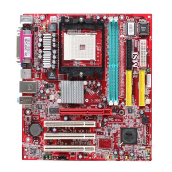
Page 7: Mainboard Layout
Top : Parallel Port Bottom: COM Port VGA Port USB ports Top: LAN Jack Bottom: USB ports K8M800 Line-In Line-Out CPUFAN1 B:Mic SFAN1 VT6103L AGP1 PCI1 BATT PCI2 VT8237R PCI3 VT1617A JFP1 JAUD1 JAUX1 JUSB2 JUSB1 K8MM2 (MS-7181 v1.X) Mainboard... -
Page 8: Chapter 2. Hardware Setup
Hardware Setup Chapter 2. Hardware Setup Hardware Setup This chapter provides you with the information about hardware setup procedures. While doing the installation, be careful in holding the com- ponents and follow the installation procedures. For some components, if you install in the wrong orientation, the components will not work properly. -
Page 9: Quick Components Guide
MS-7181 Micro-ATX Mainboard Quick Components Guide JPW1, p.2-8 DIMM1-2, p.2-6 CPU, p.2-3 FDD1, p.2-14 JWR1, p.2-8 I/O Ports, p.2-9 JBAT1, p.2-21 IDE1, IDE2, p.2-15 SFAN1, p.2-14 CPUFAN1, p.2-14 AGP slot, p.2-22 PCI slots, p.2-22 JFP1, p.2-16 JAUX1, p.2-18 JUSB1/2, p.2-17... -
Page 10: Central Processing Unit: Cpu
Memory Speed/CPU FSB Support Matrix DDR 400 DDR 266 DDR 333 FSB 800 MSI Reminds You... Overheating Overheating will seriously damage the CPU and system, always make sure the cooling fan can work properly to protect the CPU from overheating. - Page 11 MS-7181 Micro-ATX Mainboard CPU Installation Procedures for Socket 754 Please turn off the power and unplug the power cord before installing the CPU. Pull the lever sideways away from the socket. Make sure to raise the lever up to a 90-de- gree angle.
- Page 12 Fixed Bolt. Lift up the in- CPUFAN1 connector on the tensive fixed lever. board MSI Reminds You... While disconnecting the Safety Hook from the fixed bolt, it is necessary to keep an eye on S a f e t y...
-
Page 13: Memory
The mainboard provides two slots for 184-pin DDR SDRAM DIMM (Double In-Line Memory Module) modules and supports up to 2GB memory size. You can install PC3200/DDR400, PC2700/DDR333 & PC2100/DDR266 modules on the DDR DIMM slots (DDR 1~2). For the updated supporting memory modules, please visit http://www.msi.com.tw/ program/products/mainboard/mbd/pro_mbd_trp_list.php. DDR DIMM Slots (DIMM1~2) - Page 14 3. The plastic clip at each side of the DIMM slot will automatically close. Notch Volt MSI Reminds You... You can barely see the golden finger if the module is properly inserted in the socket.
-
Page 15: Power Supply
MS-7181 Micro-ATX Mainboard Power Supply The mainboard supports ATX power supply for the power system. Before inserting the power supply connector, always make sure that all components are installed properly to ensure that no damage will be caused. ATX 20-Pin Power Connector: JWR1 This connector allows you to connect to an ATX power supply. -
Page 16: Back Panel
Hardware Setup Back Panel View of the Back Panel The back panel provides the following connectors: L-in Parallel Mouse Keyboard USB Ports VGA Port USB Ports L-out COM 1 Serial Port: COM1 The mainboard provides one 9-pin mail DIN connector as serial port COM1. The serial port is a 16550A high speed communication port that sends/receives 16 bytes FIFOs. -
Page 17: Mouse Connector
MS-7181 Micro-ATX Mainboard Mouse Connector The mainboard provides a standard PS/2 ® mouse mini DIN connector for attaching a ® ® PS/2 mouse. You can plug a PS/2 mouse directly into this connector. The connector location and pin assignments are as follows. -
Page 18: Usb Ports
Hardware Setup USB Ports The mainboard provides a UHCI (Universal Host Controller Interface) Universal Serial Bus root for attaching USB devices such as keyboard, mouse or other USB-compat- ible devices. You can plug USB devices directly into the ports. Pin Definition SIGNAL DESCRIPTION 1 2 3 4... -
Page 19: Audio Port Connectors
MS-7181 Micro-ATX Mainboard Audio Port Connectors Line Out is a connector for Speakers or Headphones. Line In is used for external CD player, Tape player, or other audio devices. Mic is a connector for microphones. Line In Line Out MSI Reminds You... -
Page 20: Parallel Port
Hardware Setup Parallel Port The mainboard provides a 25-pin female centronic connector as LPT. A parallel port is a standard printer port that supports Enhanced Parallel Port (EPP) and Extended Capabilities Parallel Port (ECP) mode. Pin Definition SIGNAL DESCRIPTION STROBE Strobe DATA0 Data0... -
Page 21: Floppy Disk Drive Connector: Fdd1
MS-7181 Micro-ATX Mainboard Connectors The mainboard provides connectors to connect FDD, IDE HDD, front panel of the system case, audio ports, USB Ports, and CPU/System FANs. Floppy Disk Drive Connector: FDD1 The mainboard provides a standard floppy disk drive connector that supports 360KB, 720KB, 1.2MB, 1.44MB and 2.88MB floppy disk types. -
Page 22: Hard Disk Connectors: Ide1 & Ide2
(reserved for future BIOS), and other devices. IDE1 IDE2 MSI Reminds You... If you install two hard disks on cable, you must configure the second drive to Slave mode by setting its jumper. Refer to the hard disk documentation supplied by hard disk vendors for jumper setting instructions. -
Page 23: Front Panel Connectors: Jfp1
MS-7181 Micro-ATX Mainboard Front Panel Connectors: JFP1 The mainboard provides two front panel connectors for electrical connection to the ® front panel switches and LEDs. JFP1 is compliant with Intel Front Panel I/O Connec- tivity Design Guide. Power Power JFP1... -
Page 24: Aux Line-In Connector: Jaux1
Description USBPWR USBPWR USBP2- USBP3- JUSB1/JUSB2 USBP2+ USBP3+ OC # USB 2.0 Bracket Connected to JUSB1 (optional) or JUSB2 MSI Reminds You... Note that the pins of VCC and GND must be connected correctly, or itmay cause some damage. 2-17... -
Page 25: Front Panel Audio Connector: Jaud1
MS-7181 Micro-ATX Mainboard Front Panel Audio Connector: JAUD1 The mainboard provides one front audio connector for users to connect the optional audio cable. JAUD1 Pin Definition SIGNAL DESCRIPTION AUD_MIC Front panel microphone input signal AUD_GND Ground used by analog audio circuits... -
Page 26: Jumpers
JBAT1 Keep Data Clear Data MSI Reminds You... You can clear CMOS by shorting 2-3 pin while the system is off. Then return to 1-2 pin position. Avoid clearing the CMOS while the system is on; it will damage the mainboard. -
Page 27: Slots
MS-7181 Micro-ATX Mainboard Slots The motherboard provides one AGP slot and three 32-bit PCI bus slots. AGP (Accelerated Graphics Port) Slot The AGP slot allows you to insert the AGP graphics card. AGP is an interface speci- fication designed for the throughput demands of 3D graphics. It introduces a 66MHz, 32-bit channel for the graphics controller to directly access main memory. -
Page 28: Chapter 3. Bios Setup
An error message appears on the screen during system boot up, and requests you to run SETUP. You want to change the default settings for customized features. MSI Reminds You... 1. The items under each BIOS category described in this chapter are under continuous update for better system performance. -
Page 29: Entering Setup
MS-7181 Micro-ATX Mainboard Entering Setup Power on the computer and the system will start POST (Power On Self Test) process. When the message below appears on the screen, press <DEL> key to enter Setup. Press DEL to enter SETUP If the message disappears before you respond and you still wish to enter Setup, restart the system by turning it OFF and On or pressing the RESET button. - Page 30 BIOS Setup Control Keys <↑> Move to the previous item <↓> Move to the next item <←> Move to the item in the left hand <→> Move to the item in the right hand <Enter> Select the item <Esc> Jumps to the Exit menu or returns to the main menu from a submenu <+/PU>...
-
Page 31: The Main Menu
MS-7181 Micro-ATX Mainboard The Main Menu ® Once you enter Phoenix-Award BIOS CMOS Setup Utility, the Main Menu will appear on the screen. The Main Menu allows you to select from the eleven setup functions and two exit choices. Use arrow keys to select among the items and press <Enter>... - Page 32 BIOS Setup Save & Exit Setup Save changes to CMOS and exit setup. Exit Without Saving Abandon all changes and exit setup.
-
Page 33: Standard Cmos Features
MS-7181 Micro-ATX Mainboard Standard CMOS Features The items in Standard CMOS Features Menu includes some basic setup items. Use the arrow keys to highlight the item and then use the <PgUp> or <PgDn> keys to select the value you want in each item. - Page 34 BIOS Setup Drive A This item allows you to set the type of floppy drive installed. Available options: [None], [360K, 5.25 in.], [1.2M, 5.25 in.], [720K, 3.5 in.], [1.44M, 3.5 in.], [2.88M, 3.5 in.]. Halt On The setting determines whether the system will stop if an error is detected at boot. Available options are: [All Errors] The system stops when any error is detected.
-
Page 35: Advanced Bios Features
MS-7181 Micro-ATX Mainboard Advanced BIOS Features Quick Boot Setting the item to Enabled allows the system to boot within 5 seconds since it will skip some check items. Setting options: [Enabled], [Disabled]. Boot Sequence Press <Enter> to enter the sub-menu and the following screen appears:... - Page 36 BIOS Setup Hard Disk Boot Priority Press <Enter> to enter the sub-menu and the following screen appears: In the sub-menu, it shows the hard disks information that was installed in the system, and you can set the hard disk boot priority. IOAPIC Function This field is used to enable or disable the APIC (Advanced Programmable Interrupt Controller).
-
Page 37: Advanced Chipset Features
MS-7181 Micro-ATX Mainboard Advanced Chipset Features AGP & P2P Bridge Control Press <Enter> to enter the sub-menu and the following screen appears: AGP Aperture Size This setting controls just how much system RAM can be allocated to AGP for video purposes. The aperture is a portion of the PCI memory address range dedicated to graphics memory address space. - Page 38 BIOS Setup DRAM Configuration Press <Enter> to enter the sub-menu and the following screen appears: Timing Mode This field has the capacity to automatically detect all of the DRAM timing. If you set this field to [Manual], the following fields will be selectable. Setting options: [Auto], [Manual].
- Page 39 MS-7181 Micro-ATX Mainboard 1T/2T Memory Timing This setting controls the SDRAM command rate. Selecting [Auto] allows SDRAM signal controller to run at 1T (T=clock cycles) rate. Selecting [1T] makes SDRAM signal controller run at 2T rate. 1T is faster than 2T. Setting options: [1T], [2T].
-
Page 40: Integrated Peripherals
BIOS Setup Integrated Peripherals AC97 Controller Select [Enabled] if you intend to use the onboard audio AC97 controller. Disable the controller if you want to use other controller cards to connect an audio device. Setting options: [Enabled], [Disabled]. Onboard LAN Control This setting controls the onboard Intel LAN controller. - Page 41 MS-7181 Micro-ATX Mainboard IDE Devices Configuration Press <Enter> to enter the sub-menu and the following screen appears: IDE DMA transfer access Setting to [Enabled] will open DMA bus master and execute DMA action in DOS, which will make the data transferring faster. Setting options: [Disabled], [Enabled].
- Page 42 BIOS Setup [3BC/IRQ7] Line Printer port 0 [278/IRQ5] Line Printer port 2 [378/IRQ7] Line Printer port 1 Parallel Port Mode This field selects the operation mode for the onboard parallel port. Setting options: [SPP] Standard Parallel Port [EPP] Enhanced Parallel Port [ECP] Extended Capability Port [ECP + EPP]...
-
Page 43: Power Management Setup
MS-7181 Micro-ATX Mainboard Power Management Setup MSI Reminds You... S3-related functions described in this section are available only when your BIOS supports S3 sleep mode. ACPI Function This item is to activate the ACPI (Advanced Configuration and Power Management Interface) Function. If your operating system is ACPI-aware, such as Windows 2000/ XP, select [Enabled]. - Page 44 BIOS Setup [Suspend] When you press the power button, the computer enters the suspend/ sleep mode, but if the button is pressed for more than four seconds, the computer is turned off. Restore on AC/Power Loss This setting specifies whether your system will reboot after a power failure or interrupt occurs.
- Page 45 MS-7181 Micro-ATX Mainboard Resume by RTC Alarm This is used to enable or disable the feature of booting up the system on a scheduled time/date from the S3, S4, and S5 power off state. Setting options: [Disabled], [Enabled]. Date (of Month) Alarm The field specifies the date for Resume by RTC Alarm.
-
Page 46: Pnp/Pci Configurations
BIOS Setup PNP/PCI Configurations This section describes configuring the PCI bus system and PnP (Plug & Play) feature. PCI, or Peripheral Component Interconnect, is a system which allows I/O devices to operate at speeds nearing the speed the CPU itself uses when communicating with its special components. - Page 47 MS-7181 Micro-ATX Mainboard IRQ 3/4/5/7/9/10/11/14/15 These items specify the bus where the specified IRQ line is used. The settings determine if AMIBIOS should remove an IRQ from the pool of available IRQs passed to devices that are configurable by the system BIOS. The available IRQ pool is determined by reading the ESCD NVRAM.
-
Page 48: H/W Monitor
CPU’s from overheading due to the heavy working loading. Setting options: [Disabled], [Auto]. MSI Reminds You... 1. For the purpose of ensuring the stability of Cool'n'Quiet function, it is always recommended to have the memories plugged in DIMM1. - Page 49 MS-7181 Micro-ATX Mainboard Smart CPU Fan The mainboard provides the Smart Fan system which can control the fan speed automatically depending on the current temperature to keep it with in a specific range. Setting options: [Disabled],[40 C/104 F],[50 C/122 F],[60...
-
Page 50: Load Optimized Defaults
BIOS Setup Load Optimized Defaults The option on the main menu allows users to restore all of the BIOS settings to the Optimized values. The Optimized Defaults are the default values set by the mainboard manufacturer specifically for optimal performance of the mainboard. When you select Load Optimized Defaults, a message as below appears: Pressing Y loads the default factory settings for optimal system performance.
Need help?
Do you have a question about the MS-7181 and is the answer not in the manual?
Questions and answers