Table of Contents
Advertisement
Advertisement
Table of Contents

Related Manuals for MSI K8MM3 Series


Summary of Contents for MSI K8MM3 Series
- Page 1 K8MM3 Series MS-7181 (v2.X) Micro-ATX Mainboard G52-M7181X4...
- Page 2 FCC-B Radio Frequency Interference Statement This equipment has been tested and found to comply with the limits for a class B digital device, pursuant to part 15 of the FCC rules. These limits are designed to provide reasonable protection against harmful interference in a residential installation. This equipment generates, uses and can radiate radio frequency energy and, if not installed and used in accordance with the instruction manual, may cause harmful interference to radio communications.
-
Page 3: Copyright Notice
Copyright Notice T he material in this document is the intellec tual property of M ICRO-STAR INTERNATIONAL. W e take every care in the preparation of this document, but no guarantee is given as to the correctness of its contents. Our products are under continual improvement and we reserve the right to make changes without notice. -
Page 4: Technical Support
Alternatively, please try the following help resources for further guidance. † Visit the MSI homepage & FAQ site for technical guide, BIOS updates, driver updates, and other information: http://www.msi.com.tw & http://www.msi. -
Page 5: Weee Statement
WEEE Statement... -
Page 8: Table Of Contents
CONTENTS FCC-B Radio Frequency Interference Statement ............ii Copyright Notice ......................iii Revision History ......................iii Technical Support ......................iv Safety Instructions ......................iv W EEE Statement......................v Chapter 1. Getting Started ..................1-1 Mainboard Specifications ................... 1-2 Mainboard Layout ....................1-4 Packing Contents .................... - Page 9 Fan Power Connectors: CPUFAN1, SFAN1 ..........2-14 Hard Disk Connectors: IDE1 & IDE2 ............2-15 Serial Port Header: JCOM1 (Optional) ............. 2-15 Serial ATA/Serial ATA RAID Connectors controlled by VT8237R/VT8237R Plus: SATA1 & SATA2 ................2-16 Front Panel Connectors: JFP1 & JFP2 ............. 2-17 Chassis Intrusion Switch Connector: JCI1 ..........
- Page 10 H/W Diagnostic ....................4-4 Communication ..................... 4-5 Software Access Point ..................4-6 Terminology ....................4-6 Access Point Mode ..................4-7 WLAN Card Mode ..................4-8 Live Update ......................4-9 MEGA STICK ....................... 4-10 Basic Function ................... 4-10 Non-Unicode programs supported ............4-12 PC Alert .......................
- Page 11 Software Configuration ..................6-4 Speaker ......................6-4 Mixer ......................6-5 Recording ..................... 6-5 SPDIF......................6-6 Speaker Test ....................6-6 Information ....................6-7 Using 2-, 4- & 6- Channel Audio Function ............6-8...
-
Page 12: Chapter 1. Getting Started
Getting Started Thank you for purchasing the K8MM3 (MS-7181 v2.x) series, an excellent Micro-ATX mainboard from MSI. Based on the innovative VIA K8M800 and VIA VT8237R/ VT8237R Plus chipsets for optimal sys- tem efficiency, the K8MM3 serias mainboard accommodates latest AMD K8 processor in the 754-pin lidded ceramic micro PGA package, and supports up to 2 DIMMs to provide the maximum of 2 GB memory capacity. -
Page 13: Mainboard Specifications
M S-7181 M icro-ATX M ainboard Mainboard Specifications † Supports 64-bit AMD ® K8 Athlon 64/ Sempron processor (Socket 754). † Supports 3700+ or higher CPU. Chipset † VIA K8M800 Chipset -HyperTransport connection to AMD K8 Athlon64/ Sempron processor -8 or 16 bit control/address/data transfer both directions -800/600/400/200 MHz “Double Data Rate”... - Page 14 Getting Started On-Board Peripherals † On-Board Peripherals include: - 1 floppy port supports 1 FDDs with 360K, 720K, 1.2M, 1.44M and 2.88Mbytes - 2 serial ports (Rear * 1/ Front * 1) - 1 VGA port onboard - 1 parallel port supports SPP/EPP/ECP mode - 1 IrDA pinheader (optional) - 1 CD-In pinheader - 1 Aux-In pinheader...
-
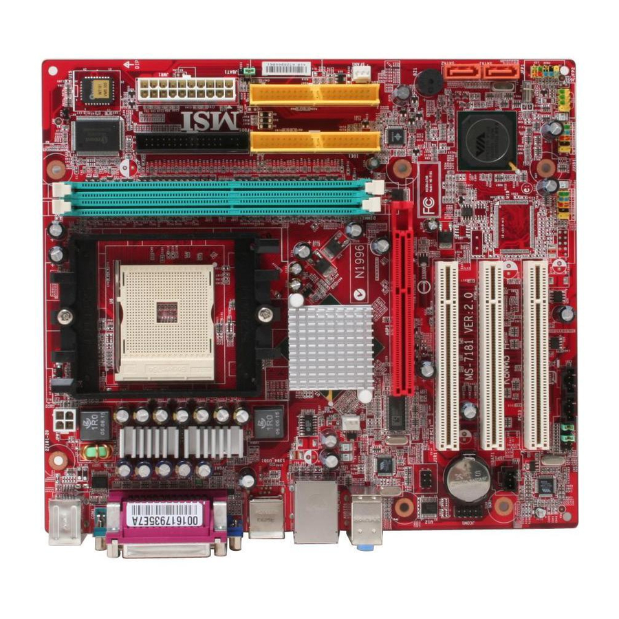
Page 15: Mainboard Layout
M S-7181 M icro-ATX M ainboard Mainboard Layout JCI1 DDR1 DDR2 Top : mouse Bottom: keyboard JPW1 BIOS Top : Parallel Port Bottom: COM Port VGA Port Top :1394 port B:USB ports Top: LAN Jack Bottom: USB ports K8M800 Line-In Line-Out CPUFAN1 B:Mic... -
Page 16: Packing Contents
Getting Started Packing Contents SATA RAID Driver MSI Driver/Utility CD Diskette MSI motherboard Flat Cable of SATA Cable/ Flat Cable of Floppy Disk Power Cable (Optional) IDE Devices 1394 Cable Back IO Shield User’s Guide (Optional) SPDIF-Bracket USB Bracket (Optional) -
Page 17: Chapter 2. Hardware Setup
Hardware Setup Chapter 2. Hardware Setup Hardware Setup This chapter provides you with the information about hardware setup procedures. W hile doing the installation, be careful in holding the com- ponents and follow the installation procedures. For some components, if you install in the wrong orientation, the components will not work properly. -
Page 18: Quick Components Guide
M S-7181 M icro-ATX M ainboard Quick Components Guide JCI1, p.2-18 JPW1, p.2-8 DIMM1-2, p.2-6 CPU, p.2-3 FDD1, p.2-14 JWR1, p.2-8 I/O Ports, p.2-9 JBAT1, p.2-21 IDE1, IDE2, p.2-15 SFAN1, p.2-14 CPUFAN1, p.2-14 AGP slot, p.2-22 JIR1, p.2-19 PCI slots, p.2-22 JCOM1, p.2-18 SATA1/2, p.2-16 JSP1, p.2-20... -
Page 19: Central Processing Unit: Cpu
Memory Speed/CPU FSB Support Matrix DDR 400 DDR 266 DDR 333 FSB 800 MSI Reminds You... Overheating Overheating will seriously damage the CPU and system, always make sure the cooling fan can work properly to protect the CPU from overheating. -
Page 20: Cpu Installation Procedures For Socket 754
M S-7181 M icro-ATX M ainboard CPU Installation Procedures for Socket 754 Please turn off the power and unplug the power cord before O pen Lever installing the CPU. Sl i di ng 90 degree Pl at e Pull the lever s ideways away from the socket. -
Page 21: Installing Amd Athlon64 Cpu Cooler Set
Fixed Bolt. Lift up the in- CPUFAN1 connector on the tensive fixed lever. board MSI Reminds You... While disconnecting the Safety Hook from the fixed bolt, it is necessary to keep an eye on S a f e t y... -
Page 22: Memory
The mainboard provides two slots for 184-pin DDR SDRAM DIMM (Double In-Line Memory Module) modules and supports up to 2GB memory size. You can install PC3200/DDR400, PC2700/DDR333 & PC2100/DDR266 modules on the DDR DIMM slots (DDR 1~2). For the updated supporting memory modules, please visit http://www.msi.com.tw/ program/products/mainboard/mbd/pro_mbd_trp_list.php. DDR DIMM Slots (DIMM1~2) -
Page 23: Ddr Dimm Module Combination
3. The plastic clip at each side of the DIMM slot will automatically close. Notch Volt MSI Reminds You... You can barely see the golden finger if the module is properly inserted in the socket. 2 - 7... -
Page 24: Power Supply
This 12V power connector is used to provide power to the CPU. SIGNAL JPW1 Pin Definition JPW1 MSI Reminds You... There is a mechanis m of this mainboard to protect it from being damaged. The power will shut down automatically in two conditions: the temperature of CPU reaches 100 C, or the low voltage occurs during booting up. -
Page 25: Back Panel
Hardware Setup Back Panel View of the Back Panel The back panel provides the following connectors: (optional) L-in 1394 Parallel Mouse Port Keyboard USB Ports USB Ports COM 1 VGA Port L-out Serial Port: COM1 The mainboard provides one 9-pin mail DIN connector as serial port COM1. The serial port is a 16550A high speed communication port that sends/receives 16 bytes FIFOs. -
Page 26: Mouse Connector
M S-7181 M icro-ATX M ainboard Mouse Connector ® The mainboard provides a standard PS/2 mouse mini DIN connector for attaching a ® ® PS/2 mouse. You can plug a PS/2 mouse directly into this connector. The connector location and pin assignments are as follows. Pin Definition SIGNAL DESCRIPTION... -
Page 27: Usb Ports
Hardware Setup USB Ports The mainboard provides a UHCI (Universal Host Controller Interface) Universal Serial Bus root for attaching USB devices such as keyboard, mouse or other USB-compat- ible devices. You can plug USB devices directly into the ports. Pin Definition SIGNAL DESCRIPTION 1 2 3 4... -
Page 28: Ieee1394 Port
CD player, Tape player, or other audio devices. Mic is a connector for microphones. Line In Line Out M IC MSI Reminds You... For advanced audio application, VIA VT1617 audio chip is provided to offer support for 6-channel audio operation and can turn rear audio connectors from 2-channel to 4-/6-channel audio. -
Page 29: Parallel Port
Hardware Setup Parallel Port The mainboard provides a 25-pin female centronic connector as LPT. A parallel port is a standard printer port that supports Enhanced Parallel Port (EPP) and Extended Capabilities Parallel Port (ECP) mode. Pin Definition SIGNAL DESCRIPTION STROBE Strobe DATA0 Data0... -
Page 30: Connectors
+12V Fan Connector SFAN1 CPUFAN1 Pin Definition MSI Reminds You... 1. Always consult the vendors for proper CPU cooling fan. 2. CPUFAN1 supports Smart Fan control, you may set up the smart fan control functions in the BIOS setup. 2-14... -
Page 31: Hard Disk Connectors: Ide1 & Ide2
(reserved for future BIOS), and other devices. IDE1 IDE2 MSI Reminds You... If you install two hard disks on cable, you must configure the second drive to Slave mode by setting its jumper. Refer to the hard disk documentation s upplied by hard disk vendors for jumper s etting instructions. -
Page 32: Serial Ata/Serial Ata Raid Connectors Controlled By Vt8237R/Vt8237R Plus: Sata1 & Sata2
Optional Serial ATA cable devices Connect to SATA1 or SATA2 MSI Reminds You... Please do not fold the serial ATA cable in a 90-degree angle, which will cause the loss of data during the transmission. 2-16... -
Page 33: Front Panel Connectors: Jfp1 & Jfp2
Hardware Setup Front Panel Connectors: JFP1 & JFP2 The mainboard provides two front panel connectors for electrical connection to the ® front panel switches and LEDs. JFP1 is compliant with Intel Front Panel I/O Connec- tivity Design Guide. Power Power JFP2 Power JFP1... -
Page 34: Aux Line-In Connector: Jaux1
Description USBPWR USBPWR USBP2- USBP3- JUSB1/JUSB2 USBP2+ USBP3+ OC # USB 2.0 Bracket Connected to JUSB1 (optional) or JUSB2 MSI Reminds You... Note that the pins of VCC and GND must be connected correctly, or itmay cause some damage. 2-18... -
Page 35: Front Panel Audio Connector: Jaud1
Left channel audio signal to front panel AUD_RET_L Left channel audio signal return from front panel MSI Reminds You... If you don’t want to connect to the front audio header, pins 5 & 6, 9 & 10 have to be jumpered in order to have signal output directed to the rear audio ports. -
Page 36: Ieee 1394 Connector: J1394_1
M S-7181 M icro-ATX M ainboard IEEE 1394 Connector: J1394_1 (optional) The mainboard provides one IEEE1394 pin header that allows you to connect IEEE 1394 port via an external IEEE1394 bracket (optional). Pin Definition SIGNAL SIGNAL J1394_1 TPA+ TPA- Ground Ground TPB+ TPB-... -
Page 37: Jumpers
JBAT1 Keep Data Clear Data MSI Reminds You... You can clear CMOS by shorting 2-3 pin while the system is off. Then return to 1-2 pin position. Avoid clearing the CMOS while the system is on; it will damage the mainboard. -
Page 38: Slots
M S-7181 M icro-ATX M ainboard Slots The motherboard provides one AGP slot and three 32-bit PCI bus slots. AGP (Accelerated Graphics Port) Slot The AGP slot allows you to insert the AGP graphics card. AGP is an interface speci- fication designed for the throughput demands of 3D graphics. -
Page 39: Chapter 3. Bios Setup
SETUP. ² You want to change the default settings for customized features. MSI Reminds You... 1. The items under each BIOS category described in this chapter are under c on tinuous update for better s y s tem per formanc e. -
Page 40: Entering Setup
M S-7181 M icro-ATX M ainboard Entering Setup Power on the computer and the system will start POST (Power On Self Test) process. W hen the message below appears on the screen, press <DEL> key to enter Setup. Press DEL to enter SETUP If the message disappears before you respond and you still wish to enter Setup, restart the system by turning it OFF and On or pressing the RESET button. -
Page 41: Control Keys
BIOS Setup Control Keys < > Move to the previous item < > Move to the next item < > Move to the item in the left hand < > Move to the item in the right hand <Enter> Select the item <Esc>... -
Page 42: The Main Menu
M S-7181 M icro-ATX M ainboard The Main Menu ® Once you enter Phoenix-Award BIOS CMOS Setup Utility, the Main Menu will appear on the screen. The Main Menu allows you to select from the eleven setup functions and two exit choices. Use arrow keys to select among the items and press <Enter> to accept or enter the sub-menu. - Page 43 BIOS Setup BIOS Setting Password Use this menu to set the password for BIOS. Save & Exit Setup Save changes to CMOS and exit setup. Exit Without Saving Abandon all changes and exit setup. 3 - 5...
-
Page 44: Standard Cmos Features
M S-7181 M icro-ATX M ainboard Standard CMOS Features The items in Standard CMOS Features Menu includes some basic setup items. Use the arrow keys to highlight the item and then use the <PgUp> or <PgDn> keys to select the value you want in each item. Date This allows you to set the system to the date that you want (usually the current date). - Page 45 BIOS Setup Drive A This item allows you to set the type of floppy drive installed. Available options: [None], [360K, 5.25 in.], [1.2M, 5.25 in.], [720K, 3.5 in.], [1.44M, 3.5 in.], [2.88M, 3.5 in.]. Halt On The setting determines whether the system will stop if an error is detected at boot. Available options are: [All Errors] The system stops when any error is detected.
-
Page 46: Advanced Bios Features
1st/2nd/3rd Boot Device The items allow you to set the sequence of boot devices where BIOS attempts to load the disk operating system. MSI Reminds You... Available settings for “1st/2nd/3rd Boot Device” vary depending on the bootable devices you have installed. - Page 47 BIOS Setup Hard Disk Boot Priority Press <Enter> to enter the sub-menu and the following screen appears: In the sub-menu, it shows the hard disks information that was installed in the system, and you can set the hard disk boot priority. IOAPIC Function This field is used to enable or disable the APIC (Advanced Programmable Interrupt Controller).
-
Page 48: Advanced Chipset Features
M S-7181 M icro-ATX M ainboard Advanced Chipset Features AGP & P2P Bridge Control Press <Enter> to enter the sub-menu and the following screen appears: AGP Aperture Size This setting controls just how much system RAM can be allocated to AGP for video purposes. - Page 49 BIOS Setup AGP Fast Write This option enables or disables the AGP Fast Write feature. The Fast Write technology allows the CPU to write directly to the graphics card without passing anything through the system memory and improves the AGP 4X speed. Select Enabled only when the installed AGP card supports this function.
- Page 50 M S-7181 M icro-ATX M ainboard Min RAS# Active Time (Tras) W hen the Timing Mode is set to [Manual], the field is adjustable. This setting determines the time RAS takes to read from and write to a memory cell. Setting options: [Auto], [5T~15T].
- Page 51 BIOS Setup PCI1/2 Master 0 WS Write W hen [Enabled], writes to the PCI bus are executed with zero wait states. Setting options: [Enabled], [Disabled]. PCI1/PCI2 Post Write You can enable or disable the ability of the chipset to use a buffer for posted writes initiated on the PCI bus.
-
Page 52: Integrated Peripherals
M S-7181 M icro-ATX M ainboard Integrated Peripherals AC97 Controller Select [Enabled] if you intend to use the onboard audio AC97 controller. Disable the controller if you want to use other controller cards to connect an audio device. Setting options: [Enabled], [Disabled]. Onboard LAN Control This setting controls the onboard Intel LAN controller. - Page 53 BIOS Setup IDE Devices Configuration Press <Enter> to enter the sub-menu and the following screen appears: OnChip SATA This setting controls the onchip SATA. Setting options: [Enabled], [Disabled]. SATA Mode This item specify the mode for SATA devices. Setting options: [RAID], [IDE]. IDE DM A transfer access Setting to [Enabled] will open DMA bus master and execute DMA action in DOS, which will make the data transferring faster.
- Page 54 M S-7181 M icro-ATX M ainboard UART Mode Select This setting allows you to specify the operation mode for serial port 2. Setting options: [IrDA], [ASKIR], [Normal]. Normal RS-232C Serial Port IrDA IrDA-compliant Serial Infrared Port ASKIR Amplitude Shift Keyed Infrared Port RxD, TxD Active This setting controls the receiving and transmitting speed of the IR peripheral in use.
-
Page 55: Power Management Setup
BIOS Setup Power Management Setup MSI Reminds You... S3-related functions described in this section are available only when your BIOS supports S3 sleep mode. ACPI Function This item is to activate the ACPI (Advanced Configuration and Power Management Interface) Function. If your operating system is ACPI-aware, such as W indows 2000/ XP, select [Enabled]. - Page 56 M S-7181 M icro-ATX M ainboard Suspend Time Out (M inute) If system activity is not detected for the length of time specified in this field, all devices except CPU will be shut off. Settings: [Disabled], [1], [2], [4], [8], [10], [20], [30], [40], [50], [60].
- Page 57 BIOS Setup Resume By PS/2 M ouse The setting determines whether the system will be awakened from what power saving modes when input signal of the PS/2 mouse is detected. Setting options: [Disabled], [Enabled]. Resume by PCI Device (PME#) W hen setting to [Enabled], this setting allows your system to be awakened from the power saving modes through any event on PME (Power Management Event).
-
Page 58: Pnp/Pci Configurations
M S-7181 M icro-ATX M ainboard PNP/PCI Configurations This section describes configuring the PCI bus system and PnP (Plug & Play) feature. PCI, or Peripheral Component Interconnect, is a system which allows I/O devices to operate at speeds nearing the speed the CPU itself uses when communicating with its special components. - Page 59 14/15 are allocated to the onboard PCI IDE, IRQ 9 will still be available for PCI and PnP devices. Available settings: [Reserved] and [Available]. MSI Reminds You... IRQ (Interrupt Request) lines are system resources allocated to I/O devices. When an I/O device needs to gain attention of the operating system, it signals this by causing an IRQ to occur.
-
Page 60: H/W Monitor
CPU’s from overheading due to the heavy working loading. Setting options: [Disabled], [Auto]. MSI Reminds You... 1. For the purpose of ensuring the stability of Cool'n'Quiet function, it is always recommended to have the memories plugged in DIMM1. - Page 61 BIOS Setup Chassis Intrusion The field enables or disables the feature of recording the chassis intrusion status and issuing a warning message if the chassis is once opened. To clear the warning message, set the field to [Reset]. The setting of the field will automatically return to [Enabled] later.
-
Page 62: Load Optimized Defaults
M S-7181 M icro-ATX M ainboard Load Optimized Defaults The option on the main menu allows users to restore all of the BIOS settings to the Optimized values. The Optimized Defaults are the default values set by the mainboard manufacturer specifically for optimal performance of the mainboard. W hen you select Load Optimized Defaults, a message as below appears: Pressing Y loads the default factory settings for optimal system performance. -
Page 63: Bios Setting Password
BIOS Setup BIOS Setting Password W hen you select this function, a message as below will appear on the screen: Type the password, up to eight characters in length, and press <Enter>. The pass- word typed now will replace any previously set password from CMOS memory. You will be prompted to confirm the password. -
Page 64: Chapter 4. Introduction To Digicell
MP3 files management and communication / 802.11g W LAN settings. Moreover, with this unique utility, you will be able to activate the MSI well-known features, Live Update and PC Alert, which makes it easier to update the BIOS/drivers online, and to monitor the system hardware status (CPU/Fan temperature and speed). -
Page 65: Main
Introduction: Click on each icon appearing above to enter the sub-menu to make further configuration. M SI Click on this button to link to MSI website: http://www.msi.com.tw. Quick Guide Click on this button and the quick guide of DigiCell will be displayed for you to review. - Page 66 Power on Agent In this sub-menu, you can configure date, time and auto-executed programs of the power-on, power-off and restarting features. MSI Reminds You... Click on back button in every sub-menu and it will bring you back to the main menu.
-
Page 67: H/W Diagnostic
DigiCell. You may double check the connection and installation of the item marked as gray. You may also click on the Mail to MSI button to send your questions or suggestions to MSI’s technical support staff. 4 - 4... -
Page 68: Communication
Introduction to DigiCell Communication In the Communication sub-menu, you can see the status of all the LAN / W LAN / Bluetooth on the screen if the hardware is installed. The first icon indicates the onboard LAN on your system, the second icon indicates the wireless LAN status, and the third one is the information about the bluetooth on your system. -
Page 69: Software Access Point
M S-7181 M icro-ATX M ainboard M SI Feature Software Access Point In the Software Access Point sub-menu, you can see the communication status on your system and choose the desired software access point mode by clicking on the desired icon, in which the default settings are configured for your usage. The default software access point mode is set to WLAN Card M ode. -
Page 70: Access Point Mode
Introduction to DigiCell Access Point Mode Click on “Setting” button of the Access Point Mode and the following screen will display. IP Sharing Click on this icon to enable/disable the IP sharing. The default of this setting is disabled. Disabled. Enabled. -
Page 71: Wlan Card Mode
M S-7181 M icro-ATX M ainboard M SI Feature Association Control This option allows you to control which PC can connect to the wireless LAN. If you enable this feature, only PCs with MAC address located in Association Control List can connect to the wireless LAN. -
Page 72: Live Update
BIOS/VGA Driver/Utility online so that you don’t need to search for the correct BIOS/driver version throughout the whole W eb site. To use the function, you need to install the “MSI Live Update 3” application. After the installation, the “MSI Live Update 3”... -
Page 73: Mega Stick
M S-7181 M icro-ATX M ainboard M SI Feature MEGA STICK In the MEGA STICK sub-menu, you can configure the settings of MSI MEGA STICK and the media files (*.m3u, *.mp3, *.wav, *.cda, *.wma) on your system. Basic Function Here you can edit your own play list with the buttons “load”, “save”, “delete”, “shuttle”, “repeat”... - Page 74 Introduction to DigiCell There is also a toolbar for you to execute some basic function, like play, stop, pause, previous/next song, song info and volume adjust. There is also a scroll bar on the top for you to forward/rewind. pause previous next forward/rewind...
-
Page 75: Non-Unicode Programs Supported
M S-7181 M icro-ATX M ainboard M SI Feature Non-Unicode programs supported If you are using an operating system in European languages, and you’d like to play the media files in MEGA STICK with East-Asian languages (such as Chinese, Japanese... etc.), it is possible that the file names display incorrectly. - Page 76 Introduction to DigiCell 3. Then go to the [Advanced] tab and select the language you want to be supported (the language of the filename in the MegaStick) from the drop- down list in the [Language for non-Unicode programs], then click [Apply]. The system will install the necessary components from your Microsoft Setup CD immediately.
-
Page 77: Pc Alert
M S-7181 M icro-ATX M ainboard M SI Feature PC Alert Click on the PC Alert icon in the main menu and the PC Alert program will be enabled. PC Alert is just like your PC doctor that can detect and view the PC hardware and system status during real time operation. -
Page 78: Audio Speaker Setting
Introduction to DigiCell Audio Speaker Setting In the Audio Speaker Setting sub-menu, you can configure the multi-channel audio operation, perform speaker test, and choose the environment you prefer while en- joying the music. You can scroll the bar of each equalizer to regulate the current playing digital sound source. - Page 79 M S-7181 M icro-ATX M ainboard M SI Feature Click on the “Speaker test” button and the following screen will appear: Center Front Right Front Left Rear Left Rear Right Subwoofer In this Speaker Test dialogue box, first select the correct item from the Speaker mode drop-down list, and then click on eac h connected speaker to ensure if Headphone, 2-, 4-, or 5.1- channel audio operation is working properly.
-
Page 80: Power On Agent
Click “OK” to restart the computer right away or click “Later” to restart your computer later. MSI Reminds You... Please note that the new setting will not take effect until you restart your computer. -
Page 81: Power Off / Restart
Delete. delete the added program MSI Reminds You... You can also enable the Every turn on function, which will enable the specified program(s) and file(s) every time the Digi Cell utility runs. -
Page 82: Auto Login
Introduction to DigiCell Auto Login Since the Power On function allows the system to power on automatically, you may have to enable this Auto Login function in the following situations: 1. If you are using a computer belonging to a domain in office, and you need to enter your user name &... -
Page 83: Chapter 5. Via Vt8237R/ Vt8237R Plus Sata Raid Introduction
VIA VT8237R/Plus Serial ATA RAID Introduction Chapter 4. Introduction to Chapter 2. Hardware Setup Appendix. Using 4- or 6-Channel DigiCell Audio Function VIA VT8237R/ VT8237R Plus SATA RAID Introduction Appendix. Using 4- or 6-Channel The Southbridge VT8237R/ VT8237R Plus provides a hybrid solution that combines two independent SATA ports for support of up to two Serial ATA (Serial ATA RAID) drives. -
Page 84: Introduction
M S-7181 M icro-ATX M ainboard Introduction This section gives a brief introduction on the RAID-related background knowledge and a brief introduction on VIA SATA RAID Host Controller. For users wishing to install their VIA SATA RAID driver and RAID software, proceed to Driver and RAID Soft- ware Installation section. -
Page 85: Bios Configuration
VIA VT8237R/Plus Serial ATA RAID Introduction BIOS Configuration W hen the system powers on during the POST (Power-On Self Test) process, press <Tab> key to enter the BIOS configuration. The Serial ATA RAID volume may be configured using the VIA Tech. RAID BIOS. Always use the arrow keys to navigate the main menu, use up and down arrow key to select the each item and press <Enter>... -
Page 86: Create Disk Array
Create Disk Array Use the up and down arrow keys to select the Create Array command and press <Enter>. MSI Reminds You... The “Channel”, “Drive Name”, “Mode” and “Size (GB)” in the following example might be different from your system. - Page 87 VIA VT8237R/Plus Serial ATA RAID Introduction After array mode is selected, there are two methods to create a disk array. One method is “Auto Setup” and the other one is “Select Disk Drives”. Auto Setup allows BIOS to select the disk drives and create arrays automatically, but it does not duplicate the mirroring drives even if the user selected Create and duplicate for RAID 1.
-
Page 88: Delete Disk Array
M S-7181 M icro-ATX M ainboard MSI Reminds You... Even though 64KB is the recommended setting for most users, you should choose the block size value which is best suited to your specific RAID usage model. 4KB: For specialized usage models requiring 4KB blocks... -
Page 89: Create And Delete Spare Hard Drive
VIA VT8237R/Plus Serial ATA RAID Introduction Create and Delete Spare Hard Drive If a RAID 1 array is created and there are drives that do not belong to other arrays, the one that has a capacity which is equal to or greater than the array capacity can be selected as a spare drive for the RAID 1 array. -
Page 90: Duplicate Critical Raid 1 Array
M S-7181 M icro-ATX M ainboard Duplicate Critical RAID 1 Array W hen booting up the system, BIOS will detect if the RAID 1 array has any inconsis- tencies between user data and backup data. If BIOS detects any inconsistencies, the status of the disk array will be marked as critical, and BIOS will prompt the user to duplicate the RAID 1 in order to ensure the backup data consistency with the user data. - Page 91 VIA VT8237R/Plus Serial ATA RAID Introduction 1. Power off and Check the Failed Drive: This item turns off the computer and replaces the failed hard drive with a good one. If your computer does not support APM, you must turn off your computer manually. After replacing the hard drive, boot into BIOS and select Choose replacement drive and rebuild to rebuild the broken array.
-
Page 92: Installing Raid Software & Drivers
Please follow the instruction below to make a VIA Serial ATA RAID driver for yourself. 1. Insert the MSI CD into the CD-ROM drive. 2. Ignore the Setup screen and use “Explorer” to browse the 3. C op y a ll t h e c o n te nt s ( in c lu din g th e s ub - fo ld e rs ) in th e \\IDE\VIA\Floppy to a fomatted floppy disk. -
Page 93: Installation Of Via Sata Raid Drvier And Utility
† VIA SATA RAID utility † RAID0 and RAID1 functions Insert the MSI CD and click on the VIA SATA/IDE RAID Drivers to install the software. The InstallShield Wizard will begin automatically for installation. Click on the Next button to proceed the installation in the welcoming window. - Page 94 M S-7181 M icro-ATX M ainboard Put a check mark in the check box to install the feature you want. Then click Next button to proceed the installation. Finally, click “Finish” to complete the installation. 5-12...
-
Page 95: Using Via Raid Tool
VIA VT8237R/Plus Serial ATA RAID Introduction Using VIA RAID Tool Once the installation is complete, go to Start ---> Programs --->VIA ---> RAID ---> raid_tool.exe to enable VIA RAID Tool. After the software is finished installation, it will automati- cally started every time W indows is initiated. You may double-click on the icon shown in the system tray of the tool bar to launch the VIA RAID Tool utility. - Page 96 M S-7181 M icro-ATX M ainboard Cl ic k on button to determine the viewing type of left window pane. There are two viewing types: By controllers and by device. Click on the object in the left window pane to display the status of the object in the right windowpane. The following screen shows the status of Array 0---RAID 0.
- Page 97 VIA VT8237R/Plus Serial ATA RAID Introduction You may also use the same button to view the statuses of Array 0- --RAID 1. Click on the plus (+) symbol next to Array 0---RAID 1 to see the details of each disk. 5-15...
-
Page 98: Chapter 6. Using 2-, 4- & 6-Channel Audio Function
Using 2-, 4- & 6-Channel Audio Function Chapter 5. Intel ICH6R RAID Introduc- tion Using 2-, 4- & 6-Channel Audio Function The mainboard is equipped with VIA VT1617A chip, which provides support for 6-channel audio output, including 2 Front, 2 Rear, 1 Center and 1 Subwoofer channel. -
Page 99: Installing The Audio Driver
M S-7181 M icro-ATX M ainboard Installing the Audio Driver You need to install the driver for VIA VT1617 chip to function properly before you can get access to 4-/6-channel audio operations. Follow the procedures described below to install the drivers for different operating systems. Installation for Windows 98SE/ME/2000/XP ®... - Page 100 Using 2-, 4- & 6-Channel Audio Function 3. Click Next to install the AC’97 Audio software, and click Finish to restart the system. 4. You will find the icon in the system tray and on the desktop. Double-click the icon on the desktop or right-click on the icon in the system tray. Also, you can right- click on the icon in the system tray and choose VIA Audio Deck, and the following screen will appear to show some basic settings about the audio configuration.
-
Page 101: Software Configuration
M S-7181 M icro-ATX M ainboard Software Configuration After installing the audio driver, you are able to use the 4-/6-channel audio feature now. Click the audio icon from the window tray at the lower-right corner of the screen to activate the VIA Audio Deck Configuration. Speaker Here you can select the channels you would like to use here. -
Page 102: Mixer
Using 2-, 4- & 6-Channel Audio Function Mixer In the Mixer part, you may adjust the volumes individually. Playback Here you can regulate the volume of each output. Click the allow button to the right for more outputs. Recording Here you can choose the preferred recording input. Choosing M ic allows you to record the audio through the connected microphones, Line In allows you to record to record through the connected line-in device, and etc. -
Page 103: Spdif
M S-7181 M icro-ATX M ainboard SPDIF Here you can configure and enable the functions related to S/PDIF. Move between the items in S/PDIF Control and Advanced control and the representing description and illustrations will display. If you’d like to use the S/PDIF function for digital audio transmission, please check the S/PDIF Enable and/or Analog in to S/PDIF Out check boxes as wished. -
Page 104: Information
Using 2-, 4- & 6-Channel Audio Function Information Here it provides the information about Vinyl Deck, including the driver version, codec type, and OS version... etc. 6 - 7... -
Page 105: Using 2-, 4- & 6- Channel Audio Function
M S-7181 M icro-ATX M ainboard Using 2-, 4- & 6- Channel Audio Function Connecting the Speakers W hen you have set the Multi-Channel Audio Function mode properly in the software utility, connect your speakers to the correct phone jacks in accordance with the setting in software utility. - Page 106 Using 2-, 4- & 6-Channel Audio Function n 4-Channel M ode for 4-Speaker Output The audio jacks on the back panel always provide 2-channel analog audio output function, however these audio jacks can be transformed to 4- or 6- channel analog audio jacks by selecting the corresponding multi-channel operation from No.
- Page 107 Line Out function when 6-Channel Mode for 6-Speaker Output is selected. MSI Reminds You... If the audio signals coming from the Center and Subwoofer speaker are swapped when you play video or music on the computer, a con- verter may be required to exchange center and subwoofer audio signals.
Need help?
Do you have a question about the K8MM3 Series and is the answer not in the manual?
Questions and answers