MSI 915GM User Manual
Micro-atx mainboard
Hide thumbs
Also See for 915GM:
- User manual (95 pages) ,
- User manual (98 pages) ,
- User manual (94 pages)
Table of Contents
Advertisement
Advertisement
Table of Contents

Related Manuals for MSI 915GM


Summary of Contents for MSI 915GM
- Page 1 915GM6/PM6/GVM6 Series MS-7177 (v2.X) Micro-ATX Mainboard G52-M7177X1...
-
Page 2: Fcc-B Radio Frequency Interference Statement
Manual Rev: 2.0 Release Date: Aug. 2005 FCC-B Radio Frequency Interference Statement This equipment has been tested and found to comply with the limits for a class B digital device, pursuant to part 15 of the FCC rules. These limits are designed to provide reasonable protection against harmful interference in a residential installation. -
Page 3: Revision History
This device complies with Part 15 of the FCC Rules. Operation is subject to the following two conditions: (1) this device may not cause harmful interference, and (2) this device must accept any interference received, including interference that may cause undesired operation Copyright Notice T he material in this document is the intellec tual property of M ICRO-STAR INTERNATIONAL. -
Page 4: Technical Support
Alternatively, please try the following help resources for further guidance. † Visit the MSI homepage & FAQ site for technical guide, BIOS updates, driver updates, and other information: http://www.msi.com.tw & http://www.msi. -
Page 5: Weee Statement
WEEE Statement... -
Page 8: Table Of Contents
CONTENTS FCC-B Radio Frequency Interference Statement ... ii Copyright Notice ... iii Technical Support ... iv Safety Instructions ... iv WEEE Statement ... v Chapter 1. Getting Started ... 1-1 Mainboard Specifications ... 1-2 Mainboard Layout ... 1-4 Chapter 2. Hardware Setup ... 2-1 Quick Components Guide ... - Page 9 FWH/LPC Debugging Pin Header: JLPC1 ... 2-19 W ake On LAN Connector: WOL ... 2-19 Chassis Intrusion Switch Connector: JC1 ... 2-19 Front USB Connectors: F_USB1/ F_USB2 ... 2-20 Front Panel Audio Connector: F_AUD ... 2-20 Jumpers ... 2-21 Clear CMOS Jumper: CLR_CMOS ... 2-21 Slots ...
- Page 10 MEGA STICK ... 4-10 Basic Function ... 4-10 Non-Unicode programs supported ... 4-12 Core Center (for Pentium 4 CPU) ... 4-14 Left-wing: Current system status ... 4-15 Right-wing: PC hardware status during real time operation ... 4-15 Audio Speaker Setting ... 4-16 Power on Agent ...
-
Page 11: Chapter 1. Getting Started
Chap t er 1 . Ge tting Started Getting Started Thank you for choosing the 915GM6/ PM6/ GVM6 Series (MS-7177) v2.x M-ATX mainboard. The 915GM6/ PM6/ GVM6 Se- ries mainboard is based on Intel for optimal system efficiency. Designed to fit the advanced Intel Pentium 4 Prescott LGA775 processor, the 915GM6/ PM6/ GVM6 Series mainboard delivers a high performance and professional desktop platform solution. -
Page 12: Mainboard Specifications
Pentium 4 Prescott LGA775 processors in LGA775 package. † Supports up to Pentium 4 3XX, 5XX & P4EE (Intel Pentium 4 Processor with HT Technology Extreme Edition) . (For the latest information about CPU, please visit http://www.msi.com.tw/program/ products/mainboard/mbd/pro_mbd_cpu_support.php) Chipset † Intel ®... - Page 13 On-Board Peripherals † On-Board Peripherals include: - 1 floppy port supports 1 FDD with 360K, 720K, 1.2M, 1.44M and 2.88Mbytes - 2 serial ports (Real *1/ Front *1) - 1 VGA port (for 915G/915GV only, Optional) - 1 parallel port supports SPP/EPP/ECP mode - 1 Line-In / Line-Out / MIC-In 3 in 1 audio connector - 8 USB ports (Rear * 4/ Front * 4) - 1 RJ-45 LAN jack...
-
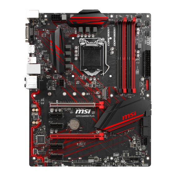
Page 14: Mainboard Layout
M S-7177 M -ATX M ainboard Mainboard Layout T: mo use B: key board SYS_FAN L ine-In Line-Out B:Mi c PCI-E1 (optional) PCI1 CHIP PCI 2 PCI3 ALC6 55 CD _IN AUX_ IN1 F_AUD 915GM6/ 915PM6/ 915GVM6 Series (MS-7177) v2.x M-ATX Mainboard Winbond W83627THF CPU_FAN... -
Page 15: Chapter 2. Hardware Setup
Chapter 2. Hardware Setup Hardware Setup This chapter tells you how to install the CPU, memory modules, and expansion cards, as well as how to setup the jumpers on the mainboard. Also, it provides the instructions on connecting the periph- eral devices, such as the mouse, keyboard, etc. -
Page 16: Quick Components Guide
M S-7177 M -ATX M ainboard Quick Components Guide SYS_FAN, p.2-15 JPW1, p.2-9 Back Panel I/O, p.2-10 PCI Express x16, p.2-22 PCI Slots 1~3, p.2-22 F_AUD,p.2-20 CD_IN, p.2-16 AUX_IN, p.2-16 WOL, p.2-19 DDR DIMMs, p.2-7 CPU_FAN, p.2-15 JFP1, p.2-18 COM2, p.2-21 CLR_CMOS1, p.2-21 F_USB1, F_USB2... -
Page 17: Central Processing Unit: Cpu
If you do not have the CPU cooler, contact your dealer to purchase and install them before turning on the computer. For the latest information about CPU, please visit http://www.msi.com.tw/ program/products/mainboard/mbd/pro_mbd_cpu_support.php. MSI Reminds You... -
Page 18: Cpu & Cooler Installation
3. Use 2 hands to remove the land side cover (if any). Please note not to touch the pins. MSI Reminds You... 1. Confirm if your CPU cooler is firmly installed before turning on your system. 2. Do not touch the CPU socket pins to avoid damaging. - Page 19 5. The CPU has a plastic cap on it to protect the contact from damage. Before you have installed the CPU, always cover it to protect the socket pin. 7. Lift the load lever up and open the load plate. 9.
- Page 20 15. Turn over the mainboard to confirm that th e c li p-en ds are c orrec tly inserted. MSI Reminds You... 1. Check the information in PC Health Status in BIOS (Chapter 3) for the CPU temperature. 2. Whenever CPU is not installed, always protect your CPU socket pin with the plastic cap covered (shown in Figure 1) to avoid damaging.
-
Page 21: Memory
DDR2 memory module in the DDR2 slot (DIMM1~DIMM4). Otherwise, you are not able to boot up your system and your mainboard might be damaged. For the updated supporting memory modules, please visit http://www.msi. com.tw/program/products/mainboard/mbd/pro_mbd_trp_list.php. Introduction to DDR2 SDRAM DDR2 is a new technology of memory module, and its speed is the top limit of current DDR1 technology. -
Page 22: Memory Module Population Rules
The plastic clip at each side of the DIMM slot will automatically close. Volt MSI Reminds You... You can barely see the golden finger if the module is properly in- serted in the socket. -
Page 23: Power Supply
ATX 12V Power Connector: JPW1 This 12V power connector is used to provide power to the CPU. JPW1 MSI Reminds You... 1. These two connectors connect to the ATX power supply and have to work together to ensure stable operation of the mainboard. -
Page 24: Back Panel
M S-7177 M -ATX M ainboard Back Panel The back panel provides the following connectors: Parallel M ou se COM1 Keyboard (for 915G/GV) Mouse/Keyboard Connector The mainboard provides a standard PS/2 ® for attaching a PS/2 mouse/keyboard. You can plug a PS/2 into this connector. -
Page 25: Serial Port Connector: Com1 & Com2
Serial Port Connector: COM1 & COM2 The mainboard offers one 9-pin male DIN connector COM A, and one optional serial header COM2. Both are 16550A high speed communication ports that send/ receive/ 16 bytes FIFOs. You can attach a serial mouse or other serial device directly to them. -
Page 26: Lan(Rj-45)Jack:10/100 Lan(8100C)/Giga-Bit Lan(8110S Is Optional)
M S-7177 M -ATX M ainboard LAN (RJ-45) Jack:10/100 LAN (8100C) /Giga-bit LAN (8110S is optional) The mainboard provides 1 standard RJ-45 jack for connection to single Local Area Network (LAN). This LAN enables data to be transferred at 10/ 100Mbps or (1000Mbps ->... -
Page 27: Audio Port Connectors
5.1-channel audio operation and can turn rear audio connectors from 2-channel to 4-/5.1- channel audio. MSI Reminds You... For the advanced functions of the audio codec, please refer to Chapter 4: Introduction to Realtek ALC655 Audio Codec for details. -
Page 28: Parallel Port Connector: Lpt1
M S-7177 M -ATX M ainboard Parallel Port Connector: LPT1 The mainboard provides a 25-pin female centronic connector as LPT. A parallel port is a standard printer port that supports Enhanced Parallel Port (EPP) and Ex- tended Capabilities Parallel Port (ECP) mode. SIGNAL STROBE DATA0... -
Page 29: Connectors
Control SENSOR +12V CPU_ FAN MSI Reminds You... 1. Always consult the vendors for proper CPU cooling fan. 2. CPU_FAN supports the fan control. Fan/heatsink with 3 or 4 fins are both available. 3. Please refer to the recommended CPU fans at Intel website. -
Page 30: Hard Disk Connector: Ide
IDE1 can connect a Master and a Slave drive. You must configure second hard drive to Slave mode by setting the jumper accordingly. MSI Reminds You... If you install two hard disks on cable, you must configure the second drive to Slave mode by setting its jumper. Refer to the hard disk documentation supplied by hard disk vendors for jumper setting instructions. -
Page 31: Serial Ata Connectors Controlled By Intel Ich6: Sata1~Sata4
SATA1 SATA2 Serial ATA cable Connect to serial ATA ports MSI Reminds You... Please do not fold the serial ATA cable in a 90-degree angle, since this might cause the loss of data during the transmission. Hardware Setup SATA1~ SATA4 Pin Definition... -
Page 32: Front Panel Connectors: Jfp1 & Jfp2
M S-7177 M -ATX M ainboard Front Panel Connectors: JFP1 & JFP2 The mainboard provides two front panel connectors for electrical connection to the front panel switches and LEDs. JFP1 is compliant with Intel Connectivity Design Guide. Speaker JFP2 Power LED JFP1 Pin Definition SIGNAL HD_LED_P... -
Page 33: Fwh/Lpc Debugging Pin Header: Jlpc1
You can wake up the computer via remote control through a local area network. MSI Reminds You... To be able to use this function, you need a power supply that provides enough power for this feature. (750 mA 5V Stand-by) Chassis Intrusion Switch Connector: JC1 This connector is connected to a 2-pin chassis switch. -
Page 34: Front Usb Connectors: F_Usb1/ F_Usb2
USB interface peripherals such as USB HDD, digital cameras, MP3 players, printers, modems and the like. F_USB1/ F_USB2 MSI Reminds You... Note that the pins of VCC and GND must be connected correctly, or it may cause some damage. -
Page 35: Jumpers
Jumpers The motherboard provides the following jumpers for you to set the computer’s function. This section will explain how to change your motherboard’s function through the use of jumpers. Clear CMOS Jumper: CLR_CMOS There is a CMOS RAM on board that has a power supply from external battery to keep the system configuration data. -
Page 36: Slots
M S-7177 M -ATX M ainboard The mainboard provides one PCI Express x16 slot and three 32-bit PCI bus slots. PCI Express Slot (optional) The PCI Express slot, as a high-bandwidth, low pin count, serial, intercon- nect technology, support Intel highest performance desktop platforms utilizing the Intel Pentium 4 processor with HT Technology. -
Page 37: Pci Interrupt Request Routing
PCI Interrupt Request Routing The IRQ, acronym of interrupt request line and pronounced I-R-Q, are hard- ware lines over which devices can send interrupt signals to the microprocessor. The PCI IRQ pins are typically connected to the PCI bus INT A# ~ INT D# pins as follows: Order 1 PCI Slot 1 INT A#... -
Page 38: Chapter 3. Bios Setup
SETUP. ² You want to change the default settings for customized features. MSI Reminds You... 1. The items under each BIOS category described in this chapter are under c ontinuous update for better s y s tem performanc e. -
Page 39: Entering Setup
The preset Optimal Defaults of the BIOS setup program provide optimal performance settings for all devices and the system. MSI Reminds You... The items under each BIOS category described in this chapter are under continuous update for better system performance. Therefore, the description may be slightly different from the latest BIOS and should be held for reference only. -
Page 40: The Main Menu
BIOS Setup The Main Menu Once you enter AwardBIOS CMOS Setup Utility, the Main Menu will appear on the screen. Use arrow keys to move among the items and press <Enter> to enter the sub-menu. Standard CMOS Features Use this menu for basic system configurations, such as time, date etc. Advanced BIOS Features ®... - Page 41 M S-7177 M -ATX M ainboard Load Fail-Safe Defaults Use this menu to load the default values set by the BIOS vendor for stable system performance. Load Optimized Defaults Use this menu to load the default values set by the mainboard manufacturer specifi- cally for optimal performance of the mainboard.
-
Page 42: Standard Cmos Features
Standard CMOS Features The items in Standard CMOS Features Menu includes some basic setup items. Use the arrow keys to highlight the item and then use the <+> or <-> keys to select the value you want in each item. Date (MM:DD:YY) This allows you to set the system to the date that you want (usually the current date). - Page 43 M S-7177 M -ATX M ainboard Primary IDE Master Press PgUp/<+> or PgDn/<-> to select [Manual], [None] or [Auto] type. Note that the specifications of your drive must match with the drive table. The hard disk will not work properly if you enter improper information for this category. If your hard disk drive type is not matched or listed, you can use [Manual] to define your own drive type manually.
-
Page 44: Advanced Bios Features
The items allow you to set the sequence of boot devices where BIOS attempts to load the disk operating system. MSI Reminds You... Available settings for “1st/2nd/3rd Boot Device” vary depending on the bootable devices you have installed. For example, if you did not install a floppy drive, the setting “Floppy”... - Page 45 M S-7177 M -ATX M ainboard CPU Feature Press <Enter> to enter the sub-menu and the following screen appears: Delay Prior to Thermal W hen the CPU temperature reaches a factory preset level, a thermal monitoring mechanism will be enabled following the appropriate timing delay specified in this field.
- Page 46 MSI Reminds You... Enabling the functionality of Hyper-Threading Technology for your com- puter system requires ALL of the following platform Components: ® * CPU: An Intel Pentium ® * Chipset: An Intel Chipset that supports HT Technology; * BIOS: A BIOS that supports HT Technology and has it enabled;...
- Page 47 M S-7177 M -ATX M ainboard Typematic Delay (Msec) This item allows you to select the delay between when the key was first pressed and when the acceleration begins. Settings: [250], [500], [750] and [1000]. Security Option This specifies the type of BIOS password protection that is implemented. Settings are described below: Option Description...
- Page 48 Report No FDD for WIN 95 For compatibility with W indows 95 logo certification, select Yes to release IRQ6 when the system contains no floppy drive. W hen this setting is set to Yes, users have to select Disabled for the Onboard FDC Controller in the Integrated Peripherals menu. Setting options: [No], [Yes].
-
Page 49: Advanced Chipset Features
M S-7177 M -ATX M ainboard Advanced Chipset Features MSI Reminds You... Change these settings only if you are familiar with the chipset. DRAM Timing Selectable Selects whether DRAM timing is controlled by the SPD (Serial Presence Detect) EEPROM on the DRAM module. Setting to [By SPD] enables DRAM timings and the following related items to be determined by BIOS based on the configurations on the SPD. - Page 50 Precharge delay (tRAS) This setting determines the precharge delay, which determines the timing delay for DRAM precharge. Setting options: [Auto], [4], [5], [6], [7], [8], [9], [10], [11], [12], [13], [14], [15]. M emory Frequency For User can place an artificial memory clock limit on the system. Please note that memory is prevented from running faster than this frequency.
- Page 51 M S-7177 M -ATX M ainboard DVM T Version This field shows the current DVMT (Dynamic Video Memory Technology) version. FIXED M emory Size This field specifies the size of system memory to allocate for video memory. Setting options: [64MB], [128MB]. Boot Display Use the field to select the type of device you want to use as the display(s) of the system.
-
Page 52: Integrated Peripherals
BIOS Setup Integrated Peripherals USB Controller This setting is used to enable/disable the onboard USB host controller. Setting options: [Disabled], [Enabled]. USB 2.0 Controller Set to [Enabled] if you need to use any USB 2.0 device in the operating system that does not support or have any USB 2.0 driver installed, such as DOS and SCO Unix. - Page 53 M S-7177 M -ATX M ainboard Onboard Lan Boot ROM This item is used to decide whether to invoke the Boot ROM of the Onboard LAN Chip. Settings: [Enabled], [Disabled]. SuperIO Device Press <Enter> to enter the sub-menu and the following screen appears: POWER ON Function This controls how the PS/2 mouse or keyboard can power on the system.
- Page 54 UR2 Duplex Mode This setting controls the operating mode of IR transmission/reception. Setting options: [Full], [Half]]. Under [Full] Duplex mode, synchronous, bi-directional trans- mission/ reception is allowed. Under [Half] Duplex mode, only asynchronous, bi- directional transmission/reception is allowed. Use IR Pin Please consult your IR peripheral documentation to select the correct setting of the TxD and RxD signals.
- Page 55 M S-7177 M -ATX M ainboard IDE Devices Configuration Press <Enter> to enter the sub-menu and the following screen appears: IDE HDD Block Mode Block mode is also called block transfer, multiple commands, or multiple sector read/write. If your IDE hard drive supports block mode (most new drives do), select [Enabled] for automatic detection of the optimal number of block read/ writes per sector the drive can support.
- Page 56 ***On-Chip Serial ATA Setting*** OnChip Serial ATA Mode [Disabled] Select this if you want to disable both SATA controller. [Combined] You can use the IDE, S-ATA and P-ATA devices, and maximum of 2 devices in each channel are supported (maxinum of 4 devices).
-
Page 57: Power Management Features
M S-7177 M -ATX M ainboard Power Management Features MSI Reminds You... S3-related functions described in this section are available only when your BIOS supports S3 sleep mode. ACPI Function This item is to activate the ACPI (Advanced Configuration and Power Management Interface) Function. - Page 58 Re-Call VGA BIOS from S3 W hen ACPI Standby State is set to [S3/STR], users can select the options in this field. Selecting [Yes] allows BIOS to call VGABIOS to initialize the VGA card when system wakes up (resumes) from S3 sleep state. The system resume time is short- ened when you disable the function, but system will need an AGP driver to initialize the VGA card.
- Page 59 M S-7177 M -ATX M ainboard Soft-Off by PWR-BTTN This feature allows users to configure the Power Button function. Settings are: [Instant-Off] The power button functions as a normal power-on/-off button. [Delay 4 Sec.] W hen you press the power button, the computer enters the suspend/sleep mode, but if the button is pressed for more than four seconds, the computer is turned off.
- Page 60 BIOS Setup USB KB Wake-Up From S3 The item allows the activity of the USB device to wake up the system from S3 (Suspend to RAM) sleep state. Setting options: [Disabled], [Enabled]. Resume by RTC Alarm This is used to enable or disable the feature of booting up the system on a scheduled time/date from the S3, S4, and S5 power off state.
-
Page 61: Pnp/Pci Configurations
M S-7177 M -ATX M ainboard PNP/PCI Configurations This section describes configuring the PCI bus system and PnP (Plug & Play) feature. PCI, or Peripheral Component Interconnect, is a system which allows I/O devices to operate at speeds nearing the speed the CPU itself uses when communicating with its special components. - Page 62 and the following sub-menu appears. IRQ 3/4/5/7/9/10/11/14/15 assigned to The items are adjustable only when Resources Controlled By is set to [Manual]. Press <Enter> and you will enter the sub-menu of the items. IRQ Resources list IRQ 3/4/5/7/9/10/11/12/14/15 for users to set each IRQ a type depending on the type of device using the IRQ.
- Page 63 M S-7177 M -ATX M ainboard PCI Slot1 IRQ, PCI Slot2 IRQ, PCI Slot3 IRQ These items specify the IRQ line for each PCI slot. Setting options: [3], [4], [5], [7], [9], [10], [11], [12], [14], [15], [Auto]. Selecting [Auto] allows BIOS to automatically deter- mine the IRQ line for each PCI slot.
-
Page 64: Pc Health Status
BIOS Setup PC Health Status This section shows the status of your CPU, fan, overall system status, etc. Monitor function is available only if there is hardware monitoring mechanism onboard. CPU Warning Temperature This item is used to specify a thermal limit for CPU. If CPU temperature reaches the specified limit, the system will issue a warning and allows you to prevent the CPU overheating problem. -
Page 65: Frequency/Voltage Control
(EMI). Setting options: [Enabled], [Disabled]. Spread Spectrum W hen the motherboard’s clock generator pulses, the extreme values (spikes) of the pulses creates EMI (Electromagnetic Interference). The Spread Spectrum function reduces the EMI generated by modulating the pulses so that the spikes of the pulses are reduced to flatter curves. - Page 66 PCI Express card when overclocking, but the stability may be affected. MSI Reminds You... The settings shown in different color in M emory Voltage and PCI Express Voltage help to verify if your setting is proper for your system.
-
Page 67: Bios Setting Password
M S-7177 M -ATX M ainboard BIOS Setting Password W hen you select this function, a message as below will appear on the screen: Type the password, up to six characters in length, and press <Enter>. The password typed now will replace any previously set password from CMOS memory. You will be prompted to confirm the password. -
Page 68: Load Fail-Safe/Optimized Defaults
BIOS Setup Load Fail-Safe/Optimized Defaults The two options on the main menu allow users to restore all of the BIOS settings to the default Fail-Safe or Optimized values. The Optimized Defaults are the default values set by the mainboard manufacturer specifically for optimal performance of the mainboard. -
Page 69: Chapter 4. Introduction To Digicell
Chapter 4. Introduction to DigiCell Introduction to DigiCell DigiCell, the most useful and powerful utility that MSI has spent much research and efforts to develop, helps users to monitor and configure all the integrated peripherals of the system, such as audio program, power management, MP3 files management and communication / 802.11g W LAN... -
Page 70: Main
Introduction: Click on each icon appearing above to enter the sub-menu to make further configuration. M SI Click on this button to link to MSI website: http://www.msi.com.tw. Quick Guide Click on this button and the quick guide of DigiCell will be displayed for you to review. - Page 71 Power on Agent In this sub-menu, you can configure date, time and auto-executed programs of the power-on, power-off and restarting features. MSI Reminds You... Click on back button in every sub-menu and it will bring you back to the main menu.
-
Page 72: H/W Diagnostic
In the H/W Diagnostic sub-menu, you can see the information, status and note of each DigiCell. You may double check the connection and installation of the item marked as gray. You may also click on the Mail to MSI button to send your questions or suggestions to MSI’s technical support staff. -
Page 73: Communication
Communication In the Communication sub-menu, you can see the status of all the LAN / W LAN / Bluetooth on the screen if the hardware is installed. The first icon indicates the onboard LAN on your system, the second icon indicates the wireless LAN status, and the third one is the information about the bluetooth on your system. -
Page 74: Software Access Point
M S-7177 M -ATX M ainboard M SI Feature Software Access Point In the Software Access Point sub-menu, you can see the communication status on your system and choose the desired software access point mode by clicking on the desired icon, in which the default settings are configured for your usage. The default software access point mode is set to WLAN Card M ode. -
Page 75: Access Point Mode
Access Point Mode Click on “Setting” button of the Access Point Mode and the following screen will display. IP Sharing Click on this icon to enable/disable the IP sharing. The default of this setting is disabled. Disabled. Enabling/disabling IP sharing depends on the different situation. For example: 1. -
Page 76: Wlan Card Mode
M S-7177 M -ATX M ainboard M SI Feature enable this feature, only PCs with MAC address located in Association Control List can connect to the wireless LAN. M AC Address MAC stands for Media Access Control. A MAC address is the hardware address of a device connected to a network. -
Page 77: Live Update
BIOS/VGA Driver/OSD/Utility online so that you don’t need to search for the correct BIOS/driver version throughout the whole Web site. To use the function, you need to install the “MSI Live Update 3” application. After the installation, the “MSI Live Update 3”... -
Page 78: Mega Stick
M S-7177 M -ATX M ainboard M SI Feature MEGA STICK In the MEGA STICK sub-menu, you can configure the settings of MSI MEGA STICK and the media files (*.m3u, *.mp3, *.wav, *.cda, *.wma) on your system. Basic Function Here you can edit your own play list with the buttons “load”, “save”, “delete”, “shuttle”, “repeat”... - Page 79 There is also a toolbar for you to execute some basic function, like play, stop, pause, previous/next song, song info and volume adjust. There is also a scroll bar on the top for you to forward/rewind. pause previous stop play Right-click on the MP3 file and choose “Info”, a MP3 Info dialogue will pop up to show the information of the file, including the title, artist, album, release year and others.
-
Page 80: Non-Unicode Programs Supported
M S-7177 M -ATX M ainboard M SI Feature Non-Unicode programs supported If you are using an operating system in European languages, and you’d like to play the media files in MEGA STICK with East-Asian languages (such as Chinese, Japanese... etc.), it is possible that the file names display incorrectly. - Page 81 Introduction to DigiCell 3. Then go to the [Advanced] tab and select the language you want to be supported (the language of the filename in the MegaStick) from the drop- down list in the [Language for non-Unicode programs], then click [Apply]. The system will install the necessary components from your Microsoft Setup CD immediately.
- Page 82 M S-7177 M -ATX M ainboard M SI Feature PC Alert Click on the PC Alert icon in the main menu and the PC Alert program will be enabled. PC Alert is just like your PC doctor that can detect and view the PC hardware and system status during real time operation.
-
Page 83: Audio Speaker Setting
Introduction to DigiCell Audio Speaker Setting In the Audio Speaker Setting sub-menu, you can configure the multi-channel audio operation, perform speaker test, and choose the environment you prefer while en- joying the music. You can scroll the bar of each equalizer to regulate the current playing digital sound source. - Page 84 M S-7177 M -ATX M ainboard M SI Feature Click on the “Speaker test” button and the following dialogue box will appear: In this Speaker Configuration dialogue box, select the audio configuration which is identical to the audio jack on your mainboard. Once the correct audio configuration is selected, click “Apply”...
-
Page 85: Power On Agent
Click “OK” to restart the computer right away or click “Later” to restart your computer later. MSI Reminds You... Please note that the new setting will not take effect until you restart your computer. -
Page 86: Power Off / Restart
Of course you may use the button “-Delete” to remove the added programs, or you can right-click on the selected program and click Delete. MSI Reminds You... You can also enable the Every turn on function, which will enable the specified program(s) and file(s) every time the Digi Cell utility runs. -
Page 87: Auto Login
Auto Login Since the Power On function allows the system to power on automatically, you may have to enable this Auto Login function in the following situations: 1. If you are using a computer belonging to a domain in office, and you need to enter your user name &... -
Page 88: Intel Ich6R Raid Introduction
Introduction to Realtek ALC655 The motherboard is equipped with Realtek ALC655 chip, which provides sup- port for 6-channel audio output, including 2 Front, 2 Rear, 1 Center and 1 Subwoofer channel. ALC655 allows the board to attach 4 or 6 speakers for better surround sound effect. -
Page 89: Installing The Audio Driver
(Please note the screen below might be different depending on the different mainboard you purchased.) 2. Click Realtek AC97 Audio Drivers. MSI Reminds You... The AC97 Audio Configuration tinuous update to enhance audio applications. Hence, the program screens shown here in this appendix may be slightly different from the latest software utility and shall be held for reference only. - Page 90 Click Next to start installing files into the system. Click Finish to restart the system. Introduction to Realtek ALC 655 Se le ct this option...
-
Page 91: Using 4- Or 6-Channel Audio Function
MS-7177 M-ATX Mainboard Using 4- or 6-Channel Audio Function After installing the audio driver, you are able to use the 4-/6-channel audio feature now. To enable 4- or 6-channel audio operation, first connect 4 or 6 speakers to the appropriate audio connectors, and then select 4- or 6-channel audio setting in the software utility. - Page 92 Introduction to Realtek ALC 655...
- Page 93 MS-7177 M-ATX Mainboard Connecting the Speakers W hen you have set the Multi-Channel Audio Function mode properly in the software utility, connect your speakers to the correct phone jacks in accordance with the setting in software utility. n 2-Channel Mode for Stereo-Speaker Output Refer to the following diagram and caption for the function of each phone jack on the back panel when 2-Channel Mode is selected.
- Page 94 n 4-Channel Mode for 4-Speaker Output The audio jacks on the back panel always provide 2-channel analog audio output function, however these audio jacks can be transformed to 4- or 6- channel analog audio jacks by selecting the corresponding multi-channel operation from No. of Speakers.
- Page 95 Line Out func- tion when 4-Channel Mode for 6-Speaker Output is selected. MSI Reminds You... If the Center and Subwoofer speaker exchange their audio channels when you play video or music on the computer, a converter may be required to exchange center and subwoofer audio signals.
-
Page 96: Testing The Connected Speakers
Front Left Rear Left MSI Reminds You... 6 speakers appear on the “Speaker Test” window only when you select “6-Channel Mode” in the “No. of Speakers” column. If you select “4- Channel Mode”, only 4 speakers appear on the window. - Page 97 MS-7177 M-ATX Mainboard 4. While you are testing the speakers in 6-Channel Mode, if the sound coming from the center speaker and subwoofer is swapped, you should select Swap Center/ Subwoofer Output to readjust these two channels. Select this function 5-10...
-
Page 98: Playing Karaok
Playing KaraOK The KaraOK function will automatically remove human voice (lyrics) and leave melody for you to sing the song. Note that this function applies only for 2-channel audio operation. Playing KaraOK 1. Click the audio icon from the window tray at the lower-right corner of the screen.
Need help?
Do you have a question about the 915GM and is the answer not in the manual?
Questions and answers