Table of Contents
Advertisement
Advertisement
Table of Contents

Related Manuals for MSI MS-7173


Summary of Contents for MSI MS-7173
- Page 1 RC410M Series MS-7173 (v1.X) M-ATX Mainboard English Version G52-M7173X1...
-
Page 2: Trademarks
If a problem arises with your system and no solution can be obtained from the user’s manual, please contact your place of purchase or local distributor. Alternatively, please try the following help resources for further guidance. Visit the MSI website for FAQ, technical guide, BIOS updates, driver updates, and other information: http://www.msi.com.tw/program/service/faq/ faq/esc_faq_list.php... -
Page 3: Safety Instructions
Safety Instructions Always read the safety instructions carefully. Keep this User’s Manual for future reference. Keep this equipment away from humidity. Lay this equipment on a reliable flat surface before setting it up. The openings on the enclosure are for air convection hence protects the equip- ment from overheating. -
Page 4: Fcc-B Radio Frequency Interference Statement
VOIR LA NOTICE D’INSTALLATION AVANT DE RACCORDER AU RESEAU. Micro-Star International MS-7173 This device complies with Part 15 of the FCC Rules. Operation is subject to the following two conditions: (1) this device may not cause harmful interference, and (2) this device must accept any interference received, including interference that may cause undesired operation. -
Page 5: Weee (Waste Electrical And Electronic Equipment) Statement
WEEE (Waste Electrical and Electronic Equipment) Statement... -
Page 8: Table Of Contents
CONTENTS Copyright Notice ......................ii Trademarks ........................ii Revision History ......................ii Technical Support ......................ii Safety Instructions ......................iii FCC-B Radio Frequency Interference Statement ............iv W EEE (Waste Electrical and Electronic Equipment) Statement ........v Chapter 1. Getting Started ..................1-1 Mainboard Specifications ................... - Page 9 Slots ........................2-21 PCI (Peripheral Component Interconnect) Express Slots ....... 2-21 PCI (Peripheral Component Interconnect) Slots ........2-21 PCI Interrupt Request Routing ..............2-21 Chapter 3. BIOS Setup .................... 3-1 Entering Setup ..................... 3-2 Control Keys ....................3-2 Getting Help ....................3-3 The Main Menu .....................
- Page 10 Installing RAID Drivers during OS Install ............. B-8 Updating Previously Installed RAID Drivers ..........B-8 Installing SATARaid Utility ................. B-11 SATARaid GUI ..................... B-13 Configuring RAID 0 Set(s) with W indows Disk Manager ....... B-24 Appendix C: ATI SURROUNDVIEWTM ..............C-1 Getting Started ....................
-
Page 11: Chapter 1. Getting Started
Ch ap ter 1 . Get ti ng Started Getting Started Thank you for choosing the RC410M Series (MS-7173 v1.X) Micro ® ATX mainboard. The RC410M Series mainboards are based on ATI RC410/RC410L & SB450 chipsets for optimal system efficiency. De- ®... -
Page 12: Mainboard Specifications
† Supports Intel ® Pentium 4 Cedar Mill in LGA 775 package † Supports 1066/800/533MHz FSB † Supports 2005 mainstream FMB 05A CPU VR design (For the latest information about CPU, please visit http://www.msi.com.tw/pro- gram/products/mainboard/mbd/pro_mbd_cpu_support.php) Chipset † ATI ® RC410/RC410L Chipset... - Page 13 Getting Started 2. To create a bootable RAID volume for a Windows 2000 environment, Microsoft’s Windows 2000 Service Pack 4 (SP4) is required. As the end user cannot boot without SP4, a combination installation CD must be created before attempting to install the operating system onto the bootable RAID volume.
- Page 14 The 1394 GUID address is burnt in the BIOS core. If the 1394 GUID address is lost due to an unpredictable event, such as replac- ing a new BIOS chip, users can use the utility from MSI’s website by entering the 1394 GUID address to recover its original one.
-
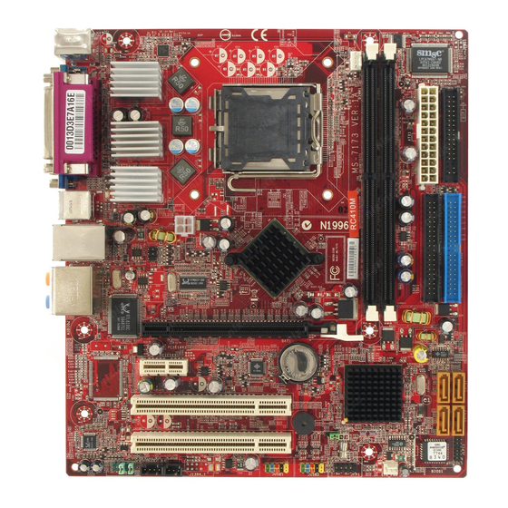
Page 15: Mainboard Layout
S-Out M: RS -Out Side Surround Line-In Line-Out PCIE16X1 PCIE 1X1 JPWD2 BATT VT6307 PCI1 ATI SB450 PCI 2 JCMOS1 ALC880 BIOS JAUD1 JCD1 CPU_FAN2 S PD O U T JUSB1 JUSB2 JFP1 J1394_1 RC410M Series (MS-7173 v1.X) M-ATX Mainboard... -
Page 16: Packing Checklist
MS-7173 M-ATX Mainboard Packing Checklist MSI Driver/Utility CD SATA Cable (Optional) MSI motherboard Standard Cable for Standard Cable for Power Cable Floppy Disk IDE Devices 1394 Bracket (Optional) USB Bracket (Optional) Back IO Shield * The pictures are for refer- enc e only. -
Page 17: Chapter 2. Hardware Setup
Hardware Setup Chapter 2. Hardware Setup Hardware Setup This chapter provides you with the information about hardware setup procedures. W hile doing the installation, be careful in holding the c omponents and follow the installation procedures . For s ome components, if you install in the wrong orientation, the components will not work properly. -
Page 18: Quick Components Guide
MS-7173 M-ATX Mainboard Quick Components Guide CPU_FAN1, p.2-12 JPW1, p.2-9 CPU, p.2-3 DDR DIMMs, p.2-7 JTV1, p.2-18 ATX1, p.2-9 Back Panel I/O, p.2-10 FDD1, p.2-12 IDE1/2, p.2-13 JPWD1,p.2-20 PCI Express Slots, p.2-21 SATA1~4, p.2-14 PCI Slots, p.2-21 JAUD1, p.2-15 CPU_FAN2, p.2-12... -
Page 19: Central Processing Unit: Cpu
W hen you are installing the CPU, make sure to install the cooler to prevent overheating. If you do not have the CPU cooler, contact your dealer to purchase and install them before turning on the computer. For the latest information about CPU, please visit http://www.msi.com.tw/program/ products/mainboard/mbd/pro_mbd_cpu_support.php. MSI Reminds You... -
Page 20: Cpu & Cooler Installation
MS-7173 M-ATX Mainboard CPU & Cooler Installation W hen you are installing the CPU, make sure the CPU has a cooler attached on the top to prevent overheating. If you do not have the cooler, contact your dealer to purchase and install them before turning on the computer. Meanwhile, do not forget to apply some silicon heat transfer compound on CPU before installing the heat sink/cooler fan for better heat dispersion. - Page 21 Hardware Setup 5. The CPU has a plastic cap on it to 6. Remove the cap from lever hinge side protect the contact from damage. (as the arrow shows). The pins of Before you have installed the CPU, socket reveal. always cover it to protect the socket pin.
- Page 22 MS-7173 M-ATX Mainboard 12. Press down the load lever lightly 11. Visually inspect if the CPU is seated onto the load plate, and then secure well into the socket, then remove the the lever with the hook under reten- CPU Clip with 2 fingers. Then cover tion tab.
-
Page 23: Memory
Hardware Setup Memory The mainboard provides two 240-pin non-ECC DDR II 667 DIMMs and supports up to 2GB system memory. For more information on compatible components, please visit http://www.msi.com.tw/ program/products/mainboard/mbd/pro_mbd_trp_list.php. DIM M1~DIMM2 (from left to right) Memory Population Rules This mainboard supports DDR II 667 memory interface. -
Page 24: Installing Ddr Ii Modules
MS-7173 M-ATX Mainboard Installing DDR II Modules 1. The DDR II DIMM has only one notch on the center of module. The module will only fit in the right orientation. 2. Insert the DIMM memory module vertically into the DIMM slot. Then push it in until the golden finger on the memory module is deeply inserted in the socket. -
Page 25: Power Supply
JPW1 Pin Definition JPW1 SIGNAL MSI Reminds You... 1. These two connectors connect to the ATX power supply and have to work together to ensure stable operation of the mainboard. 2. Power supply of 350 watts (and above) is highly recommended for system stability. -
Page 26: Back Panel
MS-7173 M-ATX Mainboard Back Panel CS-Out L-In Parallel 1394 Port M ou se (Optional) RS-Out L-Out Keyboard Serial Port VGA Port USB Ports Side Surround VGA Port M ouse/Keyboard Connector Pin5 Mouse/KBD Clock Pin6 NC Pin4 VCC Pin3 GND Pin1... -
Page 27: Hardware Setup
Hardware Setup 10/100 LAN Jack (Optional) IEEE 1394 Port (Optional) 10/100 LAN SIGNAL SIGNAL DESCRIPTION Transmit Differential Pair Transmit Differential Pair TPB- Receive Differential Pair TPB+ TPA- Not Used TPA+ Not Used Receive Differential Pair Not Used Not Used USB Ports Gigabit LAN Jack (Optional) SIGNAL DESCRIPTION... -
Page 28: Connectors
MS-7173 M-ATX Mainboard Connectors Floppy Disk Drive Connector: FDD1 The mainboard provides a standard floppy disk drive connector that supports 360K, 720K, 1.2M, 1.44M and 2.88M floppy disk types. FDD1 Fan Power Connectors: CPU_FAN1 / CPU_FAN2 The fan power connectors support system cooling fan with +12V. W hen connecting... -
Page 29: Ata133 Hard Disk Connectors: Ide1 & Ide2
IDE2 (Secondary IDE Connector) IDE2 can also connect a Master and a Slave drive. MSI Reminds You... If you install two hard disks on cable, you must configure the second drive to Slave mode by setting its jumper. Refer to the hard disk docu- mentation supplied by hard disk vendors for jumper setting instructions. -
Page 30: Serial Ata Connectors: Sata1~Sata4
MS-7173 M-ATX Mainboard Serial ATA Connectors: SATA1~SATA4 The ATI SB450 SouthBridge supports four serial ATA connectors SATA1~SATA4. SATA1~SATA4 are high-speed Serial ATA interface ports. Each supports 1 genera- tion serial ATA data rates of 150MB/s and is fully compliant with Serial ATA 1.0 specifications. -
Page 31: Cd-In Connector: Jcd1
Left channel audio signal to front panel AUD_RET_L Left channel audio signal return from front panel MSI Reminds You... If you don’t want to connect to the front audio header, pins 5 & 6, 9 & 10 have to be jumpered in order to have signal output directed to the rear audio ports. -
Page 32: Ieee 1394 Connectors: J1394_1 (Optional)
MS-7173 M-ATX Mainboard IEEE 1394 Connectors: J1394_1 (Optional) The mainboard provides one 1394 pin header that allows you to connect IEEE 1394 ports via an external IEEE1394 bracket (optional). J1394_1 Pin Definition SIGNAL SIGNAL TPA+ TPA- Ground Ground TPB+ TPB-... -
Page 33: Front Panel Connectors: Jfp1
USB1- USB0+ USB1+ JUSB1, JUSB2 (USB 2.0) Key (no pin) USBOC Connected to JUSB1 or JUSB2 USB 2.0 Bracket (Optional) MSI Reminds You... Note that the pins of VCC and GND must be connected correctly to avoid possible damage. 2-17... -
Page 34: Tv-Out Connector: Jtv1 (Optional)
MS-7173 M-ATX Mainboard TV-Out Connector: JTV1 (Optional) The mainboard optionally provides a TV-Out connector for you to attach a TV-Out bracket. The TV-Out bracket offers two types of TV-Out connectors: S-Video and RCA Composite connector. Select the appropriate one to connect to the television and the television will be able to display PC’s information. -
Page 35: Spdif-Out Connector: Spdout (Optional)
Hardware Setup SPDIF-Out Connector: SPDOUT (Optional) This connector is used to connect SPDIF (Sony & Philips Digital Interconnect Format) interface for digital audio transmission. SPDOUT SPDIF Connect to SPDOUT SPDIF Bracket (Optional) 2-19... -
Page 36: Clear Bios Password Jumper: Jpwd1
MS-7173 M-ATX Mainboard Jumpers The motherboard provides the following jumpers for you to set the computer’s function. This section will explain how to change your motherboard’s function through the use of jumpers. Clear BIOS Password Jumper: JPWD1 The jumper is used to clear the BIOS password. To clear the password, open the jumper and restart your computer. -
Page 37: Slots
Hardware Setup Slots The motherboard provides one PCI Express x1 slot, one PCI Express x16 slot, and two 32-bit/33MHz PCI slots. PCI (Peripheral Component Interconnect) Express Slots The PCI Express slots support high-bandwidth, low pin count, and serial interconnect technology. You can insert the expansion cards to meet your needs. W hen adding or removing expansion cards, make sure that you unplug the power supply first. -
Page 38: Chapter 3. Bios Setup
SETUP. ² You want to change the default settings for customized features. MSI Reminds You... 1. The items under each BIOS category described in this chapter are under continuous update for better system performance. -
Page 39: Entering Setup
MS-7173 M-ATX Mainboard Entering Setup Power on the computer and the system will start POST (Power On Self Test) process. W hen the message below appears on the screen, press <DEL> key to enter Setup. Press DEL to enter SET UP If the message disappears before you respond and you still wish to enter Setup, restart the system by turning it OFF and On or pressing the RESET button. -
Page 40: Getting Help
BIOS Setup Getting Help After entering the Setup menu, the first menu you will see is the Main Menu. M ain M enu The main menu lists the setup functions you can make changes to. You can use the control keys ( to select the item. -
Page 41: The Main Menu
MS-7173 M-ATX Mainboard The Main Menu Once you enter BIOS CMOS Setup Utility, the Main Menu (Figure 1) will appear on the screen. The Main Menu allows you to select from twelve setup functions and two exit choices. Use arrow keys to select among the items and press <Enter> to accept or enter the sub-menu. - Page 42 BIOS Setup H/W Monitor This entry shows your PC health status. Load Optimized Defaults Use this menu to load the default values set by the mainboard manufacturer specifi- cally for optimal performance of the mainboard. BIOS Setting Password Use this menu to set the password for BIOS. Save &...
-
Page 43: Standard Cmos Features
MS-7173 M-ATX Mainboard Standard CMOS Features The items in Standard CMOS Features Menu are divided into several categories. Each category includes no, one or more than one setup items. Use the arrow keys to highlight the item and then use the <PgUp> or <PgDn> keys to select the value you want in each item. - Page 44 BIOS Setup drive type is not matched or listed, you can use [Manual] to define your own drive type manually. If you select [Manual], related information is asked to be entered to the following items. Enter the information directly from the keyboard. This information should be provided in the documentation from your hard disk vendor or the system manufacturer.
-
Page 45: Advanced Bios Features
MS-7173 M-ATX Mainboard Advanced BIOS Features Quick Boot Setting the item to [Enabled] allows the system to boot within 5 seconds since it will skip some check items. Available options: [Enabled], [Disabled]. Boot Sector Protection This function protects the BIOS from accidental corruption by unauthorized users or computer viruses. - Page 46 HT F unction, or unreliability and instability may occur.Settings: [Enabled], [Disabled]. MSI Reminds You... Enabling the functionality of Hyper-Threading Technology for your computer system requires ALL of the following platform Components: ®...
- Page 47 MS-7173 M-ATX Mainboard 1st/2nd/3rd Boot Device The items allow you to set the sequence of boot devices where BIOS attempts to load the disk operating system. Boot From Other Device Setting the option to [Enabled] allows the system to try to boot from other device if the system fails to boot from the 1st/2nd/3rd boot device.
-
Page 48: Advanced Chipset Features
BIOS Setup Advanced Chipset Features MSI Reminds You... Change these settings only if you are familiar with the chipset. DRAM Timing This field has the capacity to automatically detect all of the DRAM timing. If you set this field to [Manual], the following fields will be selectable. The settings are: [Auto], [Manual]. -
Page 49: Integrated Peripherals
MS-7173 M-ATX Mainboard Integrated Peripherals USB Controller This setting disables/enables the onchip USB controller. Setting options: [Enabled], [Disabled]. USB Device Legacy Support Set to [Enabled] if your need to use any USB 1.1/2.0 device in the operating system that does not support or have any USB 1.1/2.0 driver installed, such as DOS and SCO Unix. - Page 50 BIOS Setup IDE Device Configuration Press <Enter> to enter the sub-menu and the following screen appears: On-Chip IDE Controller The integrated peripheral controller contains an IDE interface with support for two IDE channels. Select [Disabled] to disable the integrated IDE controller, [Primary] to enable only the primary IDE controller, [Secondary] to enable only the secondary IDE controller, or [Both] to enable both IDE controllers.
- Page 51 MS-7173 M-ATX Mainboard Parallel Port This specifies the I/O port address and IRQ of the onboard parallel port. Parallel Port M ode [SPP] : Standard Parallel Port [EPP] : Enhanced Parallel Port [ECP] : Extended Capability Port [ECP + EPP]: Extended Capability Port + Enhanced Parallel Port...
-
Page 52: Power Management Setup
BIOS Setup Power Management Setup MSI Reminds You... S3-related functions described in this section are available only when your BIOS supports S3 sleep mode. ACPI Function This item is to activate the ACPI (Advanced Configuration and Power Management Interface) Function. If your operating system is ACPI-aware, such as Windows 98SE/ 2000/ME, select [Enabled]. - Page 53 MS-7173 M-ATX Mainboard Re-Call VGA BIOS from S3 W hen ACPI Standby State is set to [S3/STR], users can select the options in this field. Selecting [Enable] allows BIOS to call VGABIOS to initialize the VGA card when system wakes up (resumes) from S3 sleep state. The system resume time is short- ened when you disable the function, but system will need an AGP driver to initialize the VGA card.
- Page 54 The field specifies the time for Resume By RTC Alarm. Format is <hour> <minute><second>. MSI Reminds You... If you have changed this setting, you must let the system boot up until it enters the operating system, before this function will work.
-
Page 55: Pnp/Pci Configurations
MS-7173 M-ATX Mainboard PNP/PCI Configurations This section describes configuring the PCI bus system and PnP (Plug & Play) feature. PCI, or Peripheral Component Interconnect, is a system which allows I/O devices to operate at speeds nearing the speed the CPU itself uses when communicating with its special components. -
Page 56: H/W Monitor
EMI generated by modulating the pulses so that the spikes of the pulses are reduced to flatter curves. MSI Reminds You... 1. If you do not have any EMI problem, leave the setting at [Disabled] for optimal system stability and performance. But if you are plagued by EMI, select the value of Spread Spectrum for EMI reduction. - Page 57 MS-7173 M-ATX Mainboard Auto Disable PCI Clock This item is used to auto detect the PCI slots. W hen set to [Enabled], the system will remove (turn off) clocks from empty PCI slots to minimize the electromagnetic inter- ference (EMI). Settings: [Enabled], [Disabled].
-
Page 58: Load Optimized Defaults
BIOS Setup Load Optimized Defaults The Optimized Defaults are the default values set by the mainboard manufacturer specifically for optimal performance of the mainboard. W hen you select Load Optimized Defaults, a message as below appears: Pressing Y loads the default factory settings for optimal system performance. BIOS Setting Password W hen you select this function, a message as below will appear on the screen: Type the password, up to 8 characters in length, and press <Enter>. -
Page 59: Appendix A: Realtek Alc880 8-Channel Audio Function
Realtek ALC880 8-Channel Audio Appendix A: Realtek ALC880 8-Chan- nel Audio Function The mainboard is equipped with Realtek ALC880 chip, which provides support for 8-channel audio output, including 2 Front, 2 Rear, 1 Center and 1 Subwoofer channel. ALC880 allows the board to attach 2, 4, 6 or 8 speakers for better surround sound effect. -
Page 60: Installing The Realtek Hd Audio Driver
MS-7173 M-ATX Mainboard Installing the Realtek HD Audio Driver You need to install the driver for Realtek ALC880 codec to function properly before you can get access to 2-, 4-, 6- or 8- channel audio operations. Follow the proce- dures described below to install the drivers for different operating systems. - Page 61 Realtek ALC880 8-Channel Audio 3. Click Next to install the Realtek High Definition Audio Driver. Click here 4. Click Finish to restart the system. Select this option Click here...
-
Page 62: Software Configuration
MS-7173 M-ATX Mainboard Software Configuration After installing the audio driver, you are able to use the 2-, 4-, 6- or 8- channel audio feature now. Click the audio icon from the system tray at the lower-right corner of the screen to activate the HD Audio Configuration. It is also available to enable the audio driver by clicking the Azalia HD Sound Effect M anager from the Control Panel. -
Page 63: Sound Effect
Realtek ALC880 8-Channel Audio Sound Effect Here you can select a sound effect you like from the Environment list. Load EQ Setting Reset EQ Setting EQ Setting On/Off Save Preset Delete EQ Setting You may choose the provided sound effects, and the equalizer will adjust automatically. If you like, you may also load an equalizer setting or make an new equalizer setting to save as an new one by using the “Load EQ Setting”... - Page 64 MS-7173 M-ATX Mainboard Equalizer Selection Equalizer frees users from default settings; users may create their own preferred settings by utilizing this tool. 10 bands of equalizer, ranging from 100Hz to 16KHz. Save Reset The settings are 10 bands of equalizer...
- Page 65 Realtek ALC880 8-Channel Audio Frequently Used Equalizer Setting Realtek HD Audio Sound Manager provides you certain optimized equalizer settings that are frequently used for your quick enjoyment. [How to Use It] Other than the buttons “Pop” “Live” “Club” & “Rock” shown on the page, to pull down the arrow in “Others”...
-
Page 66: Mixer
MS-7173 M-ATX Mainboard Mixer In the Mixer part, you may adjust the volumes of the rear and front panels individually. 1. Playback You can adjust the volume of the speakers that you pluged in front or rear panel by select the Realtek HD Audio rear output or Realtek HD Audio front output items. - Page 67 Realtek ALC880 8-Channel Audio W hen you are playing the first audio source (for example: use W indows Media Player to play DVD/VCD), the output will be played from the rear panel, which is the default setting. Then you must to select the Realtek HD Audio front output from the scroll list first, and use a different program to play the second audio source (for example: use W inamp to play MP3 files).
- Page 68 MS-7173 M-ATX Mainboard 3. Playback control Tool Mute Playback device This function is to let you freely decide which ports to output the sound. And this is essential when multi- streaming playback enabled. M u te You may choose to mute single or multiple volume controls or to completely mute sound output.
- Page 69 Realtek ALC880 8-Channel Audio 4. Recording control Recording device Tool Back Line In/Mic, Front Line In Realtek HD Audio Digital Input Tool Show the following volume controls This is to let you freely decide which volume control items to be displayed. Advanced controls.
- Page 70 MS-7173 M-ATX Mainboard 5. Recording If you want to use microphone to record, usually the microphone is connected to the MIC jack (the pink one) in the rear panel. You can start recording in this case. If you’d like to connect your microphone to the front audio panel.
-
Page 71: Audio I/O
Realtek ALC880 8-Channel Audio Audio I/O In this tab, you can easily configure your multi-channel audio function and speakers. You can choose a desired multi-channel operation here. a. Headphone for the common headphone b. 2CH Speaker for Stereo-Speaker Output c. 4CH Speaker for 4-Speaker Output d. - Page 72 MS-7173 M-ATX Mainboard Correct M essage Assume to plug a headphone in the Green jack at back panel. The icon beside green jack become visible and the dialogue “connected device” pops up. Check the headphone, then click OK. As soon as OK is clicked, the icon beside green jack becomes “headphone”...
- Page 73 Realtek ALC880 8-Channel Audio Global Connector Settings Click to access global connector settings. 1. M ute rear panel output when front headphone plugged in Once this item is checked, whenever front headphone is plugged, the music that is playing from the back panel, will be stopped. 2.
- Page 74 MS-7173 M-ATX Mainboard S/PDIF Short for Sony/Philips Digital Interface, a standard audio file transfer format. S/PDIF allows the transfer of digital audio signals from one device to another without having to be converted first to an analog format. Maintaining the viability of a digital signal pre- vents the quality of the signal from degrading when it is converted to analog.
- Page 75 Realtek ALC880 8-Channel Audio Test Speakers You can select the speaker by clicking it to test its functionality. The one you select will light up and make testing sound. If any speaker fails to make sound, then check whether the cable is inserted firmly to the connector or replace the bad speakers with good ones.
-
Page 76: Microphone
MS-7173 M-ATX Mainboard Microphone In this tab you may set the function of the microphone. Select the Noise Suppres- sion to remove the possible noise during recording, or select Acoustic Echo Cancelltion to cancel the acoustic echo druing recording. Also, please use the drop-down list to choose the recording source from Realtek HD Audio real input or Realtek HD Audio front input. -
Page 77: 3D Audio Demo
Realtek ALC880 8-Channel Audio 3D Audio Demo In this tab you may adjust your 3D positional audio before playing 3D audio applica- tions like gaming. You may also select different environment to choose the most suitable environment you like. A-19... -
Page 78: Information
MS-7173 M-ATX Mainboard Information In this tab it provides some information about this HD Audio Configuration utility, including Audio Driver Version, DirectX Version, Audio Controller & Audio Codec. You may also select the language of this utility by choosing from the Language list. - Page 79 Realtek ALC880 8-Channel Audio Before you begin using the front panel function, please complete the following steps: 1. Please install the pinheaders of the front panel according to Chapter 2. 2. Select AC97 or Azalia in the BIOS setting (Chapter 3). 3.
-
Page 80: Using 2-, 4-, 6- & 8- Channel Audio Function
MS-7173 M-ATX Mainboard Using 2-, 4-, 6- & 8- Channel Audio Function Connecting the Speakers W hen you have set the Multi-Channel Audio Function mode properly in the software utility, connect your speakers to the correct phone jacks in accordance with the setting in software utility. - Page 81 Realtek ALC880 8-Channel Audio n 4-Channel M ode for 4-Speaker Output Back Panel Description: Connect two speakers to back panel’s Line Out connector and two speakers to the real-chan- nel Line Out connector. 4-Channel Analog Audio Output Line In Line Out (Front channels) Line Out (Rear channels) Line Out (Center and Subwoofer channel, but no functioning in this mode) Side Surround (in 7.1CH / 5.1CH)
- Page 82 MS-7173 M-ATX Mainboard n 6-Channel M ode for 6-Speaker Output Back Panel Description: Connect two speakers to back 6-Channel Analog Audio Output panel’s Line Out connector, two speakers to the rear-channel and two speakers to the cen- Line In ter/subwoofer-channel Line Out Line Out (Front channels) connectors.
- Page 83 Realtek ALC880 8-Channel Audio n 8-Channel M ode for 8-Speaker Output Back Panel Description: Connect two speakers to back panel’s Line Out connector, two speakers to the rear-channel, two speakers to the c enter/ 8-Channel Analog Audio Output subwoofer-channel Line Out connectors, and two speakers to the side-channel Line Out Line Out (Side channels)
-
Page 84: Appendix B: Ati Sata Raid Setup Guide
ATI SATA RAID Setup Guide Appendix B: ATI SATA RAID Setup Guide Two major challenges facing the storage industry today are (1): keep pace with increasing performance demands of computer systems by improving disk I/O throughput, and (2): provide data accessibility in the event of hard disk failure. To meet these two challenges, ATI south bridge SB400 supports four SATA ports and incorporates Silicon Image’s SiI 3112 Serial ATA host controller, together with Silicon Image’s Serial ATA RAID Management Software (SATARaid™). -
Page 85: Sata Raid Features
MS-7173 M-ATX Mainboard SATA RAID Features u RAID 0 and RAID 1 u On-line Mirror Rebuilding u RAID GUI Monitoring Utility: - Displays/Logs/Alerts Users to Vital RAID Set Information - Manages RAID Set Functions (configures, rebuilds, etc.) u RAID Set accommodates multiple size HDDs... -
Page 86: Disk Mirroring (Raid 1
ATI SATA RAID Setup Guide Disk Mirroring (RAID 1) Disk mirroring creates an identical twin for a selected disk by having the data simul- taneously written to two disks. This redundancy provides protection from a single disk failure. If a read failure occurs on one drive, the system reads the data from the other drive. -
Page 87: Creating Raid Sets
MS-7173 M-ATX Mainboard Creating RAID Sets Creating and deleting RAID sets and performing other RAID setting up operations are done in the BIOS. During bootup, a screen similar to the one below will appear for about 5 seconds. Press CTRL+S or the F4 key to enter the BIOS RAID Utility. -
Page 88: Bios Raid Utility Screen Description
ATI SATA RAID Setup Guide BIOS RAID Utility Screen Description u M ain M enu The Main Menu in the upper left corner is used to choose the operation to be performed. The selections are: 1. Create RAID Set is used to create a new RAID Set (RAID 0 or RAID 1). 2. -
Page 89: Resolving Conflicts
MS-7173 M-ATX Mainboard strategy. RAID sets can be created either automatically, or to allow the greatest flexibility, manually. 1. Select “Create RAID Set.” 2. Choose a RAID 0 Striped, or a RAID 1 Mirrored set. 3. Select if you want the utility to Automatically Configure or if you want to manually configure the RAID Set. -
Page 90: Low Level Formatting
ATI SATA RAID Setup Guide 1. Select “Resolve Conflicts” 2. Select the “Invalid RAID drive” entry in the Logical Drive Status window and press Enter. 3. Follow the prompts to resolve the conflict. Note that some conflict resolutions may result in the drive letter assignment changing; for example the RAID set may have been drive D: but after the conflict resolution, it may become drive E:. -
Page 91: Installing Raid Drivers (For Windows 2000/Xp Only
MS-7173 M-ATX Mainboard Installing RAID Drivers (for Windows 2000/XP only) Installing RAID Drivers during OS Install Follow the instructions in this section if you are performing a new installation of the OS (W indows 2000/XP), and wish to boot from a RAID drive connected to the SATA controller. - Page 92 ATI SATA RAID Setup Guide T he following screen shots are taken from the AT I driv er installation wizard.
- Page 93 MS-7173 M-ATX Mainboard B-10...
-
Page 94: Installing Sataraid Utility
ATI SATA RAID Setup Guide Installing SATARaid Utility Insert your W indows 2000/XP ATI driver CD into the CD-ROM/DVD drive. Run the setup.exe program on the CD and follow the setup instructions to complete the installation. The following screen shots are taken from the installation of SATARaid. B-11... - Page 95 MS-7173 M-ATX Mainboard B-12...
-
Page 96: Sataraid Gui
ATI SATA RAID Setup Guide SATARaid GUI can be launched from the Task Bar SATARaid GUI The SATARaid GUI offers the user the ability to easily monitor the RAID Set. To launch the GUI, simply double-click on the icon located in the bottom right hand corner of the Desktop. - Page 97 MS-7173 M-ATX Mainboard A RAID 1 Set Monitoring Example B-14...
- Page 98 ATI SATA RAID Setup Guide B-15...
- Page 99 MS-7173 M-ATX Mainboard B-16...
- Page 100 ATI SATA RAID Setup Guide A RAID 0 Set Monitoring Example B-17...
- Page 101 MS-7173 M-ATX Mainboard B-18...
- Page 102 ATI SATA RAID Setup Guide B-19...
- Page 103 MS-7173 M-ATX Mainboard B-20...
- Page 104 ATI SATA RAID Setup Guide B-21...
- Page 105 MS-7173 M-ATX Mainboard B-22...
- Page 106 ATI SATA RAID Setup Guide B-23...
-
Page 107: Configuring Raid 0 Set(S) With Windows Disk Manager
MS-7173 M-ATX Mainboard Configuring RAID 0 Set(s) with Windows Disk Manager Note: This section is only applicable to non-initiated drives. It is not applicable if the drives have been set up as RAID 0 with the BIOS utility. The W indows XP built-in Disk Manager can be used to set up installed SATA drives in Disk Striping (RAID 0) configuration. - Page 108 ATI SATA RAID Setup Guide If SATA drives had not been initialized, initialize the disk as Dynamic. Right click on Disk 0 and select ‘New Volume’. At ‘New Volume W izard’ select Striped for type of volume. B-25...
- Page 109 MS-7173 M-ATX Mainboard Total size of disk set for striping is set next. B-26...
- Page 110 ATI SATA RAID Setup Guide B-27...
- Page 111 MS-7173 M-ATX Mainboard B-28...
-
Page 112: Appendix C: Ati Surroundviewtm
ATI SURROUNDVIEW Appendix C: ATI SURROUNDVIEW ATI SURROUNDVIEW ™ is an integrated feature supported by the onboard ATI northbridge chipset. It provides the power and convenience of multi-adapter, multi- ® monitor support for computers that use an AGP- or PCI Express -based graphics card in conjunction with specific ATI integrated graphics processors (IGPs). -
Page 113: Getting Started
MS-7173 M-ATX Mainboard Getting Started SURROUNDVIEW ™ provides the power and convenience of multi-adapter, multi- monitor support for computers that use an AGP- or PCI Express®-based graphics card in conjunction with the following ATI integrated graphics processors (IGPs): u RADEON ®... -
Page 114: System Requirements
ATI SURROUNDVIEW System Requirements Supported ATI Products Integrated graphics processors (enabled by system BIOS): ® • RADEON XPRESS 200 ® • RADEON 9100 Pro ® • RADEON 9100 IGP ® • RADEON 9000 IGP AGP/PCIe™ graphics cards: ® • RADEON X800 series ®... -
Page 115: Installing A Graphics Card
MS-7173 M-ATX Mainboard Installing a Graphics Card MSI Reminds You... This section provides generic installation instructions only. In most c a s es a g rap hic s c a rd will c o me with sp eci fic in s ta llation instructions, in which case users should consult their graphics card manual and follow the instructions therein. - Page 116 ATI SURROUNDVIEW 4. Unscrew or unfasten and remove any existing graphics card from your computer. 5. Locate the appropriate slot and, if necessary, remove the metal back-plate c over. 6. Align your graphics card with the slot and press it in firmly until the card is fully seated.
-
Page 117: Enabling Surroundviewtm
MS-7173 M-ATX Mainboard Enabling SURROUNDVIEW Enabling the Integrated Graphics Processor In order to use SURROUNDVIEW ™, the integrated graphics processor (IGP) on the motherboard must be enabled in addition to the graphics card in the PCIe™ slot. Make sure the IGP is enabled (using the BIOS setup utility) in addition to the graphics card before continuing. -
Page 118: Frequently Asked Questions
ATI SURROUNDVIEW 6. Use the arrow keys to navigate to Integrated Peripherals, and then press Enter. The Integrated Peripherals screen appears. 7. Use the arrow keys to navigate to Init Display First and set it to PCI-E. 8. Use the arrow keys to navigate to Surroundview and set it to Enabled. 9. -
Page 119: Using Multiple Displays
MS-7173 M-ATX Mainboard Using Multiple Displays Setting Up Multiple Displays To use SURROUNDVIEW ™, connect display devices to the output connections of both your integrated graphics processor (IGP) and your PCI Express® graphics card. There will normally be three connections: one from the IGP and two from the graphics card. - Page 120 ATI SURROUNDVIEW u To set up a multi-monitor display 1. Right-click on a clear area of your desktop and choose Properties. The Display Properties dialog opens. 2. Select the Settings tab. 3. Click the Identify button to display a large number on each monitor. 4.
-
Page 121: Using Surroundviewtm
MS-7173 M-ATX Mainboard Using SURROUNDVIEW Business Applications Using SURROUNDVIEW ™, you can run multiple applications simultaneously — for example, a spreadsheet, a W eb browser and a stock trader could be run and viewed on separate screens at the same time. - Page 122 ATI SURROUNDVIEW 3. Open your W eb browser, and then drag it to monitor 2. Web browser displayed on monitor 2 4. Launch another instance of your W eb browser, and then drag it to monitor 3. Another Web browser displayed on monitor 3 C-11...
-
Page 123: Games
MS-7173 M-ATX Mainboard Games The following section uses Microsoft® Flight Simulator as an example of using SURROUNDVIEW ™ for games. Using SURROUNDVIEW ™, you can display a different Flight Simulator view on each of your monitors. MSI Reminds You... For best results, in the Flight Simulator Settings Display dialog, set the full screen resolution for each video adapter to match the desktop resolution for the corresponding display. - Page 124 ® Microsoft Flight Simulator with both Primary and Monitor 2 running MSI Reminds You... 1. When moving a 3D window, you may see some hesitation when crossing the boundary to a secondary display. After you move the 3D window to the secondary display, that scene will be displayed in 3D.
- Page 125 MS-7173 M-ATX Mainboard 4. From the Views menu, create another new window, and then drag it to monitor 3. ® Microsoft Flight Simulator using all three monitors C-14...
Need help?
Do you have a question about the MS-7173 and is the answer not in the manual?
Questions and answers