
Related Manuals for Airwell CKD Series


Summary of Contents for Airwell CKD Series
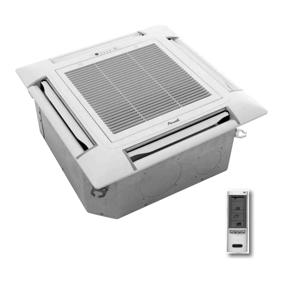
- Page 1 CKD DCI Series Indoor Units Outdoor Units CKD 025 DCI 72Z CKD 030 DCI 80Z REFRIGERANT R410A HEAT PUMP APRIL ─ 2010 www.airwell.com CONTENTS...
- Page 2 LIST OF EFFECTIVE PAGES LIST OF EFFECTIVE PAGES Note: Changes in the pages are indicated by a “Revision#” in the footer of each effected page (when none indicates no changes in the relevant page). All pages in the following list represent effected/ non effected pages divided by chapters.
- Page 3 TABLE OF CONTENTS Table of Contents INTRODUCTION ....................1-1 PRODUCT DATA SHEET ..................2-1 RATING CONDITIONS ..................3-1 OUTLINE DIMENSIONS ..................4-1 PERFORMANCE DATA & PRESSURE CURVES ..........5-1 SOUND LEVEL CHARACTERISTICS ..............6-1 ELECTRICAL DATA ....................7-1 WIRING DIAGRAMS .....................8-1 REFRIGERATION DIAGRAMS ................9-1 10. TUBING CONNECTIONS ..................10-1 11.
- Page 4 The new DCI 72Z, DCI 80Z split unit range comprises the following RC (heat pump) models: • CKD 025 • CKD 030 Main Features The DCI CKD series benefits from the most advanced technological innovations, namely: DC inverter technolegy R410a High COP ...
- Page 5 INTRODUCTION DCI 72Z DCI 80Z Outdoor Unit Feature Feature DCI 72, 80 Display LED’s 4 Outdoor Fan Variable speed DC Inverter M2L cable Port Tubing Connections Flare type interconnecting tubing to be produced on site. For further details please refer to the Operation/Installation Manual. Accessories RCW Wall Mounted Remote Control The RCW remote control is mounted on the wall, and controls the unit either as an infrared...
- Page 6 PRODUCT DATA SHEET PRODUCT DATA SHEET CKD 025 / DCI 72Z Model Indoor Unit CKD025 DCI Model Outdoor Unit DCI 72Z Installation Method of Pipe Flared Characteristics Units Cooling Heating Btu/hr 24570(5120-27300) 27300(5120-30030) Capacity 7.20(1.50-8.00) 8.00(1.50~8.80) 2.39(0.60-2.75) 2.21(0.50~2.50) Power input 3.01 3.61 EER (Cooling) or COP(Heating)
- Page 7 PRODUCT DATA SHEET CKD 030 / DCI 80Z Model Indoor Unit CKD030 DCI Model Outdoor Unit DCI 80 Z Installation Method of Pipe Flared Characteristics Units Cooling Heating Btu/hr 27280(6800~30000) 30690(5110~34100) Capacity 8.0(2.0-8.8) 9.0(1.5~10.0) 2.49(0.5-3.2) 2.49(0.5~3.1) Power input EER (Cooling) or COP(Heating) (4) 3.21 3.61 Energy efficiency class...
- Page 8 RATING CONDITIONS RATING CONDITIONS Standard conditions in accordance with ISO 5151 and ISO 13253 (for ducted units) and EN 14511. Cooling: Indoor: C DB 19 C WB Outdoor: 35 C DB Heating: Indoor: C DB Outdoor: 7 C DB 6 C WB Operating Limits Indoor...
- Page 9 OUTLINE DIMENSIONS OUTLINE DIMENSIONS Indoor Unit: CKD025 / CKD030 DCI Drain side Tubing side 780 (Hook-location) 840 (Body) 880 (Ceiling hole) 950 (Panel) Hook Body Ceiling Panel CKD025: B=240mm CKD030: B=310mm SM CKDDCI 1-A.1 GB CONTENTS...
- Page 10 OUTLINE DIMENSIONS Outdoor Unit: DCI 72Z, DCI 80Z SM CKDDCI 1-A.1 GB CONTENTS...
- Page 11 PERFORMANCE DATA & PRESSURE CURVES PERFORMANCE DATA & PRESSURE CURVES CKD025 / DCI 72Z 5.1.1 Cooling Capacity (kW) ID COIL ENTERING AIR DB/WB TEMPERATURE [ºC] OD COIL ENTERING AIR DATA 22/15 24/17 27/19 29/21 32/23 DB TEMPERATURE [ºC] 80 - 110 % of nominal -10 - 20 80 - 105 % of nominal (protection range)
- Page 12 PERFORMANCE DATA & PRESSURE CURVES 5.1.3 Heating Capacity ID COIL ENTERING AIR DB TEMPERATURE [°C] OD COIL ENTERING AIR DB/WB DATA TEMPERATURE [°C] 3.64 3.12 2.59 -15/-16 1.55 1.66 1.77 4.81 4.28 3.76 -10/-12 1.75 1.86 1.97 5.68 5.16 4.63 -7/-8 1.90 2.01...
- Page 13 PERFORMANCE DATA & PRESSURE CURVES 5.1.5 Pressure Curves Cooling – Technician Mode) 5.1.5.1 Cooling Suction Pressure VS.Outdoor Temp’ Indoor 1150 DB/WB 1050 22/15 24/17 27/19 29/21 32/23 Outdoor DB Temperature Dischange Pressure VS.Outdoor Temp’ 3650 Indoor 3400 DB/WB 3150 22/15 2900 24/17 2650...
- Page 14 PERFORMANCE DATA & PRESSURE CURVES 5.1.5.2 Heating Suction Pressure VS.Outdoor Temp’ 1100 1000 Outdoor WB Temperature Dischange Pressure VS.Outdoor Temp’ 3750 3500 Indoor DB 3250 3000 2750 2500 2250 2000 1750 1500 Outdoor WB Temperature SM CKDDCI 1-A.1 GB CONTENTS...
- Page 15 PERFORMANCE DATA & PRESSURE CURVES CKD030 / DCI 80Z 5.2.1 Cooling Capacity (kW) ID COIL ENTERING AIR DB/WB TEMPERATURE [C] OD COIL ENTERING AIR DB DATA 22/15 24/17 27/19 29/21 32/23 TEMPERATURE [C] 80 - 110 % of nominal -10 – 20 80 - 105 % of nominal (protection range) 25 - 50 % of nominal...
- Page 16 PERFORMANCE DATA & PRESSURE CURVES 5.2.3 Heating Capacity ID COIL ENTERING AIR DB TEMPERATURE [°C] OD COIL ENTERING AIR DB/WB DATA TEMPERATURE [°C] 4.10 3.51 2.92 -15/-16 1.74 1.87 1.99 5.41 4.82 4.23 -10/-12 1.97 2.09 2.22 6.39 5.80 5.21 -7/-8 2.14 2.26...
- Page 17 PERFORMANCE DATA & PRESSURE CURVES 5.2.5 Pressure Curves Cooling – Technician Mode) 5.2.5.1 Cooling Suction Pressure VS.Outdoor Temp’ 1200 Indoor DB/WB 1100 22/15 1000 24/17 27/19 29/21 32/23 Outdoor DB Temperature Dischange Pressure VS.Outdoor Temp’ 3900 Indoor 3650 DB/WB 3400 22/15 3150 24/17...
- Page 18 PERFORMANCE DATA & PRESSURE CURVES 5.2.5.2 Heating Suction Pressure VS.Outdoor Temp’ 1000 Outdoor WB Temperature Dischange Pressure VS.Outdoor Temp’ 3700 3450 Indoor DB 3200 2950 2700 2450 2200 1950 1700 1450 Outdoor WB Temperature SM CKDDCI 1-A.1 GB CONTENTS...
- Page 19 SOUND LEVEL CHARACTERISTICS SOUND LEVEL CHARACTERISTICS Indoor Units Test Scheme Figure 1 Sound Pressure Level Spectrum (Measured as Figure 1) CKD025 DCI CKD030 DCI FAN SPEED LINE SM CKDDCI 1-A.1 GB CONTENTS...
- Page 20 SOUND LEVEL CHARACTERISTICS Outdoor Units MODEL SPL dB(A) SPW dB(A) Indoor Outdoor Cooling/Heating Cooling/Heating CKD025 DCI DCI 72Z 52/55 62/63 CKD030 DCI DCI 80Z 58/58 69/69 1.0 m Center for Unit Figure 2 Sound Pressure Level Spectrum ( Measured as Figure 2) DCI 72Z Cooling DCI 72Z Heating SM CKDDCI 1-A.1 GB...
- Page 21 SOUND LEVEL CHARACTERISTICS DCI 80Z Cooling DCI 80Z Heating SM CKDDCI 1-A.1 GB CONTENTS...
- Page 22 ELECTRICAL DATA ELECTRICAL DATA Single Phase Units MODEL CKD025 DCI CKD030 DCI Power Supply 1PH, 220–230VAC, 50 Hz Connected to Outdoor Starting Current Circuit Breaker rating Power Supply Wiring 3 × 2.5 mm No. X Cross Section Interconnecting Cable 4 ×...
- Page 23 WIRING DIAGRAMS WIRING DIAGRAMS Indoor Unit: CKD025, CKD030 DCI SM CKDDCI 1-A.1 GB CONTENTS...
- Page 24 WIRING DIAGRAMS Outdoor Units: DCI 72Z SM CKDDCI 1-A.1 GB CONTENTS...
- Page 25 WIRING DIAGRAMS Outdoor Units: DCI 80Z OUTDOOR UNIT CIRCUIT DIAGRAM PWR-SHED FORCED ALARM STANDBY P403 P404 P405 P406 TO AC MAINS (FOR POWER SOURCE FROM ODU) P108 P107 WHITE TO IDU ODU MODEL SETTING ODU0 ODU1 ODU2 ODU3 ODU MODEL BLUE P106 P(DCI80)
- Page 26 REFRIGERATION DIAGRAMS REFRIGERATION DIAGRAMS Heat Pump Models 9.1.1 CKD025, CKD030 Cooling mode Heating mode SM CKDDCI 1-A.1 GB CONTENTS...
- Page 27 TUBING CONNECTIONS TUBING CONNECTIONS TUBE (Inch) ¼” ⅜” ½” ⅝” ¾” TORQUE (Nm) Flare Nuts 15-18 40-45 60-65 70-75 80-85 Valve Cap 13-20 13-20 18-25 18-25 40-50 Service Port Cap 11-13 11-13 11-13 11-13 11-13 Valve Protection Cap-end Refrigerant Valve Port (use Allen wrench to open/close) Valve Protection Cap Refrigerant Valve Service Port Cap...
- Page 28 CONTROL SYSTEM CONTROL SYSTEM General Functions and Operating RulesThe DCI software is fully parametric. All the model dependent parameters are shown in Blue color and with Italic style [parameter]. The parameters values are given in the last section of this control logic chapter of the service manual. 11.1 System Operation Concept The control function is divided between indoor and outdoor unit controllers.
- Page 29 CONTROL SYSTEM Target frequency limits as a function of outdoor air temperature (OAT): OAT Range Cooling Mode limits Heating Mode limits OAT < 6 No limit 6 ≤ OAT < 15 MaxFreqAsOAT1H MaxFreqAsOATC 15≤ OAT<28 MaxFreqAsOAT2H 28≤ OAT No limit 11.2.3 Frequency Changes Control When the unit is running normally , the compressor frequency change rate is 1 Hz/sec.
- Page 30 CONTROL SYSTEM 11.3 Outdoor Fan Control Outdoor Fan Control for DCI72/80 7 outdoor fan speeds are determined for each model. 3 speeds for cool and dry modes, and 3 speeds for heat mode, and a very low speed. Outdoor fan speed is a function of compressor frequency and outdoor air temperature (OAT). 4 routines for fan control are determined.
- Page 31 CONTROL SYSTEM 11.6 RV(Reversing Valve) Control Reversing valve is on in heat mode. Switching of RV state is done only after compressor is off for over 3 minutes. 11.7 Base Heater Control The base heater will be working only when RV is “ON” according to the following graph: Base Heater When OAT is faulty the base heater will be “ON”...
- Page 32 CONTROL SYSTEM 11.10.2 Indoor Fan Control in Heating Mode Indoor fan speed depends on the indoor coil temperature: 11.11 Auto Cool/Heat Mode When in auto cool heat mode unit will automatically select between cool and heat mode according to the difference between actual room temperature and user set point temperature (.T).
- Page 33 CONTROL SYSTEM 11.13.2 Indoor Coil Overheating Protection ICT Trend Fast Decreasing Decreasing No Change Increasing Fast Increasing >62 [60, 62) [55, 60) [52, 55) Norm Norm [48, 52) Norm Norm Norm [45, 48) Norm I<45 11.13.3 Compressor Overheating Protection Compressor Overheating Protection for DCI72/80 CTT Trend Fast Fast...
- Page 34 CONTROL SYSTEM 11.13.5 System Over Power Protection For DCI72/80 Delta PWR Power < -2000 [-2000,0) (0,2000] > 2000 PWR1 PWR2 PWR ≥ 3500 PWR ≥ 2900 3300≤PWR < 3500 2750≤PWR<2900 3100 ≤PWR <3300 2600≤PWR<2750 3000≤PWR < 3100 2450≤PWR<2600 2950 ≤PWR ≤3000 2300 ≤PWR≤2450 Norm Norm...
- Page 35 CONTROL SYSTEM 11.13.7 Water Level Protection Water Levels Desfinition: Level Connector Top View Level Don’t care Don’t care Normal Don’t care Don’t care Overflow (*) 1- Pin P1, P2, or P3 is connected to P4. 0- Pin P1, P2 or P3 is not connected to P4. The “overflow”...
- Page 36 CONTROL SYSTEM 11.14 Operating the Unit from Mode Button (On displayer) Forced operation allows to start, stop and operate in Cooling or Heating, in pre-set temperature according to the following table: Forced operation Mode Pre-set Temperature Cooling 20ºC Heating 28ºC 11.15 On Unit Controls and Indicators Indoor Unit controller Controls and Indicatiors for All Models Except for Floor/Ceiling...
- Page 37 CONTROL SYSTEM Self Test Jumper(J1) Jumper for production line check. DIP Switch Settings Compensation setting This setting activates the compensation to the return air temperature in heating mode. For indoor unit like cassette, the DIP switch J2 should be ON. Compensation Activated (factory setting) Deactivated...
- Page 38 CONTROL SYSTEM The indoor alarm outputs are defined according to the following table: Problem ICT is disconnected ICT is shorted RAT is disconnected RAT is shorted Reserved (for MSMP used as RGT fault) ICTE shorted/disconnected (when enabled) Undefined IDU family/model No Communication No Encoder Reserved...
- Page 39 CONTROL SYSTEM The outdoor alarm outputs are defined in the following way: Problem OCT is disconnected OCT is shorted CTT is disconnected CTT is shorted HST is disconnected (when enabled) HST is shorted (when enabled) OAT is disconnected (when enabled) OAT is shorted (when enabled) TSUC is disconnected (when enabled) TSUC is shorted (when enabled)
- Page 40 CONTROL SYSTEM 11.17 Test Mode 11.17.1 Entering Test Mode System can enter Test mode in two ways: Automatically when the following conditions exists for 30 minutes continuously: Mode = Cool, Set point = 16, Room temperature =)27(+2/-1) Outdoor temperature = 35(+2/-1) Mode = Heat, Set point = 30, Room temperature = 20±1, Outdoor temperature = 7±(+1/-2) Manually when entering diagnostics with the following settings: Mode = Cool, Set point = 16...
- Page 41 CONTROL SYSTEM 11.18.2 Outdoor Units SW Parameters Model dependent parameters for DCI72Z Compressor Parameters Value MinOFFTime MinOnTime MaxCTT1 MaxCTT2 MinSpeedAsCTT1 MinSpeedAsCTT2 MaxSpeedC MaxSpeedH Step1RPS Step2RPS Step3RPS NormAcc (sec/RPS) NormDec (sec/RPS) Down1(Sec/RPS) Down2 (Sec/RPS) DeiceAcc (Sec/RPS) DeiceDec (Sec/RPS) EEV Parameters Value NormEEVRate EEVCompOFFOpen EEVCompOFFTime...
- Page 42 CONTROL SYSTEM Model dependent parameters for DCI80Z № Name P (DCI80) MinFreqC MaxFreqC MinFreqH MaxFreqH In Text LoadDeadZone In Text ODUCodeC In Text ODUCodeH In Text EEVBase In Text EEVCpctyCrct Step1Freq Step2Freq Step3Freq OFMinRPM OFMaxRPM NightRPM OFNNoiseMaxRPM CTTOH1 CTTOH2 CTTOH3 CTTOH4 13.5 CCROC1...
- Page 43 TROUBLESHOOTING TROUBLESHOOTING WARNING!!! When Power Up – the whole outdoor unit controller, including the wiring, is under HIGH VOLTAGE!!! Never open the Outdoor unit before turning off the Power!!! When turned off, the system is still charged (400V)!!! It takes about 3 Min. to discharge the system. Touching the controller before discharging may cause an electrical shock!!! For safe handling of the controller please refer to section 12.6 below.
- Page 44 TROUBLESHOOTING SYMPTOM PROBABLE CAUSE CORRECTIVE ACTION Units goes into protections Control problem or Perform diagnostics (See 12.3 below), and and compressor is stopped refrigeration system follow the actions described. with no clear reason problem Compressor motor is Phase order to Check compressor phase order.
- Page 45 TROUBLESHOOTING 12.3.1 Indoor Unit Diagnostics Problem RT-1 is disconnected RT-1 is shorted RT-2 is disconnected RT-2 is shorted Reserved Communication mismatch No Communication No Encoder Reserved Outdoor Unit Fault … Reserved Defrost protection Deicing Protection Outdoor Unit Protection Indoor Coil HP Protection Overflow Protection Reserved EEPROM Not Updated...
- Page 46 TROUBLESHOOTING Fault Probable Cause Corrective Action The power supply indicator (red There is no correct voltage between -If the voltage is low repair power led) doesn’t light up. the line and neutral terminals on supply. main P.C.B. -If there is no voltage repair general wiring.
- Page 47 TROUBLESHOOTING Fault Probable Cause Corrective Action No air supply at indoor unit, -Indoor fan motor is blocked or - Check voltage,repair wiring if compressor operates. turns slowly. necessary. -indoor fan run capacitor faulty. - motor windings are shorted. -Check fan wheel if it is tight enough on motor shaft,tighten if necessary.
- Page 48 TROUBLESHOOTING 12.3.4 Outdoor Unit Diagnostics and Corrective Actions Fault Probable Cause Corrective Action Sensors failures of all types Check sensors connections or replace sensors. IPM Fault Electronics HW problem Check all wiring and jumper settings, if OK, replace electronics. Bad EEPROM No action, unless special parameters are required for unit operation.
- Page 49 TROUBLESHOOTING 12.5.3 Checking the Outdoor Fan Motor. Enter Test Mode (where the OFAN speed is high) Check the voltage between lead wires according to the normal value as following: Between red wire and black wire: 310VDC +/- 20V Between orange wire and black wire: 15VDC +/- 1V ...
- Page 50 EXPLODED VIEWS AND SPARE PARTS LISTS EXPLODED VIEWS AND SPARE PARTS LISTS 13.1 Indoor Unit: CKD 025, CKD 030 DCI - Exploded View SM CKDDCI 1-A.1 GB 13-1 CONTENTS...
- Page 51 EXPLODED VIEWS AND SPARE PARTS LISTS 13.2 Indoor Unit: CKD 025, CKD 030 DCI - Exploded View 13-2 SM CKDDCI 1-A.1 GB CONTENTS...
- Page 52 Indoor Unit: CKD 025 DCI - Spare Part List Item Description Quan. P0000371694 Grill/Airwell P0000371695 Filter 202301300044 Water-Level Switch Assy. 201109990016 Front Panel/Airwell 202401100017 Capacitor For Fan Motor 3.5uF 201552390004 Evaporator Assy. 202400610001 Pump 202742000006 Drain Pipe P0000146588 Flap 202242500075...
- Page 53 Indoor Unit: CKD 030 DCI - Spare Part Item Description Quan. P0000371694 Grill/Airwell P0000371695 Filter /NKN 202301300044 Water-Level Switch Assy. 201109990016 Front Panel/Airwell 202401100017 Capacitor For Fan Motor 3.5uF 201552390005 Evaporator Assy./NKN80 202400610001 Pump 202742000006 Drain Pipe P0000146588 Flap 202242800075...
- Page 54 EXPLODED VIEWS AND SPARE PARTS LISTS 13.5 Outdoor Units: DCI 72Z - Exploded View 13.5.1 Outdoor Unit General Assembly SM CKDDCI 1-A.1 GB 13-5 CONTENTS...
- Page 55 EXPLODED VIEWS AND SPARE PARTS LISTS 13.5.2 Outdoor Unit DCI 72Z Spare Part List Part No. Description 465100000 Outlet Grid 4523652 Painted Left Cabinet Assy. 4523758 Nut M8 left 452960400 Outdoor Fan 461600002 4-Way Valve Assy. 452956700 4-Way Valve Coil 4526522 4-Way Valve R410A 466130001...
- Page 56 EXPLODED VIEWS AND SPARE PARTS LISTS 13.6 Outdoor Units: DCI 80Z - Exploded View Assembly 13.6.1 Outdoor Units - General SM CKDDCI 1-A.1 GB 13-7 CONTENTS...
- Page 57 EXPLODED VIEWS AND SPARE PARTS LISTS 13.6.2 Outdoor Unit: DCI 80Z - Spare Part List Item Description Quan. 465100000 Grill/ DCI Trio 4523652 PAINTED LEFT CABINET ASSY 4523758 Nut M8 left 452960400 Outdoor Fan 461600023 4-Way Valve Assy. 461030003 4-way Valve Coil 4526522 4-WAY VALVE R410A 466110008R...
- Page 58 OPTIONAL ACCESSORIES OPTIONAL ACCESSORIES 14.1 RCW Wall Mounted Remote Control 14.1.1 The RCW wall mounted remote control can be fitted to a large range and models, It can be used as IR (wirless mode) or wired controler.the RCW can control up to15 indoor units using the same settings (on its wired aplication).
- Page 59 OPTIONAL ACCESSORIES 14.2 RCW2 Wall Mounted Remote Control 14.2.1 The RCW2 wall mounted remote controler is a wired controler that can provide affective controling management up to 15 different settings and temp’ zones. The RCW2 can be connected up to a max’ of 32 units,allowing a max wiring length of 1000m for application on WNG LED indoor units an additional interface PCB is needed.
- Page 60 OPTIONAL ACCESSORIES 14.3 RCW / RCW2 Wiring Connections as Shown on KIT SM CKDDCI 1-A.1 GB 14-3 CONTENTS...
- Page 61 APPENDIX A APPENDIX A INSTALLATION AND OPERATION MANUALS ► INSTALLATION INSTRUCTION CKD DCI ► INFRARED REMOTE CONTROL RECEIVER ► OPERATION MANUAL RC-3 ► OPERATION MANUAL RC-4 ► OPERATION MANUAL RC-7 17-1 SM CKDDCI 1-A.1 GB CONTENTS...
Need help?
Do you have a question about the CKD Series and is the answer not in the manual?
Questions and answers