Table of Contents
Advertisement
Installation and maintenance manual
Manuel d'installation et de maintenance
Installations- und Wartungshandbuch
Manuale di installazione e di manutenzione
Manual de instalación y de mantenimiento
HRW
07 ÷ 12
English
WATER SOURCE HEAT PUMP
1.9
Ü
POMPE A CHALEUR SUR BOUCLE D'EAU
3 kW
WÄRMEPUMPE AN WASSERSCHLEIFE
POMPA DI CALORE SU CIRCUITO DI ACQUA
2.6
Ü
BOMBA DE CALOR EN CIRCUITO DE AGUA
3.7 kW
IOM HRW 02-N-11
IOM HRW
Part number / Code / Teil Nummer / Codice / Código :
Part number / Code / Teil Nummer / Codice / Código : 3990404
Supersedes / Annule et remplace / Annulliert und ersetzt /
Supersedes / Annule et remplace / Annulliert und ersetzt /
Annulla e sostituisce / Anula y sustituye : IOM HRW
Annulla e sostituisce / Anula y sustituye : IOM HRW 02-N-10
Français
02-N-11GB
Deutsch
3990404GB
02-N-10GB
Italiano
Español
Advertisement
Table of Contents

Related Manuals for Airwell HRW Series


Summary of Contents for Airwell HRW Series
- Page 1 Installation and maintenance manual Manuel d’installation et de maintenance Installations- und Wartungshandbuch Manuale di installazione e di manutenzione Manual de instalación y de mantenimiento 07 ÷ 12 English Français Deutsch Italiano Español WATER SOURCE HEAT PUMP Ü POMPE A CHALEUR SUR BOUCLE D’EAU 3 kW WÄRMEPUMPE AN WASSERSCHLEIFE POMPA DI CALORE SU CIRCUITO DI ACQUA...
- Page 3 INSTALLATION INSTRUCTION NOTICE D’INSTALLATION INSTALLATIONSHANDBUCH ISTRUZIONI INSTALLAZIONE INSTRUCCIONES DE INSTALACIÓN...
-
Page 4: Table Of Contents
CONTENTS GENERAL RECOMMENDATIONS .......................3 SAFETY DIRECTIONS ................................3 WARNING ....................................3 INSPECTION AND STORAGE ........................4 GENERALITIES ............................4 CONTENTS OF PARCEL ..........................4 DIMENSIONS ............................5 HANDLING ...............................5 NET WEIGHT ................................... 5 TECHNICAL SPECIFICATIONS ........................6 OPERATING LIMITS .................................. 6 ENVIRONMENT ......................................6 TEMPERATURE LIMITS ....................................6 FLOW LIMITS ...................................... -
Page 5: General Recommendations
IT IS MANDATORY TO CUTOFF POWER SUPPLY BEFORE STARTING TO WORK IN THE ELECTRIC CASING BOXES GENERAL RECOMMENDATIONS Please read the following safety precautions very carefully before installing the unit. SAFETY DIRECTIONS Follow the safety rules in forces when you are working on your appliance. The installation, commissioning and maintenance of these units should be performed by qualified personnel having a good knowledge of standards and local regulations, as well as experience of this type of equipment. -
Page 6: Inspection And Storage
INSPECTION AND STORAGE At the time of receiving the equipment carefully cross check all the elements against the shipping documents in order to ensure that all the crates and boxes have been received. Inspect all the units for any visible or hidden damage. -
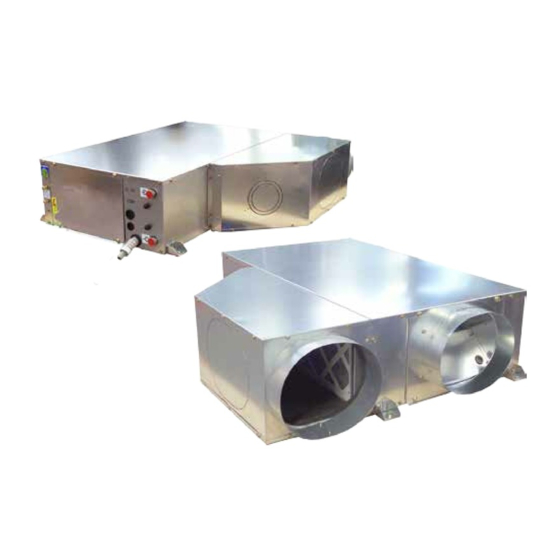
Page 7: Dimensions
DIMENSIONS AIR FILTER 600x200x25 Ø1/2" FEMALE GAS WATER OUTLET PRESSURE TAP PRESSURE TAP ELECTRICAL CONNECTIONS CONDENSATES OUTLET FLEXIBLE HOSE Ø16mm Ø1/2" FEMALE GAS WATER INLET HANDLING The appliance may be handled with a pallet truck or a forklift truck. NET WEIGHT MODELS WITH PLENUM WEIGTH... -
Page 8: Technical Specifications
TECHNICAL SPECIFICATIONS OPERATING LIMITS ENVIRONMENT This equipment is designed EXCLUSIVELY for INDOOR installation. In general, sheltered locations such as garages, roof space, etc, do not provide sufficient protection against extreme temperatures and/or humidity and may be harmful to the unit’s performance, reliability and service life. TEMPERATURE LIMITS Cooling Heating... -
Page 9: Électric Spécifications
ÉLECTRIC SPÉCIFICATIONS ELECTRICAL POWER SUPPLY A variance of ±10% is acceptable in relation to the operating voltage marked on the appliance’s Maker’s Plate. Operating voltages: ² 230V / 1 ph / 50 Hz (207 Volts minimum; 253 Volts maximum.) Comments: the stated voltages represent the accepted range. However, certain components may be subject to premature wear on appliances operating continuously, for extensive periods, on abnormally low or high voltages. -
Page 10: Ducting And Noise Level Reduction
DUCTING AND NOISE LEVEL REDUCTION Water circuit heat pumps are usually installed in conjunction with an air blowing duct. A return air duct may also be required. All ductwork shall be compliant with best air conditioning engineering practices. The air blowing duct system normally consists of a flexible connector mounted on the unit, a bridging section to link to the size of the main duct, a short section of straight duct, an elbow without a damper and a main duct with spurs equipped with distribution grilles as illustrated in the drawing below. -
Page 11: Connection Frame Dimensions
CONNECTION FRAME DIMENSIONS AIR BLOWING FRAME RETURN AIR INTAKE Ø250mm IN LINE BLOWING (STANDARD CONFIGURATION) REAR BLOWING RETURN AIR INTAKE FRAME WITHOUT PLENUM AIR FILTER 600x200x25 RETURN AIR INTAKE WITH PLENUM (OPTION) IN LINE BLOWING (STANDARD CONFIGURATION) FRESH AIR INTAKE Ø100 OR Ø125 REAR BLOWING (option) -
Page 12: Modifying The Air Blowing Direction
MODIFYING THE AIR BLOWING DIRECTION The unit sizes 07 to 12 can be supplied configured for either frontal air blowing, known as "IN LINE", or for side air blowing, known as "REAR". It is also possible to modify the air-blowing configuration on site. To achieve this: 1 - Remove the top panel 2 - Remove the fan motor access panel release a small length of motor cable. -
Page 13: Ventilation
VENTILATION An outdoor air intake (new air) may be required for ventilation. The blown air temperature must be controlled in order to avoid the temperature of the mixture of outdoor air and return air at the heat pump inlet exceeding the appliance’s operating limits. -
Page 14: Model 12
MODEL 12 System characteristics 320 340 360 380 420 440 480 500 540 560 580 600 640 660 680 700 720 740 Air flow (m UNCLAMPING THE COMPRESSOR The retention collar must be cut before starting the compressor for the first time; otherwise, it will vibrate, create considerable noise and result in refrigeration pipe breakages. -
Page 15: Hydraulic Connections
HYDRAULIC CONNECTIONS RECOMMENDATIONS FOR HYDRAULIC CONNECTIONS 1. It is recommended that all units are connected to a water supply and return pipe system of the Tickelman Loop type. The Tickelman Loop system is self-balancing and thus only requires manual balancing if a large number of units with different flow and pressure loss characteristics are connected to a single hydraulic loop. - Page 16 Never connect a unit to the water supply and return lines without completely cleaning and flushing out the hydraulic loop beforehand. After performing these operations, the units must be connected, with all valves completely open, ready for the system to be filled with water. COMMENT: In order to limit clogging the plate heat exchanger and to optimise unit operation, it is advisable to equip the system with a sieve filter (Ø...
-
Page 17: Recommendations For Cleaning And Flushing Out The System
RECOMMENDATIONS FOR CLEANING AND FLUSHING OUT THE SYSTEM 1. Before commissioning an appliance for the first time, the water loop must be cleaned and rinsed out to remove any dirt and manufacturing debris. If the appliances are equipped with isolation valves INTERCONNECTED (either electric or pressostatic), the water supply and CONVEYANCES... -
Page 18: Wiring Diagram And Legend
WIRING DIAGRAM AND LEGEND WIRING DIAGRAM SEE APPENDIX LEGEND N 752 SE 4248 models 07/09/012 cooling only or heatpump 230V +/-10% 50Hz POWER SUPPLY The power supply must be protected by an FFG mains circuit breaker. All the electrical installations and wiring associated with this equipment must comply with local installations regulations. -
Page 19: Pressostats Settings
CONTROL AND REGULATION : Local control module. : Anti-freezing protection sensors. : Intake air temperature sensor. : Outlet water temperature sensor. : Remote ON/OFF switch, 100 m maximum (Not supplied -Please consult us for longer distances). : CLOCK input remote ON/OFF : Flow switch relay REMOTE MANAGEMENT AND PROGRAMMING MODULE KIT (<100M) µBMS... -
Page 20: Rcl And Μbms Control Modules Wiring
RCL AND µBMS CONTROL MODULES WIRING Unscrew the lower screw on the RCL control. Separate the RCL control from its support bracket with the help of a flat bladed screwdriver Lower screw Checking the support bracket : Ensure that the wall surface is completely flat at the point where you wish to install the RCL control, as it is important that the support bracket is not twisted on installation, because any bending could lead to the control not clipping together properly and result in operating difficulties. - Page 21 Set the DIP switches marked J1 and J2 in accordance with your configuration nd the modes that are accessible. Dips switches J1 and J2 for parameterisation RCL control recommended Accessible modes PLUG setting Dip J1 Dip J2 Cool Heat Auto RC - RH - SH RC - RH - SH Clip the RCL control onto the support bracket.
-
Page 22: Μbms
µBMS The µBMS control module must be connected in accordance with the diagram below. Use screened twisted pair telephone wire with a section of between 0.12 and 0.5 mm²for wiring the control modules. Refer to the following chapter for detail of the appliances’ addressing. The use of the µBMS recall command is not compatible with the modbus communication. -
Page 23: Appliance Configuration
APPLIANCE CONFIGURATION FACTORY CONFIGURATION Type Description Cooling and thermodynamic Heating Thermodynamic Cooling + thermodynamic Heating or electric heating depending on appliance return water temperature Cooling only Cool + heat by electric heat Jumper Configuration Normal mode Forced mode dry contact (remote ON/OFF) CLIENT SETTINGS Jumper... -
Page 24: Return Air Temperature Measurement
RETURN AIR TEMPERATURE MEASUREMENT As the default factory setting, the jumpers are configured so that return air temperature measurement is performed via a sensor located on the RCL control module. If the RCL control module is not sited in the air-conditioned premises or is sited at a distance for various reasons, we recommend the use of the Return sensor (RT) located on the appliance itself. -
Page 25: Rcl Only
RCL ONLY 10 appliances can be connected to a single RCL remote control module. The maximum distance between the RCL and the first unit is 30 metres. The maximum distance between the RCL and the furthest unit is 100 metres. 100 m maximum between the 100m MAXI RCL and the last appliance. -
Page 26: Modbus
MODBUS The MODBUS supervision can be connected to a maximum of 123 appliances. ² The maximum distance between the RCL and the first unit is 30 metres. ² The maximum distance between the RCL and the furthest unit is 100 metres. The use of the µBMS recall command is not compatible with the modbus communication. -
Page 27: Addressing Procedure
ADDRESSING PROCEDURE BEFORE STARTING THE ADDRESSING PROCEDURE YOU MUST MAKE SURE THAT THE UNIT IS SWITCHED OFF AND THAT THERE IS NO POSSIBILITY OF IT STARTING UP UNEXPECTEDLY. Each machine connected to a µBMS central supervision unit or a MODBUS system must receive an address according to the procedure below. -
Page 28: Μbms Supervision Module
µBMS SUPERVISION MODULE The number of addresses is limited to 15 with a µBMS central supervision unit. The addressing will be performed using only DIP switches 1, 2, 3 and 4. The addressing carried out according to the table below means that all the units located in the same area will receive the same settings. -
Page 29: Motorised Water Valve
MOTORISED WATER VALVE The W/V output on the STORM 2 can be used for a 230 V connection to supply a motorised water valve (the valve motor capacity must not exceed 250 Watts). When this valve is installed on the system, it limits main circulation pump energy consumption as well as limiting the overall pressure losses in the hydraulic circuit. -
Page 30: Demand For Heating
Reminder: if one of these factors is situated at its minimum or maximum level, the other should be situated at a normal level in order to ensure the unit’s correct and normal operation. 2. Ensure that the thermostat is connected properly and set the set temperature below the ambient temperature of the zone to be cooled. -
Page 31: Maintenance And Servicing
MAINTENANCE AND SERVICING 1. Normal maintenance of the appliances is generally limited to replacing filters. 2. The filters must be changed at regular intervals. The frequency is dependent on the specific application conditions. Certain installations, for example in hotels where there large amounts of fluff due to the frequent bedding changes and the presence of fitted carpets, require more frequent filter changes. -
Page 32: Insufficient Cooling Or Heating Production
INSUFFICIENT COOLING OR HEATING PRODUCTION 1. Check that the thermostat is properly located in the zone to be heated or cooled and that it is not near to a source of cold or heat that may influence the reading. 2. Check the proper operation of the Return Air Temperature (RT) sensor, located on the fin exchanger. 3. -
Page 33: Alarm Codes
ALARM CODES GENERAL CODES LED ALARM ACTION FOR CANCELLING FAULT FAULT POSSIBLE CAUSE CORRECTIVE ACTION CODE CODE AFTER CORRECTION Three phase power supply phase reversal Reverse 2 phases Clogged filters. Clean the filters. Lack of airflow. Check the pressure losses on the air intake duct. The fault code is automatically cancelled Broken wire at the level of the STORM2 circuit Rewire correctly (c.f. -
Page 34: Heating Mode
HEATING MODE FAULT LED LARM POSSIBLE CAUSE CORRECTIVE ACTION ACTION FOR CANCELLING FAULT CODE CODE AFTER CORRECTION Insufficient airflow Check proper fan operation. Clogged filters. Clean or replace the filters. Too high aeraulic pressure loss due to an obstruc- Test the aeraulic network. tion in the intake duct. -
Page 35: In-Warranty Return Material Procedure
IN-WARRANTY RETURN MATERIAL PROCEDURE Material must not be returned without permission of our After Sales Department. To return the material, contact your nearest sales office and ask for a "return voucher". This return voucher shall be sent out with the returned material and shall contain all necessary information concerning the problem encountered. The return of the part does not constitute an order for replacement. - Page 37 APPENDIX / ANNEXE / ANLAGE / ALLEGATO / ANEXO APPENDIX ANNEXE ANLAGE ALLEGATO ANEXO...
- Page 38 APPENDIX / ANNEXE / ANLAGE / ALLEGATO / ANEXO...
- Page 39 APPENDIX / ANNEXE / ANLAGE / ALLEGATO / ANEXO WIRING DIAGRAM SCHEMAS ELECTRIQUES STROMLAUFPLANS SCHEMA ELETRICO ESQUEMA ELECTRICO TAKE CARE! These wiring diagrams are correct at the time of publication. Manufacturing changes can lead to modifications. Always refer to the diagram supplied with the product. ATTENTION Ces schémas sont corrects au moment de la publication.
- Page 40 APPENDIX / ANNEXE / ANLAGE / ALLEGATO / ANEXO WIRING DIAGRAM HRW 7-9-12 N752 3991281 SE 4248 µBMS > > > >...
- Page 41 APPENDIX / ANNEXE / ANLAGE / ALLEGATO / ANEXO START UP FORM / FICHE DE MISE EN SERVICE IDENTIFICATION CLIENT: N° affaire: ..............Nom de l'affaire: ............. Nom du client: ............Lieu de l'installation: ..........Nom du responsable local: ........: ...............
- Page 42 APPENDIX / ANNEXE / ANLAGE / ALLEGATO / ANEXO RELEVES SITE: Température ambiante: ..........Pression ambiante: ..........RELEVES ELECTRIQUES: Tension (L-N): ........... OUI NON Intensité (L): ............. Contact sec Marche /Arrêt à distance RELEVES DE FONCTIONNEMENT: MODE FROID MODE CHAUD Régime de la boucle d'eau °C °C...
- Page 43 The meaning of the above logo Le logo ci-dessus représentant Die Bedeutung des Logos mit der Il significato del logo qui sopra El significado de este logo que representing a crossed-out whee- une "poubelle barrée" signifie qu’il durchgestrichenen Mülltonne beste- rappresentato indica che il appa- representa un cubo de basura con led bin is that this unit must not be...
- Page 45 Y que se han aplicado los siguientes apartados de las normas armonizadas. EN 60 335-1 EN 60 335-2-40 EN 61 000-6-1 EN 61 000-6-3 EN 61 000-3-11 EN 61 000-3-12 EN 378 A Tillières sur Avre 27570 - FRANCE Le: 13/07/2010 Sébastien Blard Quality Manager AIRWELL Industrie France...
- Page 46 AIRWELL I ndustrIe rance Route de Verneuil 27570 Tillières-sur-Avre FRANCE : +33 (0)2 32 60 61 00 & : +33 (0)2 32 32 55 13 As part of our ongoing product improvement programme, our products are subject to change without prior notice. Non contractual photos.
Need help?
Do you have a question about the HRW Series and is the answer not in the manual?
Questions and answers