Sign In
Upload
Download
Table of Contents
Contents
Add to my manuals
Delete from my manuals
Share
URL of this page:
HTML Link:
Bookmark this page
Add
Manual will be automatically added to "My Manuals"
Print this page
×
Bookmark added
×
Added to my manuals
Manuals
Brands
Airwell Manuals
Heat Pump
PNX 30 DCI
Service manual
Airwell PNX 30 DCI Service Manual
Hide thumbs
1
2
3
4
5
6
7
8
9
10
11
12
13
14
15
16
17
18
19
20
21
22
23
24
25
26
27
28
29
30
31
32
33
34
35
36
37
38
39
40
41
42
43
44
45
46
47
48
49
50
51
52
53
54
55
56
57
58
59
60
61
62
63
64
65
66
67
68
69
70
71
72
73
74
75
76
77
78
79
80
81
82
83
84
85
86
87
88
89
90
91
page
of
91
Go
/
91
Contents
Table of Contents
Troubleshooting
Bookmarks
Table of Contents
Table of Contents
Main Features
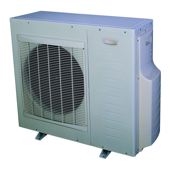
Outdoor Unit
Tubing Connections
Product Data Sheet
Rating Conditions
Operating Limits
Outline Dimensions
Indoor Unit: CKD
Performance Data & Pressure Curves
Rating Conditions
Sound Level Characteristics
Outdoor Units
Electrical Data
Wiring Diagrams
Refrigeration Diagrams
Tubing Connections
Control System
Compressor over Current no
Jumper Settings
Test Mode
Troubleshooting
No Problem
OCT Is Shorted/Disconnected
CTT Is Shorted/Disconnected
HST Is Shorted/Disconnected
OAT Is Shorted/Disconnected
OMT Is Shorted/Disconnected
RGT Is Shorted/Disconnected
RLT Is Shorted/Disconnected
Compressor IPM Fault / IPM Driver Pin / Compressor Current Sensor Fault
DC under Voltage
Troubleshooting no Problem Ao 5 4 3 2 1
PFC Current Sensor
Exploded Views and Spare Parts Lists
Appendix A
Advertisement
Quick Links
1
Main Features
2
Outdoor Unit
3
Product Data Sheet
4
Indoor Unit: Ckd
5
Control System
6
Troubleshooting
Download this manual
GCD 030 Series
Indoor Units
Outdoor Units
PNX 30 DCI
SX 30 DCI
GCD 030
CKD 30 DCI
DLS 30 DCI
REFRIGERANT
R410A
HEAT PUMP
JULY 2009
SM GCD030 1-A.0 GB
CONTENTS
Table of
Contents
Previous
Page
Next
Page
1
2
3
4
5
Advertisement
Chapters
Table of Contents
3
Troubleshooting No Problem Ao 5 4 3 2 1
72
Table of Contents
Need help?
Do you have a question about the PNX 30 DCI and is the answer not in the manual?
Ask a question
Questions and answers
Related Manuals for Airwell PNX 30 DCI
Inverter Airwell DLS 18 DCI Service Manual
Dls dc inverter series (183 pages)
Heat Pump Airwell SX 9 DCI Service Manual
Sx dci series (88 pages)
Heat Pump Airwell PAC HT Series Engineering Data Manual
High temperature air-to-water heat pumps (20 pages)
Heat Pump Airwell KXL DCI Series Service Manual
(55 pages)
Heat Pump Airwell FLO 9 DC INV Technical Manual
Multi split duo dci (62 pages)
Heat Pump Airwell HRW 019 Installation And Maintenance Manual
Heat pump on the water loop (35 pages)
Heat Pump Airwell Aqu@Scop HT SPLIT 12-6 Installation Instruction
Air-water heat pump (84 pages)
Heat Pump Airwell WELLEA WT RCW30 Technical Manual
(70 pages)
Heat Pump Airwell WELLEA HT Service Manual
(170 pages)
Heat Pump Airwell Monobloc R32 Operation Manual
(51 pages)
Heat Pump Airwell XLM9 Installation And Maintenance Manual
Multisplits trio high tech (30 pages)
Heat Pump Airwell ODMA-100T-09M22-19 Installation Manual
(42 pages)
Heat Pump Airwell AQL20-75 Installation And Maintenance Manual
Air cooled water chillers and heat pumps (76 pages)
Heat Pump Airwell AW-XDO009-H11 Installation Manual
Xdo series. direct expansion console water source dc inverter technology silent heat pump (24 pages)
Heat Pump Airwell HRW Series Installation And Maintenance Manual
Water source heat pump (46 pages)
Heat Pump Airwell AWAU-YBDE012-H11 Service Manual
Fwde series (32 pages)
This manual is also suitable for:
Gcd 030
Ckd 30 dci
Dls 30 dci
Sx 30 dci
Table of Contents
Print
Rename the bookmark
Delete bookmark?
Delete from my manuals?
Login
Sign In
OR
Sign in with Facebook
Sign in with Google
Upload manual
Upload from disk
Upload from URL


Need help?
Do you have a question about the PNX 30 DCI and is the answer not in the manual?
Questions and answers