Table of Contents
Advertisement
Installation and maintenance manual
Manuel d'installation et de maintenance
Installations- und Wartungshandbuch
Manuale di installazione e di manutenzione
Manual de instalación y de mantenimiento
AQL/AQH 20-75
AQC 40-75
English
20
Air Cooled Water Chillers and Heat Pumps
Refroidisseurs de liquide à condensation par air et pompes à chaleur air-eau
77 kW
Luftgekühlte Flüssigkeitskühler und Wärmepumpen
Refrigeratori d'Acqua e Pompe di Calore Raffreddati ad Aria
20
Enfriadores de Agua y Bomba de Calor Condensadas con Aire
86 kW
IOM AQ410-N.3GB
Part number / Code / Code / Codice / Código :
Supersedes / Annule et remplace / Annulliert und ersetzt / Annulla e sostituisce /
Anula y sustituye :
Notified Body / Organisme Notifié / Benannte Zertifizierungsstelle / Organismo
Notificato / Organismo Notificado N°. 1115
Français
035B09040-000D
035B09040-000C
Deutsch
Italiano
ISO 9001 certified management system
Español
Advertisement
Table of Contents

Related Manuals for Airwell AQL20-75


Summary of Contents for Airwell AQL20-75
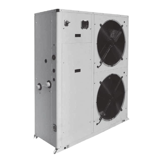
- Page 1 Installation and maintenance manual Manuel d'installation et de maintenance Installations- und Wartungshandbuch Manuale di installazione e di manutenzione Manual de instalación y de mantenimiento AQL/AQH 20-75 AQC 40-75 English Français Deutsch Italiano Español Air Cooled Water Chillers and Heat Pumps ...
-
Page 3: Table Of Contents
Table of Contents 1 - FOREWORD 7 - AQC CONTROL 1.1 Introduction ................2 7.1 Control of AQC with 2 compressors The "CHILLER CONTROL" system ........30 1.2 Warranty ................2 7.2 Display ................31 1.3 Emergency stop / Normal stop ..........2 7.3 Keyboard ................31 1.4 An introduction to this manual ..........2 7.4 Alarms ................32 2 - SAFETY... -
Page 4: Foreword
1 - Foreword 1.1 Introduction 1.3 Emergency stop / Normal stop Units, manufactured to state-of-the-art design and implementation The emergency stop of the unit can be enabled using the master standards, ensure top performance, reliability and fitness to any type switch on the control panel (move down the lever). -
Page 5: Safety
2 - Safety 2.1 Foreword The guards of the fans (only for units provided These units must be installed in conformity with the with air heat exchangers) must be always provisions of Machinery Directive 2006/42/EC, Low Voltage mounted and must never be removed before Directive 2006/95/EC, Pressure Vessels Directive 97/23/ de-energising the appliance. -
Page 6: Definitions
2 - Safety disassemble connections, filters, joints or other line items 2.2 Definitions do not use your hands to check for any pressure drops OWNER : means the legal representative of the company, body or individual who owns the plant where unit has been installed; he/she use tools in a good state of repair;... -
Page 7: Precautions During Maintenance Operations
2 - Safety periodically check the board’s internal wiring place a warning sign “do not turn on - maintenance in progress” on the external disconnecting switch do not use cables having an inadequate section or flying connections, even for limited periods of time or in an emergency make sure that on-off remote controls are inhibited wear suitable personal protective equipment (helmet, safety Prevention of other residual risks... -
Page 8: Safety Labels
2 - Safety 2.7 Safety labels Identification of the refrigerant - External door Use of filter and flow switch - Adjacent to fittings USARE SOLO E’OBBLIGATORIO L’USO DI FILTRO E FLUSSOSTATO ACQUA THE USE OF FILTER AND FLOW SWITCH IS MANDATORY EL USO DEL FILTRO Y DEL INTERRUPTOR DE FLUJO ES OBLIGATORIO R 410A L’UTILISATION DU FILTRE ET DU FLUXOSTAT EST OBLIGATOIRE... - Page 9 2 - Safety Electrical warning Grounding connection on the Read the instruction on the electrical board, Adjacent to the master switch electrical board adjacent to the connection ATTENZIONE ! ATTENTION ! Prima di Enlever aprire togliere l’alimentation tensione electrique avant d’ouvrir ACHTUNG ! CAUTION ! ATENCION !
- Page 10 2 - Safety 2.8 Safety regulations REFRIGERANT DATA SAFETY DATA : R410A Toxicity Low. If sprayed, the refrigerant is likely to cause frost burns. If absorbed by the skin, the danger is very limited; it may cause a slight irritation, and the liquid is degreasing. Unfreeze the affected skin with water. Contact with skin Remove the contaminated clothes with great care - in the presence of frost burns, the clothes may stick to the skin.
- Page 11 2 - Safety 2.8 Safety regulations (continued) REFRIGERANT DATA SAFETY DATA : R410A Do not inhale concentrated vapours. Their concentration in the atmosphere should not exceed the minimum preset values and should be maintained below the professional threshold. Being more weighty General precautions than the air, the vapour concentrates on the bottom, in narrow areas.
-
Page 12: Safety Regulations
2 - Safety 2.8 Safety regulations (continued) LUBRICANT OIL DATA SAFETY DATA : POLYESTER OIL (POE) Classification Not harmful. May cause slight irritation. Does not require first aid measures. It is recommended to follow usual personal hygiene measures, including washing the exposed skin with soap and water several times a day. Contact with skin It is also recommended to wash your overalls at least once a week. -
Page 13: Transport, Handling And Storage
3 - Transport, Handling and Storage AQL/AQH units are supplied fully assembled and tested (except for Space requirements request to handling accessories supplied loose in the units – absorbers, filter, etc.). They are ready to be installed and started on the field. R410A units are only charged with liquid refrigerant and with oil in the quantity required for operation. -
Page 14: Anchoring
3 - Transport, Handling and Storage Never store the units in a room where temperature is above Until the unit is ready for operation, do not 50 °C (R410A units) or where the units are directly exposed to remove the plastic envelope and the coil the sunlight. -
Page 15: Installation
4 - Installation 4.1 Installation Site 4.2 External Water Circuit The external water circuit shall guarantee a Before installing the unit, make sure that constant water flow rate through the circulating the building structure and/or the supporting refrigerant/water heat exchanger (evaporator) surface can withstand the weight of the under steady operating conditions and in case device. - Page 16 4 - Installation External water circuit AQL/AQH 20 to 35 - R410A HYDROKIT INLET OUTLET components 1 Plate heat exchanger safety/control devices 2 Pump Inlet water temperature sensor 3 Draining valve Outlet water temperature sensor 4 Water buffer tank Water differential pressure switch (105 mbar) 5 Water filter Vent valve 6 Automatic water charging valve...
- Page 17 4 - Installation External water circuit AQL/AQH 40 to 75 - R410A - 1 Pump INLET OUTLET components safety/control devices 1 Plate heat exchanger Inlet water temperature sensor 2 Pump Outlet water temperature sensor 5 Water filter Vent valve (105 mbar) 7 Pressure expansion tank Water safety valve (3 bar) 8 Pressure point/drain valve...
-
Page 18: External Water Circuit
4 - Installation External water circuit AQL/AQH 40 to 75 - R410A - 1 Pump + tank INLET OUTLET components safety/control devices 1 Plate heat exchanger Inlet water temperature sensor 2 Pump Outlet water temperature sensor 3 Draining valve Vent valve (105 mbar) 4 Water buffer tank Water safety valve (3 bar) 5 Water filter... -
Page 19: Water Connections
4 - Installation 4.5 Water buffer tank Before filling the installation, remove any The accumulation tank which has been designed to be mounted impurity, such as sand, crushed stones and on AQL/AQH units is complete with all the hydraulic and electrical welding scales, coating drops and any other components required for the correct operation of the system. -
Page 20: Power Supply
4 - Installation CAUTIONS 4.6 Power supply The unit + tank system shall be equipped with a filter. Use the filter + union as it is shown by Figure 1. Before carrying out any operations on the electrical system, make sure that the unit is Figure 1 deenergized. - Page 21 4 - Installation Antifreeze Resistance Wiring Storage Kit (112 l) for AQL/AQH 20-35 - Dimensional Data Front view Side view Top view 4 holes Ø9 62.5 62.5 1352 1477 Water inlet on the plant side Ø1 ½" gas male Water outlet on the chiller side Ø1 ½" gas male Water filling Ø1/2"...
- Page 22 4 - Installation Electrical connections For 3-phase systems, check also that the unbalance between the phases does not exceed 2%. To perform this check, measure the differences between the voltage of each phase couple and their mean The unit must be installed on site according to the usual value during operation.
- Page 23 4 - Installation AQL/AQH Version - Electrical Connections TERMINAL BOARD ON THE MACHINE USER CONNECTIONS MAIN SWITCH POWER LINE 400/3+N/50+PE EXTERNAL WATER FLOW SAFETY SWITCH EXTERNAL INTERLOCK ALARMED UNIT MAX 0,5A @ 250Vac ON/OFF ON/OFF REMOTE SWITCH COMMON HEATING/COOLING SELECTION HOT/COLD NIGHT OR DOUBLE SET POINT MODE SELECTION...
-
Page 24: Electrical Connections
4 - Installation AQC Version - Electrical Connections... -
Page 25: Start-Up
5 - Start-up Check the operation of all the external equipment, and make sure The unit must be started for the first time by that the control devices of the plant are properly calibrated. personnel suitably trained by one of Authorised Start the pump and check that the water flow is correct. -
Page 26: Aql/Aqh Control
6 - AQL/AQH Control 6.1 Electronic Card Control Keyboard SM1 Switch SM1 switch : Test switch (internal) Starts an automatic testing procedure for all the main functions of – Position : machine OFF. The electrical heaters and pump may the unit. be enabled. -
Page 27: Dip Switches
6 - AQL/AQH Control 6.2 Dip Switches The control is provided with 2 DIP switch blocks: DSW1 (12 dips) and DSW2 (8 dips). Function of DSW1 DIPS (user setting) STANDARD Pump ON only if the unit is ON Pump always ON Step ventilation Continuous ventilation Pump Off in antifreeze protection... - Page 28 6 - AQL/AQH Control UnIt 2E or 2D PArA (Parameters) CSPT Select to show present value HSPT EPIC Select to show present value SEnS (Sensor) (if connected) CPS – saturated temperature EPS – saturated temperature OAT – OC1T – OC2T ALAr (Existing Faults) See alarm list below Scrolls through all active faults (if any)
- Page 29 6 - AQL/AQH Control MOdE Off, Cool OF2 - Outdoor fan 2 OFF or HI or LO Stat - status OF1 - Outdoor fan 1 OFF or HI or LO ON or OFF PUMP tH - Electrical heater ON or OFF ON or OFF C2 - compressor C1 - compressor...
-
Page 30: Alar And Log Menu
6 - AQL/AQH Control 6.3 ALAr and LOg Menus The last 10 recorded alarms are displayed in the LOg menu. The fol- The activated alarms of the unit are displayed in the ALAr menu. More alarms lowing table shows the alarm codes and description: can be activated at the same time. -
Page 31: Sens Menu - Sensor Reading
6 - AQL/AQH Control 6.4 SEnS Menu – Sensors reading Displayed Code Meaning entering water temp leaving water temp discharge pressure intake pressure sat. temperature (discharge) sat. temperature (intake) compressor’s discharge temp room air temp OCT 1 probe temperature in coil 1 OCT 2 probe temperature in coil 2 6.5 SIF version configuration... -
Page 32: Aqc Control
7 - AQC Control 7.1 Control of AQC with 2 compressors - The Introduction “CHILLER CONTROL” system This document contains the information and the operating instructions for AQC 2 compressors & electronic control. AQC units are provided with a microprocessor card which is fully programmed by default for the control of a condensing unit. -
Page 33: Display
7 - AQC Control 7.2 Display Access to the "display mask" of the machine status. User Manufactured Maintenance In/Out Setpoint Release On/Off Daily time zone The display is an LCD 4 lines x 20 columns. The quantities and the information about the operation of the unit are alternated in the form of subsequent screens, named. -
Page 34: Alarms
7 - AQC Control 7.4 Alarms Compressor Pump Aut/Man Code Alarm unit description Delay Notes Status Status Status Reset AL02 Flow meter/Interbloc alarm Parameters AL03 High pressure “manual reset” AL05 Failure of transducer B6-SP Auto 10 sec TXV only AL07 Failure of transducer B7-DP Auto 10 sec... -
Page 35: Product Description
8 - Product Description 8.1 General Information Evaporators Evaporators are made of stainless steel plates. They are thermally AQL/AQH units are one-block type with one refrigerant circuit. They insulated by means of a thick flexible insulating mattress with closed are intended to cool down the water required for any air-conditioning cells. -
Page 36: Accessories Aql/Aqh 20-35
8 - Product Description 8.2 Accessories AQL/AQH 20-35 Corrosion proofing protection for condensing Two-level optional coil finishing : Water Filter 1) Fin guard Silver. 1-1/2” filter is included in the supplied equipment. 2) Blue fins. It is supplied loose and has to be mounted by the customer. Intrusion proofing protection for condensing A galvanised and painted steel wire net protection is assembled outside the unit. - Page 37 8 - Product Description Airway Packaging Fan speed control -10 °C Fan speed control is available as accessory to allow the chiller to Complete wooden package for units without refrigerant and with operate down to external air temperature. nitrogen precharge. No refrigerant charge is shipped loose with the unit.
- Page 38 8 - Product Description In/out valve kit In/Out valve kit is available as accessory. Parameters setting when install fan speed control Add in the Control Board when install the Fan Speed Control...
-
Page 39: Accessories Aql/Aqh 40-75
8 - Product Description 8.3 Accessories AQL/AQH 40 to 75 - with 1 pump that guarantee 150 kPa of available static pressure; - with 2 pumps that guarantee 150 kPa of available static pressure Water Filter Water buffer tank It is assembled on the unit as a standard. The hydro module is available for the units with a pump;... - Page 40 8 - Product Description Gauges kit Gauges kit is available as accessory. It is shipped loose and it’s not possible to have it factory mounted. Fan speed control Fan speed control is available as accessory to allow the chiller to operate down to external air temperature.
- Page 41 8 - Product Description 8.4 Refrigerant flow diagram - AQL 20 to 35 - R410A OIL EQUAL. 1 HYDROKIT components 1 Compressor tandem scroll type 2 Air cooled condenser 3 Filter drier 4 Sight glass 5 Thermostatic expansion valve 6 Plate heat exchanger 7 Pump 8 Drain valve 9 Water buffer tank...
- Page 42 8 - Product Description Refrigerant flow diagram - AQH 20 to 35 - R410A EQUAL. 1 HYDROKIT components 1 Compressor tandem scroll type 2 4-way valve 3 Air cooled condenser 4 Biflow filter drier 5 Sight glass 6 Biflow thermostatic expansion valve 7 Liquid receiver 8 Plate heat exchanger 9 Pump...
- Page 43 8 - Product Description Refrigerant flow diagram - AQL 40 to 75 - R410A OIL EQUAL. INLET OUTLET AQL R410A (Fluid group 2) : components vessel cateGory (≥2)/evaluation module 1 Compressor tandem scroll type 2 / mod. D1 2 Air cooled condenser 3 Filter drier 4 Sight glass 5 Thermostatic expansion valve...
- Page 44 8 - Product Description Refrigerant flow diagram - AQH 40 to 75 - R410A OIL EQUAL. INLET OUTLET AQH R410A (Fluid group 2) : components vessel cateGory (≥2)/evaluation module 1 Compressor tandem scroll type 2 / mod. D1 2 4-way valve 3 Air cooled condenser 4 Biflow filter drier 5 Sight glass...
-
Page 45: Refrigeration Circuits
8 - Product Description Refrigerant flow diagram - AQC 40 to 75 - R410A INLET OIL EQUAL. OUTLET AQC R410A (Fluid group 2) : components vessel cateGory (≥2)/evaluation module 1 Compressor tandem scroll type 2 / mod. D1 2 Air cooled condenser safety / control devices Hazard cateGory / evaluation module High pressure switch (40.5 bar) -
Page 46: Technical Data
9 - Technical Data Hydraulic Features Units AQL/AQH 20-35 30-35 20-25 20-25 30-35 1700 2200 2700 3200 3700 4200 4700 5200 5700 6200 Water flow (l/h) unit external static pressure curves. plate heat exchanger water pressure drop curves. 30-35 20-25 1700 2200 2700... - Page 47 9 - Technical Data Evaporator water pressure drop - AQL/AQH 40 to 75 - R410A AQL/AQH 40-45 AQL/AQH 50 AQL/AQH 60-75 3000 4000 5000 6000 7000 8000 9000 10000 11000 12000 13000 14000 15000 16000 17000 18000 Water flow (l/h) Desuperheater water pressure drop - AQL/AQH 40 to 75 - R410A AQL/AQH 40-45 AQL/AQH 50-60...
- Page 48 9 - Technical Data Optional pump available static pressure - AQL/AQH 40 to 75 - R410A AQL/H 60-75 AQL/H 40-45 AQL/H 50 5500 6000 6500 7000 7500 8000 8500 9000 9500 1000 10500 11000 11500 12000 12500 13000 13500 14000 14500 15000 15500 16000 16500 17000 17500 Water flow (l/h) Note : The curves are referred to 2P+T unit.
- Page 49 9 - Technical Data 9.2 Physical data AQL 20 to 35 Power supply V/ph/Hz 400 ±( 10%)/3+N/50 Number of refrigerant circuits Total capacity steps 0-50-100 0-50-100 0-50-100 0-50-100 REFRIGERANT Type R410A Charge (1) COMPRESSOR Type Scroll Number Start-up type Direct Oil type N°of loading stages 0/100...
- Page 50 9 - Technical Data AQL 40 to 75 - BLN Version AQL BLN Power supply V/ph/Hz 400V/3/50Hz Number of refrigerant circuits Total capacity steps 0-50-100 0-50-100 0-50-100 0-44-56-100 0-50-100 0-50-100 REFRIGERANT Type R410A Charge (1) 10.7 11.9 14.3 15.5 17.9 COMPRESSOR Type Scroll...
- Page 51 9 - Technical Data AQL 40 to 75 - ELN Version AQL ELN Power supply V/ph/Hz 400V/3/50Hz Number of refrigerant circuits Total capacity steps % 0-50-100 0-50-100 0-50-100 0-44-56-100 0-50-100 0-50-100 REFRIGERANT Type R410A Charge (1) 10.7 11.9 14.3 15.5 17.9 COMPRESSOR Type...
- Page 52 9 - Technical Data AQL 40 to 75 - SIF Version AQL SIF Power supply V/ph/Hz 400V/3/50Hz Number of refrigerant circuits Total capacity steps % 0-50-100 0-50-100 0-50-100 0-44-56-100 0-50-100 0-50-100 REFRIGERANT Type R410A Charge (1) 10.7 11.9 14.3 15.5 17.9 COMPRESSOR Type...
- Page 53 9 - Technical Data AQH 20 to 35 Power supply V/ph/Hz 400 ±( 10%)/3+N/50 Number of refrigerant circuits Total capacity steps 0-50-100 0-50-100 0-50-100 0-50-100 REFRIGERANT Type R410A Charge (1) COMPRESSOR Type Scroll Number Start-up type Direct Oil type N°of loading stages 0/100 0/100 0/100...
- Page 54 9 - Technical Data AQH 40 to 75 - BLN Version AQH BLN Power supply V/ph/Hz 400V/3/50Hz Number of refrigerant circuits Total capacity steps % 0-50-100 0-50-100 0-50-100 0-44-56-100 0-50-100 0-50-100 REFRIGERANT Type R410A Charge (1) 10.7 11.9 14.3 15.5 17.9 COMPRESSOR Type...
- Page 55 9 - Technical Data AQH 40 to 75 - ELN Version AQH ELN Power supply V/ph/Hz 400V/3/50Hz Number of refrigerant circuits Total capacity steps % 0-50-100 0-50-100 0-50-100 0-44-56-100 0-50-100 0-50-100 REFRIGERANT Type R410A Charge (1) 10.7 11.9 14.3 15.5 17.9 COMPRESSOR Type...
- Page 56 9 - Technical Data AQH 40 to 75 - SIF Version AQH SIF Power supply V/ph/Hz 400V/3/50Hz Number of refrigerant circuits Total capacity steps % 0-50-100 0-50-100 0-50-100 0-44-56-100 0-50-100 0-50-100 REFRIGERANT Type R410A Charge (1) 10.7 11.9 14.3 15.5 17.9 COMPRESSOR Type...
- Page 57 9 - Technical Data AQC 40 to 75 - BLN Version AQC BLN Power supply V/ph/Hz 400V/3/50Hz Number of refrigerant circuits Total capacity steps % 0-50-100 0-50-100 0-50-100 0-44-56-100 0-50-100 0-50-100 REFRIGERANT Type R410A COMPRESSOR Type Scroll Number Start-up type Direct Oil type N°of loading stages...
- Page 58 9 - Technical Data AQC 40 to 75 - ELN Version AQC ELN Power supply V/ph/Hz 400V/3/50Hz Number of refrigerant circuits Total capacity steps % 0-50-100 0-50-100 0-50-100 0-44-56-100 0-50-100 0-50-100 REFRIGERANT Type R410A COMPRESSOR Type Scroll Number Start-up type Direct Oil type N°of loading stages...
-
Page 59: Physical Data
9 - Technical Data AQC 40 to 75 - SIF Version AQC SIF Power supply V/ph/Hz 400V/3/50Hz Number of refrigerant circuits Total capacity steps % 0-50-100 0-50-100 0-50-100 0-44-56-100 0-50-100 0-50-100 REFRIGERANT Type R410A COMPRESSOR Type Scroll Number Start-up type Direct Oil type N°of loading stages... -
Page 60: Electrical Data
9 - Technical Data 9.3 Electrical data AQL/AQH Rated voltage V/ph/Hz 400 ± ( 10%)/3+N/50 Max. absorbed power 10.1 13.6 15.8 18.0 Max. current FLA 21.5 25.5 35.3 35.3 Max. start-up current LRA 61.5 79.5 94.3 121.3 External fuses Max. cable section (*) ExCHANGER RESISTANCE Rated voltage V/ph/Hz... -
Page 61: Electrical Data
9 - Technical Data Compressor electrical data AQL/AQH Number Max. absorbed power 4.3+4.3 6.1+6.1 7.2+7.2 8.3+8.3 Rated current 8.0+8.0 10.0+10.0 15.0+15.0 15.0+15.0 Max. current 48.0+48.0 64.0+64.0 74.0+74.0 101.0+101.0 Oil pan resistor 70+70 70+70 70+70 70+70 AQL/AQH/AQC BLN-ELN-SIF Number Max. absorbed power 9.1+9.1 10.2+10.2 12+12... -
Page 62: Position Of Shock Adsorbers And Weight Distribution On Supports
9 - Technical Data 9.4 Position of shock absorbers and weight distribution on supports P1 - P4 Unit positions P1-P4 P1-P4 P1-P4 Weight distribution Weight distribution Weight distribution Coordinates* Coordinates* Coordinates* (kg) (kg) (kg) (kg) (mm) (mm) (kg) (kg) (kg) (kg) (mm) (mm) - Page 63 9 - Technical Data 9.5 Dimensional Drawings - Units AQL/AQH 20-35 Front view Side view Ø30 Ø30 Top view 1408 1441 1477 Water inlet Ø1 1/2" gas male Water outlet Ø1 1/2" gas male Auxiliary lines Electrical power supply Sight glass inspection High pressure tap Low pressure tap Gauge kit (optional)
-
Page 64: Front View
9 - Technical Data Dimensional Drawings - Units AQL/AQH 40-50 Bottom view 4 x Ø10 Front view 1527 1000 4 x Ø22 Side view Top view 1527 1750 Dimensions in mm. Water inlet Ø2" gas male High pressure tap Desuperheater water inlet Ø1" gas male (optional) Water outlet Ø2"... - Page 65 9 - Technical Data Dimensional Drawings - Units AQL/AQH 60-75 Bottom view 4 x Ø10 1977 Front view 1000 4 x Ø22 Side view Top view 1977 2200 Dimensions in mm. Water inlet Ø2" gas male High pressure tap Desuperheater water inlet Ø1" gas male (optional) Water outlet Ø2"...
- Page 66 9 - Technical Data Dimensional Drawings - Units AQC 40 to 50 - R410A Bottom view 4 x Ø10 Front view 1527 1000 4 x Ø22 Side view Top view 1527 1750 Dimensions in mm. Electrical auxiliary lines Only for SIF fan model Electrical power supply P1, P2, P3, P4 AVM position...
-
Page 67: Dimensional Drawings
9 - Technical Data Dimensional Drawings - Units AQC 60 to 75 - R410A Bottom view 4 x Ø10 1977 Front view 1000 4 x Ø22 Side view Top view 1977 2200 Dimensions in mm. Electrical auxiliary lines Only for SIF fan model Electrical power supply P1, P2, P3, P4 AVM position... -
Page 68: Space Requirements
9 - Technical Data 9.6 Space Requirements Units AQL/AQH 20 to 35 200 mm 200 mm 200 mm 400 mm 800 mm Units AQL/AQH/AQC 40 to 75 3000 mm 1000 mm 1000 mm 1000 mm 1000 mm... -
Page 69: Maintenance
10 - Maintenance Carefully read the “Safety” section of this manual before carrying out any maintenance operations. Operations Do not discharge the refrigerant into the atmosphere while the refrigeration circuits Check the temperature • are being drained. Use appropriate recovery of the leaving fluid equipment. -
Page 70: Refrigerant Charge
10 - Maintenance 10.3 Refrigerant charge 10.5 Condenser The condenser’s coils consist of copper pipes and aluminium fins. Do not inject refrigerant liquid into the LP side In the presence of leaks caused by any damage or shock, the coils of the circuit. -
Page 71: Sight Glass
10 - Maintenance 10.8 Sight glass Overheating calculation (S): S = Tse - Tsa The sight glass is used for inspecting the refrigerant flow and the humidity % of the refrigerant. The presence of bubbles indicates that Overheating is regulated through the thermostatic expansion valve. the dehydrating filter is clogged or the charge insufficient. -
Page 72: Troubleshooting
11 - Troubleshooting The table below lists the anomalies of operation of the unit, the relevant causes and the corrective measures. For anomalies of any other type or not listed, contact one of authorised Service Centre for technical assistance. Anomaly Cause Operation The unit continues... -
Page 73: Spare Parts
12 - Spare Parts 12.1 Spare part list The table below shows the list of spare parts recommended during the first two years of operation. Component Number High pressure switch Differential water pressure switch High pressure transducer Low pressure transducer Expansion valve Gas filter Four-way valve... -
Page 74: Dismantling, Demolition And Scrapping
13 - Dismantling, Demolition and Scrapping After draining operations, the piping of the hydraulic networks can be disconnected and disassembled. During the draining of the refrigeration circuits, do not let the refrigerant overflow in Once they have been disconnected as specified, the packaged units the surrounding atmosphere. - Page 76 AIRWELL ItALIA Via XXV Aprile, 29 20030 Barlassina (MI) Italy : +39 0362 680.1 & : +39 0392 680.281 As part of our ongoing product improvement programme, our products are subject to change without prior notice. Non contractual photos. Dans un souci d’amélioration constante, nos produits peuvent être modifiés sans préavis.
Need help?
Do you have a question about the AQL20-75 and is the answer not in the manual?
Questions and answers