Advertisement
Quick Links
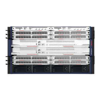
H3C CR16000-M Routers Installation Quick Start-6PW103
• This document provides a brief guide for installing H3C CR16000-M routers. For more
installation information, see H3C CR16000-M Routers Installation Guide.
• The figures in this document are for illustration only.
• The installation procedure is similar for the CR16000-M routers. The following uses a
CR16000-M8 router as an example unless otherwise specified.
• Paper manuals cannot be updated in real time with product changes.For most recent
product information,see the E-manuals at the official website.
Safety recommendations
To avoid equipment damage or bodily injury, read the following safety recommendations before
installation. Note that the recommendations do not cover every possible hazardous condition.
• Pay attention to the warnings and safety symbols on the router and operate the
router accordingly.
• Always wear an ESD wrist strap and make sure it is reliably grounded before you
install the removable components.
• Do not install the chassis, FRUs, or cables when the router is powered on.
• To avoid equipment damage or bodily injury, make sure the router is reliably grounded
before powering on the router.
• To ensure good ventilation, install a filler panel in an unused slot.
Examining the installation site
The router can be used only indoors. For the router to operate correctly and have a prolonged
service time, the installation site must meet the following requirements.
Item
Requirement
Operating: 0 to 45°C (32°F to 113°F)
Temperature
Storage: –40°C to +70°C (–40°F to +158°F)
Operating: 5% RH to 95% RH (noncondensing)
Relative
Storage: 5% RH to 95% RH (noncondensing)
humidity
• Dust buildup on the chassis might result in electrostatic adsorption, which causes poor
contact of metal components and contact points. In the worst case, electrostatic
Cleanness
adsorption can cause communication failure.
• Prevent corrosive gases from entering the installation site.
• A minimum clearance of 10 cm (3.94 in) is reserved around the inlet and outlet air vents.
Ventilation
• The rack for the router has a good cooling system.
• The installation site has a good cooling system.
• As a best practice, reserve a minimum clearance of 1 m (3.28 ft) between the rack
Space
and walls or other devices.
• Reserve enough space around the rack for cable routing.
BOM:3104A0V1
Tool list
Prepare the following installation tools yourself as required.
Flat-blade
Phillips
Needle-nose
Wire-stripping
screwdriver
screwdriver
pliers
pliers
Installation accessories
This section only lists the most commonly used installation accessories.
Grounding
Cage nut
M6 screw
cable
Installing the router
Attaching cage nuts to the rack
1. Use a pattern tool to record the installation holes of the mounting brackets and mark the
cage nut holes on the rack posts accordingly.
2. Install cage nuts on the square holes.
Installing the router in a rack
Use a minimum of two people to move the router. As a best practice, use a mechanical
lift for heavy models.
Diagonal
Claw
Marker
pliers
hammer
ESD
cable tie
Cable
wrist strap
management
bracket
Advertisement

Subscribe to Our Youtube Channel
Related Manuals for H3C CR16000-M


Summary of Contents for H3C CR16000-M
- Page 1 H3C CR16000-M Routers Installation Quick Start-6PW103 BOM:3104A0V1 Tool list • This document provides a brief guide for installing H3C CR16000-M routers. For more installation information, see H3C CR16000-M Routers Installation Guide. Prepare the following installation tools yourself as required. • The figures in this document are for illustration only.
- Page 2 Installing FRUs • Do not hold the handle of the fan tray, power module, or the rear panel of the chassis, or the air vents of chassis to carry the chassis. Any attempt to carry the router with these Installing MPUs and interface modules parts might cause equipment damage or even bodily injury.
- Page 3 Installing switching fabric modules Installing cable management brackets Before installing a switching fabric module in the chassis, make sure the connectors on the module are not broken or blocked. Removing the filler panel Installing power modules • Press the power module handle inward until it is secured in place before fastening screws.
- Page 4 Verify that the router is operating correctly by observing the LEDs on the router. For more port on the router. information about the LEDs, see H3C CR16000-M Routers Hardware Information and Specifications. Powering on the router and verifying its operation Checking before power-on •...
Need help?
Do you have a question about the CR16000-M and is the answer not in the manual?
Questions and answers