Table of Contents
Advertisement
Quick Links
Advertisement
Table of Contents

Related Manuals for Pyxis ST-725


Summary of Contents for Pyxis ST-725
- Page 2 ST-725/728 Ultra-Low Conductivity Sensors User Manual April 4, 2022 Rev. 1.04 Pyxis Lab, Inc. 1729 Majestic Dr. Suite 5 Lafayette, CO 80026 USA www.pyxis-lab.com © 2017 Pyxis Lab, Inc. Pyxis Lab Proprietary and Confidential...
-
Page 3: Table Of Contents
8 Sensor Maintenance and Precaution 8.1 Methods to Cleaning the ST-725/728 Sensor ......17... - Page 4 Pyxis Lab, Inc. Standard Limited Warranty Pyxis Lab warrants its products for defects in materials and workmanship. Pyxis Lab will, at its option, repair or replace instrument components that prove to be defective with new or remanufactured components (i.e., equivalent to new).
-
Page 5: Introduction
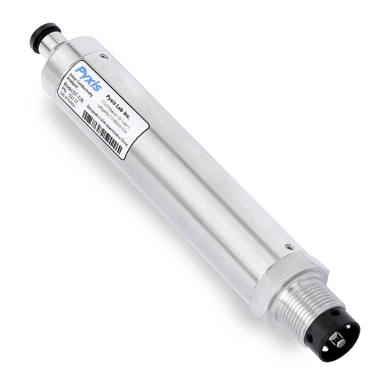
MNPT threaded installation and are constructed with a Hastelloy electrode tip and stainless-steel body. The ST-725/728 sensors can be wirelessly calibrated with uPyxis app for mobile or desktop devices when used with the MA-CR Bluetooth adapter. The sensors both offer two 4–20mA Analog outputs, one for conductiv- ity and one for temperature, as well as RS-485 Modbus output for a broad array of installations that desire to connect the smart sensor directly to receiving controller, PLC or DCS network. -
Page 6: Specifications
Remove the instrument and find the standard accessories from the shipping container as listed below. In- spect each item for any damage that may have occurred during shipping. Verify that all accessory items are included. If any item is missing or damaged, please contact Pyxis Lab Customer Service at service@pyxis- lab.com. -
Page 7: Optional Accessories
3.2 Optional Accessories The following optional accessories can be purchased via your Regional Sales contact or Pyxis Customer Service at order@pyxis-lab.com. Table 2. Optional Accessories Optional Accessory Part Number (P/N) MA-CR MA-CR (Bluetooth Adapter For uPyxis use with ST-725 / ST-728) - Page 8 The following 3 installation methods should be avoided. These installation methods can easily produce air bubbles and air accumulation leading to unstable measurement. As shown in Figure 5. Figure 5. Installation methods to be avoided ST-725/728 User Manual service@pyxis-lab.com | +1 (866) 203-8397...
-
Page 9: Wiring
4.3 Connecting via Bluetooth A Bluetooth adapter (P/N: MA-CR) can be used to connect the ST-725/728 sensor to a smart phone with the uPyxis® Mobile App or a computer with the uPyxis® Desktop App. The power should be sourced from a 24 VDC power terminal of a controller. -
Page 10: Setup And Calibration With Upyxis® Mobile App
APP for mobile or desktop devices. The ST-725 / ST-728 sensors require a slope calibration for conductivity. The conductivity can be calibrated with a standard containing 0.02 µS /cm to 200 µS /cm conductivity (depending on the sensor selected) or with the sample water itself. -
Page 11: Connecting To Upyxis® Mobile App
1. Open uPyxis® Mobile App. 2. On uPyxis® Mobile App, pull down to refresh the list of available Pyxis devices. 3. If the connection is successful, the ST-725/728 and its Serial Number (SN) will be displayed (Figure 8). 4. Press on the ST-725/728 sensor image. -
Page 12: Calibration Screen And Reading
When connected, the uPyxis® Mobile App will default to the Calibration screen. From the Calibration screen, you can perform calibrations by pressing on Slope Calibration 4-20mA Span. Follow the screen instructions for each calibration step. Figure 9. ST-725/728 User Manual service@pyxis-lab.com | +1 (866) 203-8397... -
Page 13: Diagnosis Screen
5.4 Diagnosis Screen From the Diagnosis screen, you can check the diagnosis condition. This feature may be used for technical support when communicating with service@pyxis-lab.com. Figure 10. ST-725/728 User Manual service@pyxis-lab.com | +1 (866) 203-8397... -
Page 14: Device Info Screen
5.5 Device Info Screen From the Device Info screen you can name the Device or Product and set the Modbus Address Figure 11. ST-725/728 User Manual service@pyxis-lab.com | +1 (866) 203-8397... -
Page 15: Setup And Calibration With Upyxis® Desktop App
APP for mobile or desktop devices. The ST-725 / ST-728 sensors require a slope calibration for conductivity. The conductivity can be calibrated with a standard containing 0.02 µS /cm to 200 µS /cm conductivity (depending on the sensor selected) or with the sample water itself. -
Page 16: Connecting To Upyxis® Desktop App
3. On uPyxis® Desktop App, click Device Connect via USB-Bluetooth (Figure 13). 4. If the connection is successful, the ST-725/728 and its Serial Number (SN) will be displayed in the left pane of the uPyxis® window. NOTE After the sensor and Bluetooth is powered up, it may take up to 10 seconds for the adapter to establish the wireless signal for communication. -
Page 17: Information Screen
To calibrate the device, click on Calibration. On the Calibration screen there are two calibration buttons, Slope Calibration 4-20mA Span. The screen also displays the reading of the device. The reading refresh rate is every 4 seconds. Follow the screen instructions for each calibration step. Figure 16. ST-725/728 User Manual service@pyxis-lab.com | +1 (866) 203-8397... -
Page 18: Diagnosis Screen
Figure 17. 7 Outputs 7.1 4–20mA Output Setup The 4–20mA output of the ST-725 sensor is scaled as: • Conductivity: – 4 mA = 0 µS/cm – 20 mA = 200 µS/cm •... -
Page 19: Adjusting 4-20Ma Span
Figure 19. 7.3 Communication using Modbus RTU The ST-725/728 sensor is configured as a Modbus slave device. In addition to the µS/cm conductivity value, many operational parameters, including warning and error messages, are available via a Modbus RTU con- nection. Contact Pyxis Lab Customer Service (service@pyxis-lab.com) for more information. -
Page 20: Sensor Maintenance And Precaution
Figure 20. Inline Probe Cleaning Solution Kit To clean the ST-725/728 sensor, soak the lower half of the sensor in 100 ml of in-line sensor cleaning solution for 10 minutes or longer (the cleaning solution should completely submerge the front e lectrode). After soaking, gently scrub the electrode surface with a cotton s wab.
Need help?
Do you have a question about the ST-725 and is the answer not in the manual?
Questions and answers