
Related Manuals for Pyxis ST-600


Summary of Contents for Pyxis ST-600
- Page 1 ST-600 Inline Bleach Concentration Monitoring Probe Operational Manual Version 1.2 October 2018...
-
Page 2: Table Of Contents
6.5. Connecting to Device 6.6. Diagnosis Screen 6.7. Calibrating Device 6.8. Zero Calibration 6.9. Slope Calibration 6.10. 4-20mA Span 7. Calibration on the Controller 8. Communicating using Modbus RTU 9. Probe Cleaning and Maintenance 10. How to Clean ST-600 Probe... - Page 3 Pyxis Lab, Inc. Standard Limited Warranty Pyxis Lab warrants its products for defects in materials and workmanship. Pyxis Lab will, at its option, repair or replace instrument components that prove to be defective with new or remanufactured components (i.e., equivalent to new).
-
Page 4: Introduction
The wet part of the probe is a 6-inch long, 7 mm OD Teflon tubing. This configuration ensures long-term stable measurement of the bleach concentration. The ST-600 probe can be connected to any device that accepts an isolated or non-isolated 4-20mA input. Other features of the Pyxis ST-600 probe include: •... -
Page 5: Specifications
3. Specification • Power Supply Required: 24 (±2) VDC @ 65 mA • Signal Output: 4-20 mA and RS-485 Modbus RTU • Temperature, Sample Water: 40 – 104 °F (4 – 40 °C) • Temperature, Ambient during operation: 40 – 120 °F (4 – 49 °C) •... -
Page 6: Quick 4-20Ma Start
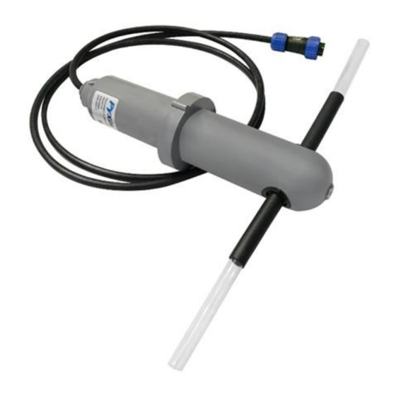
Figure 1. ST-600 Bleach Concentration Probe 4.1. Quick 4-20mA Start Note: The negative 24V power terminal (power ground) and the negative 4-20 mA terminal on the ST- 600 probe are internally connected. If the power ground terminal and the negative 4-20 mA terminal in the controller are internally connected (non-isolated 4-20mA input), it is unnecessary to connect the 4-20 mA negative wire (blue) to the 4-20 mA negative terminal in the controller. -
Page 7: Connect Via Usb
Connect via WiFi/Bluetooth Figure 2 shows the connection between a computer and the ST-600 probe via WiFi/Bluetooth adapter (P/N: MA-WB). A smart phone app is provided to connect the ST-600 probe to your smart phone via WiFi or Bluetooth interface. -
Page 8: Connect Via Wifi/Bluetooth
4.3. Connect via USB Figure 3 shows the connection between a computer and the ST-600 probe via USB-RS485 adapter. Use the USB-RS485 adapter provided by Pyxis Lab Inc. (Item Number: MA-485). Using other USB-485 adapters may result in permanent damage of the ST-600 probe communication hardware. -
Page 9: Connected To Upyxis Mobile App
5.2. Connecting to uPyxis Mobile App Turn on Bluetooth on your mobile phone (Do not pair the phone Bluetooth to the ST-600). Open uPyxis Mobile App. uPxis App connects to the Probe and click on the ST-600 probe. 5.3. Calibration Screen and Reading... -
Page 10: Diagnosis Screen
5.4. Diagnosis Screen From the Diagnosis screen. You can check the Diagnosis Condition, and Export & Upload. 5.5. Device Info Screen From the Device Info screen. You can name the Device or Product. -
Page 11: Probe Calibration With Upyxis Desktop App
6. Probe Calibration with uPyxis Desktop App 6.1. Download uPyxis Desktop App Download uPyxis Desktop App from https://pyxis-lab.com/support-2/... -
Page 12: Unzip Upyxis Desktop App
6.2. UnZip uPyxis Desktop App Find your downloaded uPyxis Setup 1.3.8 file, Right Click on the file, Extract All, and then Extract. -
Page 13: Installing Upyxis Desktop App
6.3. Installing uPyxis Desktop App Once the uPyxis Desktop App has been extracted. Find the extracted uPyxis Setup file and left click, click on Run, and then click Install. After install has been clicked the Setup Progress will continue. Follow the step during installation process. -
Page 14: Connecting Upyxis Desktop App
6.4. Connecting to uPyxis Desktop App Open uPyxis Desktop App on your desktop. When the desktop app opens, to find your device, click on Device, then Connect via WiFi. -
Page 15: Connecting To Device
6.5. Connecting to Device When connected via WiFi, in the Discovered Devices box there will be the device product name (If no device product name in the Discovered Devices box, click Refresh). If device product name shows in the box, then click on Connect to Device. -
Page 16: Diagnosis Screen
6.6. Diagnosis Screen After the device has been calibrated and installation has been completed. To check diagnosis, click on Diagnosis. When in the Diagnosis screen you can view the Diagnosis Condition of the device. 6.7. Calibrating Device To calibrate the device, click on Calibration. On the Calibration screen there are three calibration tabs, Zero Calibration, Slope... -
Page 17: Zero Calibration
6.8. Zero Calibration To perform Zero Calibration, click on Zero Calibration. Then follow the instruction on how to calibrate, then click 6.9. Slope Calibration To perform Slope Calibration, click on Slope Calibration. Then follow the instruction on how to calibrate, then click Slope Calibration. -
Page 18: 4-20Ma Span
8. Communicating using Modbus RTU The ST-600 probe is configured as a Modbus slave device. In addition to the NTU value, many operational parameters, including warning and error messages, are available via a Modbus RTU connection. -
Page 19: Probe Cleaning And Maintenance
It is rare that the probe Teflon tubing needs to be cleaned or replaced. However, a replacement tubing with the proper socket fitting to fix the tubing to the probe body can be purchased from Pyxis. It is recommended that the ST-600 probe is calibrated monthly with using DI and a bleach standard solution.
Need help?
Do you have a question about the ST-600 and is the answer not in the manual?
Questions and answers