
Related Manuals for Pyxis ST-500


Summary of Contents for Pyxis ST-500
- Page 1 ST-500 Inline PTSA Fluorometer Probe Operation Manual Rev. B Pyxis Lab, Inc. 1729 Majestic Dr. Suite 5 Lafayette, CO 80026 USA www.pyxis-lab.com © 2017 Pyxis Lab, Inc. Pyxis Lab Proprietary and Confidential...
- Page 2 Device Warranty Term The Pyxis warranty term for the ST-500 probe is thirteen (13) months from original shipment from Pyxis. In no event shall the standard limited warranty coverage extend beyond thirteen (13) months from original shipment date.
-
Page 3: Table Of Contents
Table of Contents Introducing the Pyxis ST-500 Probe .....................4 Features of the Pyxis ST-500 ......................4 Specifications ..........................5 Unpacking the Pyxis ST-500 ......................5 Standard Accessories ........................5 Optional Accessories ........................5 Installation ..........................6 Quick 4-20mA Start ........................6 Calibration and Diagnosis......................7 Calibration and Diagnosis by uPyxis Mobile App ................ -
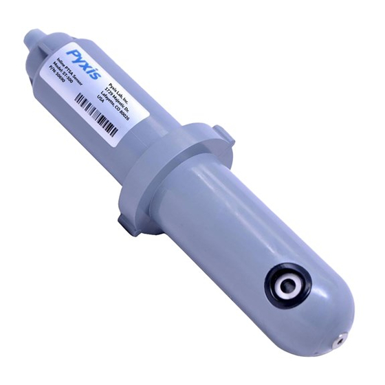
Page 4: Introducing The Pyxis St-500 Probe
The 4-20mA current output of the ST-500 probe can be connected to any controller that accepts an isolated or non-isolated 4-20mA input. The ST-500 probe is a smart device. In addition to measuring fluorescence, the ST-500 probe has extra photo-electric components that monitor the color and turbidity of the sample water. -
Page 5: Specifications
Remove the instrument and accessories from the shipping container and inspect each item for any damage that may have occurred during shipping. Verify that all items listed on the packing slip are included. If any items are missing or damaged, please contact Pyxis Customer Service at service@pyxis- lab.com. -
Page 6: Installation
2 Installation Place the O-ring into the O-ring grove in the tee. Insert the ST-500 probe into the tee. The tee can be connected to a pipe system through the ¾ inch straight socket or thread socket, both included in the package. -
Page 7: Calibration And Diagnosis
Tap the discovered ST-500 probe to connect to the probe. uPyxis app can identify the probe type if multiple Pyxis probes are discovered in the scan. For legacy old generation probes, a dialog message window will be displayed to ask the user to tell the app the probe type. In case, please select ST-500. Pyxis ST-500... -
Page 8: Calibration By Upyxis Mobile App
As shown in figure 4, the calibration page after uPyxis is connected to the probe via the Pyxis Bluetooth adapter displays the current PTSA value. Three functional tabs are available in this page: Zero Calibration, Slope Calibration, and 4-20mA Span. -
Page 9: Diagnosis
Figure 6. Enter PTSA concentration to set 4-20mA 4.1.3 Diagnosis Tap Diagnosis in the bottom of the app page to launch the diagnosis page (figures 7 and 8). Figure 7. Select diagnosis condition Figure 8. Cleanliness check result and raw data Pyxis ST-500 Operation Manual... -
Page 10: Calibration And Diagnosis By Upyxis Desktop App
Download and install uPyxis desktop app from www.pyxis-lab.com/support-2/. Connect and power the ST-500 probe to a computer via the Pyxis USB-RS485 adapter according to connection diagram below. Use the USB-RS485 adapter provided by Pyxis Lab Inc. (Item Number: MA-485). Using other USB-485 adapters may result in permanent damage of the ST-500 probe communication hardware. - Page 11 Figure 8. Connection Options Figure 9. Select a Comm port Pyxis ST-500 Operation Manual...
-
Page 12: Calibration
Figure 10. Connected to a ST-500 probe and information page Figure 11. Calibration page 4.2.1 Calibration Click Calibration to launch the calibration page (figure 13). Place the probe in deionized water and click Zero Calibration to carry out the zero-point calibration. -
Page 13: 4-20Ma Span
If the probe is severely fouled, a red Fouled message will be shown. In this case, please clean the probe according to the procedure in Section 6 of this manual. Figure 12. Enter PTSA concentration for slope calibration Pyxis ST-500 Operation Manual... - Page 14 Figure 13. Set 4-20mA span Figure 14. Select diagnosis condition before cleanliness check Pyxis ST-500 Operation Manual...
-
Page 15: Calibration On The Controller
5 Modbus RTU The ST-500 probe is configured as a Modbus slave device. In addition to the ppb PTSA value, many operational parameters, including warning and error messages, are available via a Modbus RTU connection. -
Page 16: Probe Cleaning And Maintenance
Soak the lower half of the ST-500 probe in 100 ml inline probe cleaning solution for 30 minutes. Rinse the ST-500 probe with distilled water and then check for the flashing blue light inside the ST-500 probe quartz tube. If the surface is not entirely clean, continue to soak the ST-500 probe for an additional 30 minutes. -
Page 17: Other Common Troubleshooting Issues
Section 4 of this manual. 6.2 Other Common Troubleshooting Issues If the ST-500 probe output signal is not stable and fluctuates significantly, make an additional solution ground connection – connect the clear solution ground wire to a conductor that contacts the sample water electrically such as a brass pipe adjacent to the ST-500 tee.
Need help?
Do you have a question about the ST-500 and is the answer not in the manual?
Questions and answers