Table of Contents
Advertisement
Quick Links
Advertisement
Table of Contents

Subscribe to Our Youtube Channel
Related Manuals for Pyxis ST-525


Summary of Contents for Pyxis ST-525
- Page 2 ST-525 Series Inline Fluorescein Fluorometer Sensors User Manual January 22, 2021 Rev. 1.00 Pyxis Lab, Inc. 1729 Majestic Dr. Suite 5 Lafayette, CO 80026 USA www.pyxis-lab.com © 2017 Pyxis Lab, Inc. Pyxis Lab Proprietary and Confidential...
-
Page 3: Table Of Contents
8 Sensor Maintenance and Precaution 8.1 Methods to Cleaning the ST-525 Series Sensor ......20 8.2 Storage . - Page 4 Pyxis Lab, Inc. Standard Limited Warranty Pyxis Lab warrants its products for defects in materials and workmanship. Pyxis Lab will, at its option, repair or replace instrument components that prove to be defective with new or remanufactured components (i.e., equivalent to new).
-
Page 5: Introduction
The ST-525 Series sensor is easy to calibrate using the uPyxis® Mobile or Desktop App. Any standard con- taining Fluorescein in the range of 10 to 60 ppb can be used for the calibration of the ST-525 SeriesṪ h e standard may also be the water sample itself if the Fluorescein concentration of the sample is measured and validated by a calibrated offline fluorometer. -
Page 6: Specifications
Up to 100 psi (0.7 MPa) (65 °C) Enclosure Rating IP67 Regulation With Pyxis’s continuous improvement policy, these specifications are subject to change without notice. † See Figure 3 for ST-525SS dimensions. ST-525 Series User Manual service@pyxis-lab.com | +1 (866) 203-8397... -
Page 7: Unpacking Instrument
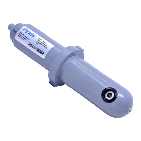
• 7-Pin Female Adapter/Flying Leads Cable (2 ft) P/N: MA-1100 • User Manual available online at https://pyxis-lab.com/support/ 3.2 Optional Accessories The following optional accessories can be ordered from Pyxis Customer Service (order@pyxis-lab.com) or Pyxis E-Store at https://pyxis-lab.com/shop/. Figure 1. ST-525 Series User Manual service@pyxis-lab.com... -
Page 8: Installation
4.1 ST-525 Piping The provided ST-001 Tee Assembly can be connected to a pipe system through the 3/4” female ports, either socket or NPT threaded. To properly install the ST-525 sensor into the ST-001 Tee Assembly, follow the steps below: 1. -
Page 9: St-525Ss Piping
°F (49 °C). The sensor can be held by a 1.75-inch pipe clamp or mounted to a panel with four 1/4-28 bolts. See Figure 3 for ST-525SS dimensions. Figure 3. Dimension of the ST-525SS (inch) ST-525 Series User Manual service@pyxis-lab.com | +1 (866) 203-8397... -
Page 10: Wiring
NOTE The negative 24V power terminal (power ground) and the negative 4–20mA ter- minal on the ST-525 Series sensor are internally connected. Follow the wiring table below to connect the ST-525 Series sensor to a controller: Table 2. Wire Color... -
Page 11: Connecting Via Bluetooth
4.4 Connecting via Bluetooth A Bluetooth adapter (P/N: MA-WB) can be used to connect a ST-525 Series sensor to a smart phone with the uPyxis® Mobile App or a computer with a Bluetooth/USB Adapter (P/N: MA-NEB) and the uPyxis® Desktop App. -
Page 12: Setup And Calibration With Upyxis® Mobile App
5 Setup and Calibration with uPyxis® Mobile App The ST-525 Series sensor can be calibrated in a two-point (zero + slope) procedure using a deionized (DI) water sample and a standard containing 10 to 60 ppb Fluorescein. The calibration solution could be the sample water itself. -
Page 13: Connecting To Upyxis® Mobile App
1. Open uPyxis® Mobile App. 2. On uPyxis® Mobile App, pull down to refresh the list of available Pyxis devices. 3. If the connection is successful, the ST-525 Series and its Serial Number (SN) will be displayed (Figure 4. Press on the ST-525 Series sensor image. -
Page 14: Calibration Screen And Reading
When connected, the uPyxis® Mobile App will default to the Calibration screen. From the Calibration screen, you can perform calibrations by pressing on Zero Calibration, Slope Calibration, and 4-20mA Span. Follow the screen instructions for each calibration step. Figure 8. ST-525 Series User Manual service@pyxis-lab.com | +1 (866) 203-8397... -
Page 15: Diagnosis Screen
If the sensor is severely fouled, a Dirty message will be shown. In this case, follow the procedure in the Methods to Cleaning the ST-525 Series Sensor section of this manual. Figure 9. ST-525 Series User Manual service@pyxis-lab.com... -
Page 16: Device Info Screen
5.5 Device Info Screen From the Device Info screen. You can name the Device or Product. Figure 10. ST-525 Series User Manual service@pyxis-lab.com | +1 (866) 203-8397... -
Page 17: Setup And Calibration With Upyxis® Desktop App
6 Setup and Calibration with uPyxis® Desktop App The ST-525 Series sensor can be calibrated in a two-point (zero + slope) procedure using a deionized (DI) water sample and a standard containing 10 to 60 ppb Fluorescein. The calibration solution could be the sample water itself. -
Page 18: Connecting To Upyxis® Desktop App
Connect via USB-RS485 (Fig- ure 12). 4. If the connection is successful, the ST-525 Series and its Serial Number (SN) will be displayed in the left pane of the uPyxis® window. NOTE After the sensor and Bluetooth is powered up, it may take up to 10 seconds for the adapter to establish the wireless signal for communication. -
Page 19: Information Screen
Calibration, and 4-20mA Span. The screen also displays the reading of the device. The reading refresh rate is every 4 seconds. Follow the screen instructions for each calibration step. Figure 14. ST-525 Series User Manual service@pyxis-lab.com | +1 (866) 203-8397... -
Page 20: Diagnosis Screen
Check. If the sensor is clean, a green Clean message will be shown. If the sensor is severely fouled, a red Dirty message will be shown. In this case, follow the procedure in the Methods to Cleaning the ST-525 Series Sensor section of this manual. Figure 15. -
Page 21: Adjusting 4-20Ma Span
Figure 17. 7.3 Communication using Modbus RTU The ST-525 Series sensor is configured as a Modbus slave device. In addition to the ppb Fluorescein value, many operational parameters, including warning and error messages, are available via a Modbus RTU con- nection. -
Page 22: Sensor Maintenance And Precaution
ST-525 Series sensor is used as part of an auto- mated control system. When used to control product dosing, it is suggested that the automation system be configured to provide backup to limit potential product overfeed, for example by limiting pump size or duration, or by alarming if the pumping rate exceeds a desired maximum limit. -
Page 23: Methods To Cleaning The St-525 Series Sensor
Figure 18. Inline Probe Cleaning Solution Kit To clean the ST-525 Series sensor, soak the lower half of the sensor in 100 mL inline sensor cleaning solution for 30 minutes. Rinse the ST-525 Series sensor with distilled water and then check for the flashing blue light inside the ST-525 Series sensor quartz tube. -
Page 24: Contact Us
10 Contact Us Pyxis Lab, Inc 1729 Majestic Dr. Suite 5 Lafayette, CO 80026 USA www.pyxis-lab.com Phone: +1 (866) 203-8397 Email: service@pyxis-lab.com ST-525 Series User Manual service@pyxis-lab.com | +1 (866) 203-8397...
Need help?
Do you have a question about the ST-525 and is the answer not in the manual?
Questions and answers