Titan Logix TD100 Installation Manual
Hide thumbs
Also See for TD100:
- Installation & operation manual (80 pages) ,
- Programming and configuration manual (18 pages) ,
- Operating (3 pages)
Table of Contents
Advertisement
Quick Links
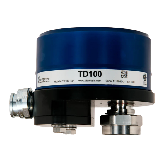
Transmitter
Coaxial Probe
Dual Rod Probe
The TD100 system must be installed and operated in accordance with
the details described in the Titan Logix manuals, application notes, and
all other relevant publications.
Only qualified personnel familiar with the installation and operation of this
equipment should install, adjust, operate, or service this equipment.
Failure to observe these instructions could result in bodily injury or loss of
life.
Step 2
Install the Anchor Cone, pg. 2
Step 3
Step 4
Offset Measurement, pg. 4
Step 5
Mount the Transmitter, pg. 4
Step 6
Mount the Finch II Display, pg. 5
Step 7
Connect Vehicle Power, pg. 7
Step 8
Connect TD100 to Finch II, pg. 7
Step 9
Enable Remote Display, pg. 8
www.titanlogix.com
TD100
Installation Guide
Page 1
Advertisement
Table of Contents

Subscribe to Our Youtube Channel
Related Manuals for Titan Logix TD100


Summary of Contents for Titan Logix TD100
- Page 1 TD100 Installation Guide The TD100 system must be installed and operated in accordance with the details described in the Titan Logix manuals, application notes, and all other relevant publications. Only qualified personnel familiar with the installation and operation of this equipment should install, adjust, operate, or service this equipment.
- Page 2 Ensure all required tools are available for installation. Refer to the TD100 Installation & Operation Manual (TPM 057), and the Finch II Installation & Operation Manual (TD010) to view detailed procedures of any steps outlined in this Quick Reference Guide.
- Page 3 TD100 Installation Guide Install the Probe (Coaxial or Dual Rod) a. Cut the probe to length. i Dual rod probes are measured from the top of the collar to the bottom of the cone/bracket. Add 1.5” to calculate the accurate cut length of the probe (Cut Length = Tank Height + 1.5”).
- Page 4 TD100 Installation Guide Offset Measurement Before installing the probe, measure the Tank Thickness using a suitable device with 1mm accuracy. Save this measurement for further calculation. After installing the probe, measure the Probe Offset distance Offset Distance - Without Riser...
- Page 5 TD100 Installation Guide Mount the Finch II Display Attach the mounting tabs to the back of the Finch display as shown in the figure “Finch II Mounting Tabs”. Mount the Finch II, ensuring that the unit is: Installed in a location that does not exceed Class 1, Div. 2 area classification.
- Page 6 Observe the following instructions during installation: Wire splices should be made inside a weatherproof enclosure or junction box to prevent premature failure due to corrosion. The TD100 transmitter terminal wiring area forms an explosion-proof enclosure. Care must be taken when opening or closing the enclosure.
- Page 7 TD100 cable to the Finch II. Insert wires from the explosion-proof elbow into the 1/2” thread for the connector and tighten the union nut on the TD100 (see top view). Pull the cable through strain relief on the Finch II and tighten the strain relief until the cable is secure.
- Page 8 TD100 system. In the event error messages are observed when applying power to the system, refer to the Troubleshooting section of the TD100 Installation & Operation Manual (TPM 057). www.titanlogix.com...
Need help?
Do you have a question about the TD100 and is the answer not in the manual?
Questions and answers