
Subscribe to Our Youtube Channel
Related Manuals for Titan Logix Rack Control Module


Summary of Contents for Titan Logix Rack Control Module
- Page 1 RACK CONTROL ™ MODULE INTERFACE DEVICE FOR CONNECTING TD80 GAUGING SYSTEMS TO THERMISTOR AND OPTIC STYLE LOADING RACKS *Also available in an optic-only model PRODUCT MANUAL TPM 007 Revision 1.2...
- Page 2 Alberta and/or Lampman, Saskatchewan and/ or Overland Park, Kansas. Should repair be required, freight will only be covered by Titan Logix Corp. for the cost of the return of the repaired product to the customer. All other freight charges will be incurred by the customer.
-
Page 3: Table Of Contents
TD80 System Specific Troubleshooting ..............32 TD80 and RCM Intermittent Circuit Troubleshooting ..........40 Technical Reference ....................42 Rack Control Module Kit Components: ..............42 Specifications: ...................... 42 Index of Figures Figure 1-1: Dual Rod Probe Truck & Trailer Installation .............7 Figure 1-2: Coaxial Probe Truck &... -
Page 4: Introduction
Technical Specification. Disclaimer The information in this document is subject to change without notice. Titan Logix Corp. makes no representations or warranties with respect to the contents hereof. Only qualified personnel should install this product. Please read this manual before installing this product and follow all applicable safety and electrical regulati ons as required. -
Page 5: Introduction And Description
Rack Control Module Product Manual Introduction and Description 1.3.1 System Description The RCM is part of a secondary overfill prevention system. It is an optional accessory that receives alarm information from the TD80 level transmitter, providing overfill information to industry standard 5-wire optic and 2-wire thermistor terminal rack controllers. -
Page 6: Td80 System Components
Rack Control Module Product Manual 1.3.3 TD80 System Components TD80 Transmitter The TD80 transmitter generates and processes the GWR signals to determine liquid level in a tank. The TD80 is mounted on the tank top and connected to the probe, is weatherproof and rated for use in hazardous locations where explosive fumes may be present. -
Page 7: The Td80 Alarm System
Rack Control Module Product Manual Finch Relay Module The Finch Relay Module is an accessory that enables overfill prevention by control of an onboard pump or loading valve. Horns and Lights Alarm reporting is through optional vehicle mounted horns and lights. -
Page 8: Graphical Glossary Of Terms
Rack Control Module Product Manual Graphical Glossary of Terms Dual Rod Probe Truck and Trailer Installation Figure 1-1: Dual Rod Probe Truck & Trailer Installation Rev. 1.2, May 9, 2014 Page 7... -
Page 9: Figure 1-2: Coaxial Probe Truck & Trailer Installation
Rack Control Module Product Manual Coaxial Probe Truck and Trailer Installation Figure 1-2: Coaxial Probe Truck & Trailer Installation Rev. 1.2, May 9, 2014 Page 8... -
Page 10: Operation
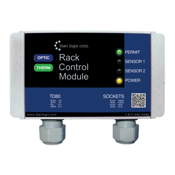
The RCM does not have any operator controls. It receives all information and control from the TD80 transmitter. Loading permit status and diagnostic information is provided by four indicator lights, as shown below. Figure 2-1: Rack Control Module Indicators Purpose... -
Page 11: Sequence Of Events
Rack Control Module Product Manual The following table describes a normal sequence of events for loading and unloading the tanker. Included is the RCM response to system failures. The principal concept of RCM operation is to deny loading until all conditions are safe. Then the terminal rack controller receives a signal to permit loading. -
Page 12: Table 2-2: Sequence Of Events
Rack Control Module Product Manual Permissive Signal to the Event Sequence - Inputs Terminal Rack Power Sensor 1 Sensor 2 Permit are Battery Power and Controller OFF is Indicator Indicator Indicator Indicator TD80 Data Loading Denied, ON is Permitted Normal Operating Conditions 10. -
Page 13: Installation
Rack Control Module Product Manual 3 Installation TD80 Installation Steps Overview The following installation instructions are specific to the RCM only. Refer to the TD80 Installation and Operation Manual, TPM 001 for full TD80 Level Gauging and Overfill Prevention System details. - Page 14 Rack Control Module Product Manual * The following installation instructions provide detail for steps 8, 10, 16 and 17 in the table above. Refer to the TD80 Installation and Operation Manual, TPM 001 for full TD80 Level Gauging and Overfill Prevention System installation steps 1 through 17 Step 8: Mount the Alarm Accessories, Including the RCM 1.
-
Page 15: Figure 3-1: Wiring For Standard Api Optic And Thermistor Sockets
Rack Control Module Product Manual Figure 3-1: Wiring For Standard API Optic and Thermistor Sock ets Rev. 1.2, May 9, 2014 Page 14... -
Page 16: Figure 3-2: Wiring For Standalone J560 7-Pin Optic Socket
Rack Control Module Product Manual Figure 3-2: Wiring For Standalone J560 7-Pin Optic Sock et Rev. 1.2, May 9, 2014 Page 15... -
Page 17: Figure 3-3: Wiring For Optic Api Socket And Rcm -J560 Optic Socket
Rack Control Module Product Manual Figure 3-3: Wiring For Optic API Sock et and RCM-J560 Optic Sock et Rev. 1.2, May 9, 2014 Page 16... -
Page 18: Figure 3-4: Wiring For Standard Api Optic And Thermistor Sockets And Rcm-J560 Optic Socket
Rack Control Module Product Manual Figure 3-4: Wiring For Standard API Optic and Thermistor Sock ets and RCM-J560 Optic Sock et Rev. 1.2, May 9, 2014 Page 17... -
Page 19: Figure 3-5: Td80 And Rcm Interconnection (No Junction Box), Single Installations, Wiring Schematic
Rack Control Module Product Manual Figure 3-5: TD80 and RCM Interconnection (no Junction Box), Single Installations, Wiring Schematic Rev. 1.2, May 9, 2014 Page 18... -
Page 20: Figure 3-6: Td80 And Rcm Interconnection (No Junction Box), Single Installations, Wiring Diagram
Rack Control Module Product Manual Figure 3-6: TD80 and RCM Interconnection (no Junction Box), Single Installations, Wiring Diagram Rev. 1.2, May 9, 2014 Page 19... -
Page 21: Figure 3-7: Td80 And Rcm Interconnection, Single Installation, Wiring Schematic
Rack Control Module Product Manual Figure 3-7: TD80 and RCM Interconnection, Single Installation, Wiring Schematic Rev. 1.2, May 9, 2014 Page 20... -
Page 22: Figure 3-8: Td80 And Rcm Interconnection, Single Installation, Wiring Diagram
Rack Control Module Product Manual Figure 3-8: TD80 and RCM Interconnection, Single Installation, Wiring Diagram Rev. 1.2, May 9, 2014 Page 21... -
Page 23: Figure 3-9: Td80 And Rcm Interconnection, Dual Installation (2X Single Displays), Wiring Schematic
Rack Control Module Product Manual Figure 3-9: TD80 and RCM Interconnection, Dual Installation (2x Single Displays), Wiring Schematic Rev. 1.2, May 9, 2014 Page 22... -
Page 24: Figure 3-10: Td80 And Rcm Interconnection, Dual Installation (2X Single Displays), Wiring Diagram
Rack Control Module Product Manual Figure 3-10: TD80 and RCM Interconnection, Dual Installation (2x Single Displays), Wiring Diagram Rev. 1.2, May 9, 2014 Page 23... -
Page 25: Table 3-2: System Test And Verification Checklist
Rack Control Module Product Manual Step 16: Perform the TD80 Overfill Prevention System Test and Verification Each TD80 system installed on the tanker is to be tested by the following procedure. For two compartment tankers, steps 1 through 7 must be repeated for each TD80 and Finch. - Page 26 Rack Control Module Product Manual i. Power Indicator is ON and solid YELLOW ii. Sensor #1 and #2 are OFF iii. Permit is ON and solid GREEN 1. If the Permit is SOLID RED , turn the power OFF and then back ON 3.
- Page 27 Rack Control Module Product Manual iii. Installed onboard overfill prevention system activates iv. RCM Indicators are as follows: 1. Power Indicator is ON and solid YELLOW 2. Sensor #1 or #2 is solid RED for the compartment being tested 3. Permit is ON and solid RED g.
- Page 28 Rack Control Module Product Manual NOTE: The TD80 system has now been thoroughly tested. The next step is to confirm correct operation of the RCM and sockets. A Universal Truck Tester (UTT) is requi red to test correct operation of the installed 5-wire Optic and/or 2-wire Thermistor socket(s).
-
Page 29: Figure 3-11: Sample Depth Chart
Rack Control Module Product Manual Step 17: Offset Calibration Description Sample Depth Chart, 206bbl trailer, 81” depth Offset calibration of the TD80 transmitter is required after installation, programming or replacement of the TD80 transmitter. The calibration compensates for 0.05 variations from the calibration chart provided by the tank manufacturer and probe mounting height above the tank top. - Page 30 Rack Control Module Product Manual then the current volume measured by the TD80. This should be close to the actual volume. g. Use the Up and/or Down buttons to adjust the displayed volume to the actual amount. Then release the buttons.
- Page 31 Rack Control Module Product Manual 3. Offset Calibration Using a Measured Level See Figure 3-11 sample depth chart for the following calibration step examples. a. Fill the tank approximately 3/4 full. Determine the volume by dipping and referring to a depth chart. An alternative is to place a wire short at a level 1/2 to 2/3 of the probe depth in an empty tank.
-
Page 32: Troubleshooting
Rack Control Module Product Manual 4 Troubleshooting The following troubleshooting instructions are specific to the RCM only. Refer to the TD80 Installation and Operation Manual, TPM 001 for full TD80 Level Gauging and Overfill Prevention System details. The RCM may be installed in any currently recommended TD80 system including one that performs onboard loading control. -
Page 33: Td80 System Specific Troubleshooting
Rack Control Module Product Manual 6. Defective electrical component such as connector, switch, plug, socket, terminal strip or junction box 3. Confirm presence of an open circuit in wiring An open circuit in wiring may be confirmed after testing by temporarily bridging the break with a short length of wire bared at both ends or a jumper with alligator clips. - Page 34 These are some of the most common system wiring and component failures along with suggested troubleshooting and repair steps. As an alternative, please also refer to the pictorial Rack Control Module Operator Guide for loading, unloading, alarm and error conditions.
- Page 35 Rack Control Module Product Manual Symptom 1: Terminal rack controller does not permit loading. A NON- PERMISSIVE signal is always sent to the terminal rack controller. Confirm with a UTT. For Single or Dual TD80 Systems: Permit: OFF Sensor 1: OFF...
- Page 36 Rack Control Module Product Manual For Single or Dual TD80 Systems: Permit: BLINKING ORANGE Sensor 1: BLINKING ORANGE Sensor 2: BLINKING ORANGE Power: BLINKING ORANGE WHAT TO DO: DETAILS: WHAT TO CHECK: REMEDY: Check Poor or no Check for 1. Inspect RCM wiring...
- Page 37 Rack Control Module Product Manual For Single or Dual TD80 Systems: Permit: RED Sensor 1: RED Sensor 2: OFF Power: SOLID YELLOW WHAT TO DO: DETAILS: WHAT TO CHECK: REMEDY: Check the Finch Clear the alarm If the alarm 1. Check for loose...
- Page 38 Rack Control Module Product Manual For Single or Dual TD80 Systems: Permit: RED Sensor 1: OFF Sensor 2: RED Power: SOLID YELLOW WHAT TO DO: DETAILS: WHAT TO CHECK: REMEDY: Check the Finch Clear the alarm If the alarm 1. Check for loose...
- Page 39 Rack Control Module Product Manual Symptom 2: Terminal rack controller does not deny loading. A PERMISSIVE signal is always sent to the terminal rack controller. Confirm with the UTT. For Single or Dual TD80 Systems: Permit: RED Sensor 1: OFF...
- Page 40 Rack Control Module Product Manual Symptom 3: Terminal rack controller halts loading before expected. HH alarm shuts down loading prematurely. Finch display shows flashing “HH” and loaded volume for the affected compartment. For Single or Dual TD80 Systems: Permit: RED...
-
Page 41: Td80 And Rcm Intermittent Circuit Troubleshooting
Rack Control Module Product Manual TD80 and RCM Intermittent Circuit Troubleshooting Diagnosing and repairing a problem that comes and goes is one of the most challenging situations to troubleshoot. Sometimes the problem only affects one part of a system or seeming random things happen everywhere. - Page 42 Rack Control Module Product Manual i. Check all electrical wiring and connections between the affected transmitter and display. ii. If this happens while a two-way radio is keyed, find and physically separate all TD80/Finch and radio wiring. 3. Intermittent RCM Permissive. Permit light changes from green to red and back to green intermittently.
-
Page 43: Technical Reference
Rack Control Module Product Manual 5 Technical Reference Rack Control Module Kit Components: Rack Control Module Dual sockets with built-in ground bolt Thermistor 6-Way Dummy and Optical Booster Optic-only model does not include thermistor socket with dummy) ... - Page 44 Manufactured in Canada Manufactured by: Head Office Saskatchewan Branch Kansas Branch 4130 – 93 Street Box 460 103 Cenaiko Street 8900 Nieman Road Edmonton, Alberta Lampman, Saskatchewan Overland Park, Kansas Canada T6E 5P5 Canada S0C 1N0 USA 66214 P 780.462.4085 P 306.487.2883 P 913.541.8200 F 780.450.8369...
Need help?
Do you have a question about the Rack Control Module and is the answer not in the manual?
Questions and answers
Where do I put the viecal id wire too?