
Subscribe to Our Youtube Channel
Related Manuals for vacuubrand VACUU-PURE 10C


Summary of Contents for vacuubrand VACUU-PURE 10C
- Page 1 Vacuum pump VACUU·PURE 10C Instructions for use Original instructions EN OI no.: 20901224...
- Page 2 +49 9342 808‑5660 Fax: +49 9342 808‑5555 Email: info@vacuubrand.com Web: www.vacuubrand.com Thank you for purchasing this product from VACUUBRAND GMBH + CO KG VACUUBRAND GMBH + CO KG. You have chosen a modern and technically high quality product. 20901224_EN_VACUU·PURE 10C_V1.8_221122...
-
Page 3: Table Of Contents
Contents TABLE OF CONTENTS Introduction User information ....... . . 5 1.2 About this document. - Page 4 Contents Commissioning (operation) 5.1 Switch on ........44 5.2 Operation .
-
Page 5: Introduction
Copyright The content of this manual is protected by copyright. Only copies Copyright © and copyright law for internal use are allowed, e.g., for professional training. © VACUUBRAND GMBH + CO KG © VACUUBRAND GMBH + CO KG 20901224_EN_VACUU·PURE 10C_V1.8_221122... -
Page 6: About This Document
Contact us ƒ replacement. Alternatively, you can use our download portal: www.vacuubrand.com You are welcome to contact us at any time in writing or by ƒ telephone if you would like more information, have questions about our products or wish to share feedback with us. -
Page 7: Display Conventions
Introduction 1.2.2 1.2.2 Display conventions Display conventions Warning levels DANGER DANGER Presentation conventions Indicates an imminent hazardous situation. Disregarding the situation could result in extremely serious injury or death. Take appropriate action to avoid dangerous > situations! WARNING Warns of a potentially hazardous situation. Disregarding the situation could result in serious injury or death. -
Page 8: Symbols And Icons
Introduction 1.2.3 1.2.3 Symbols and Symbols and icons icons This manual uses symbols and icons. Safety symbols indicate specific risks associated with handling the product. Symbols and icons are designed to help you identify risks more easily. Safety symbols Hazardous substance – General prohibition sign. -
Page 9: Handling Instructions (Action Steps)
Introduction Flow arrow Flow arrow Inlet – outlet vacuum connection 1.2.4 1.2.4 Handling instructions (action steps) Handling instructions (action steps) Instructions (single step) Action steps as text > Perform the step described. 5 Result of action Instructions (multiple steps) 1. First step 2. -
Page 10: Abbreviations
Introduction 1.2.5 1.2.5 Abbreviations Abbreviations Abbreviations abs. Absolute Separator Atmospheric pressure (di) Interior diameter Nominal diameter Vapor condenser Fluoroelastomer Inlet, vacuum connection Small flange max. Maximum Minutes Outlet Polyethylene PEEK Polyetheretherketone Polypropylene Polyphenylene sulfide PTFE Polytetrafluoroethylene RMA no. Return Merchandise Authorization number Remote Terminal Unit Resp. - Page 11 Sealing gas Ambient air drawn in by the vacuum pump to protect the drive side of the vacuum pump from pumped media. VACUU·BUS Bus system from VACUUBRAND VACUUBRAND for communication between peripheral devices and VACUU·BUS‑enabled products. VACUU·BUS Address which enables the VACUU·BUS client...
- Page 12 Introduction 20901224_EN_VACUU·PURE 10C_V1.8_221122...
-
Page 13: Safety Information
ƒ regularly inspecting the vacuum pump according to its operating ƒ conditions and have this carried out by qualified personnel, using only original VACUUBRAND VACUUBRAND parts and approved ƒ accessories or spare parts. Any other use is considered improper use. -
Page 14: Improper Use
Safety information 2.1.2 2.1.2 Improper use Improper use Incorrect use or any application which does not correspond to the Improper technical data may result in injury or damage to property. Improper use includes: using the product contrary to its intended use, ƒ... -
Page 15: Obligations
Safety information pumping oxidizing and pyrophoric substances, liquids or solids, misuse ƒ pumping hot, unstable, or explosive media, ƒ pumping substances which may react explosively under impact ƒ and/or elevated temperature without an air supply. No foreign bodies, hot gases or flames from the IMPORTANT! application must be allowed to enter the equipment. -
Page 16: Target Group Description
Safety information 2.3 Target group description Target group description The manual must be read and observed by every person who is Target groups tasked with the activities described below. Personnel qualification Qualification Operator Operator Laboratory staff, such as chemists, laboratory description technicians Specialist... -
Page 17: General Safety Information
Safety information 2.4 General safety information General safety information Products from VACUUBRAND GMBH + CO KG are subject Quality standard to stringent quality testing with regard to safety and operation. safety Each product undergoes a comprehensive test program prior to delivery. -
Page 18: Laboratory And Working Materials
Safety information 2.4.3 2.4.3 Laboratory and working materials Laboratory and working materials DANGER DANGER Hazardous substances could be discharged at the outlet. During aspiration, hazardous, toxic substances at the outlet can get into the ambient air. Observe the relevant safety regulations for safe >... -
Page 19: Eliminate Sources Of Danger
Safety information 2.4.5 2.4.5 Eliminate sources of danger Eliminate sources of danger Connect the tubing correctly No inadmissible pressure must be created at the vacuum pump Avoid overpressure outlet. If the back pressure at the outlet is inadmissibly high, pumped media may escape, see chapter: 8.1.1 Technical data 8.1.1 Technical data on page 78 on page... - Page 20 Safety information Danger when using regeneration mode During regeneration mode, ambient air passes through the pump Regeneration mode unit. Pumped media can form reactive mixtures with ambient air. > Make sure that the pumped media combined with air never leads to reactive, explosive, or otherwise dangerous mixtures. Prevent condensate return Condensate in the outlet line can damage the vacuum pump.
- Page 21 Safety information Hazards during venting The vacuum pump does not create a vacuum‑tight seal when it Hazards during venting switches off. Depending on the application, venting can cause explosive mixtures to form in systems or other hazardous situations to arise. >...
- Page 22 Safety information Hazards due to overheating The vacuum pump can be damaged due to overheating. Possible Overheating causes include insufficient air supply to the fan, failure to maintain minimum distances, ambient temperature outside the specified operating conditions. Overheating of the vacuum pump can lead to a reduction in the speed of the vacuum pump or to the vacuum pump being switched off.
-
Page 23: Motor Protection
Safety information 2.5 Motor protection Motor protection The pump motor has a temperature sensor on the circuit board Overheating protection, blockage as overload protection. In the event of excessive temperature or protection if the motor is blocked, the vacuum pump switches off. If the vacuum pump is switched off due to these safety precautions, error... -
Page 24: Product Description
Product description Product description Product description The VACUU·PURE 10C VACUU·PURE 10C is a chemical‑resistant, oil‑free, air‑cooled Product description screw vacuum pump for the vacuum range from atmospheric pressure to 10 mbar in the lab. ‑3 As a component of the VACUU·BUS system, the vacuum pump VACUU·BUS offers numerous connection and expansion options for a wide system... - Page 25 Product description Drying function The vacuum pump has an integrated regeneration mode for Regeneration mode drying the inside of the pump after the application is finished or before it is taken out of service. During regeneration mode, ambient air is fed into the interior of ƒ...
-
Page 26: Vacuu·pure 10C
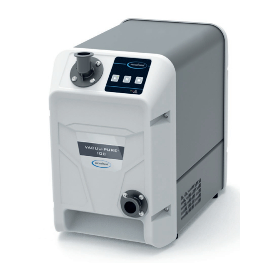
Product description 3.1 VACUU·PURE 10C VACUU·PURE 10C Side and front view Rear view Description Recessed grip on front Inlet – vacuum connection Control panel Outlet – outlet connection Air vents Recessed grip on rear + cooling air outlet Rating plate Mains connection, device fuse, on/off switch VACUU·BUS plug‑in connection / Modbus connection VACUU·BUS socket: Accessories... -
Page 27: Optional Accessories
Product description 3.2 Optional accessories Optional accessories see also chapter: 8.2 Ordering information on page 85 8.2 Ordering information on page 3.2.1 3.2.1 Vacuum pump accessories Vacuum pump accessories Separator, vapor condenser and the VACUU·PURE VACUU·PURE shuttle shuttle are Optional accessories for the available as separate accessories for mounting on the vacuum... - Page 28 Product description Overview of vacuum pump accessories Optional accessories: separator and vapor condenser VACUU·PURE shuttle Separator (AK) at the inlet of the vacuum pump; connection via KF DN 25 (vacuum pump inlet flange rotated) Vapor condenser (EK) at the outlet of the vacuum pump; connection via KF DN 25 VACUU·PURE shuttle VACUU·PURE shuttle ;...
-
Page 29: Vacuu·bus Accessories
Product description 3.2.2 3.2.2 VACUU·BUS accessories VACUU·BUS accessories The lower VACUU·BUS port on the back of the vacuum pump Connect offers a variety of expansion options for connecting VACUU·BUS VACUU·BUS components components. You can use VACUU·BUS extension cables and Y‑adapters to distribute and connect several components. -
Page 30: Modbus Rtu Protocol
Product description 3.2.3 3.2.3 Modbus RTU protocol Modbus RTU protocol The upper VACUU·BUS port on the back of the vacuum pump is intended for remote operation of the vacuum pump, via Modbus RTU protocol, see separate operating manual for description of the Modbus RTU. -
Page 31: Application Example
Product description 3.3 Application example Application example Freeze drying Example: Freeze drying Description Vacuum pump VACUU·PURE 10C VACUU·PURE 10C Inlet line Outlet line (diverted into a fume hood) Example of use: Lab freeze dryer 20901224_EN_VACUU·PURE 10C_V1.8_221122... -
Page 32: Installation And Connection
Installation and connection Installation and connection Installation and connection 4.1 Transport Transport Products from VACUUBRAND are packed in sturdy, recyclable packaging. The original packaging is accurately matched to your product for safe transport. If possible, please keep the original packaging, e.g., for returning the product for repair. -
Page 33: Set Up The Vacuum Pump
Installation and connection > Note that the weight of the vacuum pump is approx. 21 kg. > Carefully lift the vacuum pump out of the packaging using the recessed grips. 4.2 Set up the vacuum pump Set up the vacuum pump NOTE NOTE Condensate can damage the electronics. - Page 34 Installation and connection Set up the vacuum pump Example Sketch of 5 cm minimum distances in lab furniture 5 cm 12 cm > Place the vacuum pump on a stable, non‑vibrating, level surface. > When installing in lab furniture, maintain a minimum IMPORTANT! distance of 5 cm (2 in) to adjacent objects or surfaces.
-
Page 35: Connection
Installation and connection IMPORTANT! > Note the IP protection class. IP protection is only guaranteed if the product is appropriately mounted and connected. > When connecting, observe the information on the rating plate and the chapter 8.1.1 Technical data on page 78 8.1.1 Technical data on page 4.3 Connection Connection... - Page 36 Installation and connection NOTE NOTE Foreign bodies in the inlet line can damage the vacuum pump. Prevent particles and contaminants from being aspirated or > being able to flow back. > Use a sufficiently stable vacuum hose that is designed for IMPORTANT! the required vacuum range.
- Page 37 Installation and connection Rotate the inlet flange The inlet flange can be rotated in 90° increments. Example Rotate inlet flange forward 1. Loosen the 4 screws on the 2. 2. Remove the inlet flange. Check inlet flange: Torx screwdriver the O‑ring for damage and that TX25, paying attention to the it is correctly seated.
- Page 38 Installation and connection Connect the vacuum hose > Remove the blind flange on the inlet flange. Vacuum hose at the inlet > Connect a vacuum hose with small flange KF DN 25 to the inlet flange, ensuring the connection is gas‑tight. >...
-
Page 39: Outlet Connection (Out)
Installation and connection 4.3.2 4.3.2 Outlet connection (OUT) Outlet connection (OUT) Connect the outlet WARNING line to the outlet Risk of bursting due to overpressure inside the outlet line. Inadmissibly high pressure in the outlet line can cause the vacuum pump to burst or damage seals. The outlet line (exhaust gas, gas outlet) must always >... - Page 40 Installation and connection Connect the outlet line Outlet line at the > Remove the blind flange on the outlet flange. outlet > Connect an outlet line with small flange KF DN 25 to the outlet flange ensuring the connection is gas‑tight. >...
- Page 41 Installation and connection Front and side view with mounted vapor condenser Connect the outlet line 1. Connect rubber sealing ring (3) (3), hose nozzle (2) (2), and union nut (1) (1) as shown and screw them onto the outlet connection. 2.
- Page 42 Installation and connection Connect the coolant A vapor condenser (EK) has a connection for coolant. Water or the liquid from a chiller, for example, are suitable coolants. > The inlet pressure of the coolant at the vapor condenser IMPORTANT! must be less than 6 bar (87 psi). >...
-
Page 43: Electrical Connection
Installation and connection 4.3.3 4.3.3 Electrical connection Electrical connection Connect the vacuum pump electrically Example Electrical connection for vacuum pump 1. 1. Plug connector (1) of the power cord into the power connection of the vacuum pump. 2. 2. Plug power plug (2) into the power outlet. 5 Vacuum pump electrically connected. -
Page 44: Commissioning (Operation)
Commissioning (operation) Commissioning (operation) Commissioning (operation) 5.1 Switch on Switch on Switch on the vacuum pump Switch on the vacuum pump > Switch rocker switch (1) on – switch position I. 5 The vacuum pump carries out a function test, all LEDs light up for 2 seconds. - Page 45 Commissioning (operation) Operating elements Operating elements Button Operating elements Start vacuum pump Stop vacuum pump Vacuum pump regeneration mode (vacuum pump starts/ continues running at reduced speed) Display elements Display elements Button LED Description Vacuum pump running Vacuum pump stopped Vacuum pump regeneration mode activated Button LED Description...
-
Page 46: Operation
Commissioning (operation) 5.2.1 5.2.1 Operation Operation Start the vacuum pump IMPORTANT! > Make sure that the outlet is clear and non‑pressurized. Start Press key 5 The vacuum pump starts. A clicking switch noise can be heard briefly. Warm-up (warm-up time) The operating principle of the vacuum pump is based on gap Warm‑up time seals. -
Page 47: Regeneration Mode
Commissioning (operation) > The vacuum pump does not create a vacuum‑tight seal when IMPORTANT! it switches off. > If necessary, install an in‑line solenoid valve or shut‑off valve in the inlet line to isolate your application from the vacuum pump with a vacuum‑tight seal. 5.2.2 5.2.2 Regeneration mode Regeneration mode... -
Page 48: Autostart
Commissioning (operation) Dry the vacuum pump before changing media The vacuum pump can be dried with the aspirated ambient air Dry vacuum pump without having to be separated from the application / equipment. > Use regeneration mode or rinse the vacuum pump with water ... -
Page 49: Advanced Operation
Commissioning (operation) 5.3 Advanced operation Advanced operation In addition to the simple operation of the vacuum pump – start, stop, regeneration – you can carry out other functions by pressing and holding individual keys or by combining them. 5.3.1 5.3.1 Display of software / hardware version Display of software / hardware version Display of software / hardware version... - Page 50 Commissioning (operation) Example Display of software version V1.23 (LED on left, yellow) and hardware version V1.05 (LED on right, red): LEDs Meaning / flashing rate Software version display (1 second) Yellow = V 1.XX Yellow = V X.2X Yellow = V X.X3 Yellow 3 seconds pause, LED changes from yellow to Hardware version display (1 second)
-
Page 51: Restore Factory Settings
Commissioning (operation) 5.3.2 5.3.2 Restore Restore factory settings factory settings When restoring the factory settings, any changes made by the Restore factory settings customer – mainly with accessories optionally connected via VACUU·BUS – will be reset to factory settings. > The software version of the vacuum pump is retained and is not reset. -
Page 52: Remote Operation Via Modbus Rtu
Commissioning (operation) The stop button lights up permanently. The vacuum pump's factory settings are restored. 5.3.3 5.3.3 Remote operation via Modbus RTU Remote operation via Modbus RTU Modbus RTU: The upper VACUU·BUS port on the back of the vacuum pump is Remote operation intended for remote operation of the vacuum pump, via Modbus and parameter... -
Page 53: Connect / Remove Vacuu·bus Accessories
VACUU·BUS address. The connection of two components with identical VACUU·BUS addresses leads to errors in the BUS system. (Reconfiguration of the VACUU·BUS address of a component: see operating manual of a VACUUBRAND VACUUBRAND controller, e.g., VACUU·SELECT). Note the maximum permissible load of 11 W at the VACUU·BUS ƒ... -
Page 54: Vacuu·bus Detection
Commissioning (operation) Maximum permissible cable length in the VACUU·BUS system: ƒ 30 m. An interruption in communication with accessories or the removal ƒ of accessories causes the vacuum pump to stop immediately and an error message to be displayed (flashing rate: 6x), see chapter: 6.3.2 Error –... -
Page 55: Operation With Vacuu·bus Accessories
Commissioning (operation) 5.4.2 5.4.2 Operation with VACUU·BUS accessories Operation with VACUU·BUS accessories Operation with in-line solenoid valve The in‑line solenoid valve automatically opens 10 seconds after Operation with ƒ the start button is pressed. The value of the waiting time can be in‑line solenoid valve set via the Modbus RTU protocol: 0 –... - Page 56 Commissioning (operation) After the delay time has expired, the vacuum pump stops ƒ automatically, and an error is displayed. In case of a false alarm with empty flask, a calibration should be ƒ carried out on the empty flask used: Calibrate level sensor Adjust liquid level sensor...
-
Page 57: Shutdown (Switch Off)
Commissioning (operation) 5.5 Shutdown (switch off) Shutdown (switch off) Take the vacuum pump out of operation Shutdown 1. Stop the process. > Avoid deposits and dry the vacuum pump in regeneration IMPORTANT! mode 5 By letting the vacuum pump run on in regeneration mode, you reduce condensate and media residue in the vacuum pump. -
Page 58: Storage
Commissioning (operation) 4. Switch off rocker switch (1) – switch position 0. 5 Vacuum pump switched off. 5. 5. Disconnect the vacuum pump from the apparatus. 6. 6. Check the vacuum pump for possible damage and contamination. 5.6 Storage Storage Store the vacuum pump Store the vacuum 1. -
Page 59: Error Messages
Error messages Error messages Error messages Errors or warnings are indicated by the colored LEDs on the General error messages warning triangle. Several error messages may be pending at the same time. Errors and warnings can be read out via the flashing rate. -
Page 60: Error Indication
Error messages 6.2 Error indication Error indication Possible flashing Flashing Description rates in the event of an error Temperature in the inadmissible range not assigned Motor current consumption in faulty range or other motor error Fan defective Overvoltage or undervoltage in the intermediate circuit of the frequency converter Error / communication interruption VACUU·BUS accessories... -
Page 61: Troubleshooting
7.1 Information on maintenance work on page and ensure that the product is in good working order. > Send defective products to our Service Department or your local distributor for repair! 1 -> Phone: +49 9342 808-5660, fax: +49 9342 808-5555, service@vacuubrand. 20901224_EN_VACUU·PURE 10C_V1.8_221122... -
Page 62: Error - Cause - Remedy
Error messages 6.3.2 6.3.2 Error – Cause – Remedy Error – Cause – Remedy Error – Cause – Error Error ` Possible cause Personnel 3Remedy Remedy Specialist Warning Ambient temperature Observe the increased. vacuum pump's flashing rate limitation of use. Ensure a supply of cooling air. - Page 63 Error messages Error – Cause – Error Error ` Possible cause Personnel 3Remedy Remedy Specialist Warning Supply voltage for Remove any flashing rate control board in connected critical range. VACUU·BUS accessories if too many or replace if faulty. Operator Warning Message: Check pressure in VACUU·BUS...
- Page 64 Error messages Error – Cause – Error Error ` Possible cause Personnel 3Remedy Remedy Resp. Error Ambient temperature Observe the increased. vacuum pump's specialist flashing rate limitation of use. Ensure a supply of cooling air. Minimum clearances Maintain minimum not observed when clearances to installed in lab adjacent objects or...
- Page 65 Resp. Error Other errors (e.g., Perform or incompatible software repeat the specialist flashing rate version, other software update. frequency converter Information about errors). software update: VACUUBRAND > Support > Software Updates Send in vacuum pump. 20901224_EN_VACUU·PURE 10C_V1.8_221122...
- Page 66 Error messages Error – Cause – Error Error ` Possible cause Personnel 3Remedy Remedy Operator Optional No voltage applied. Apply mains accessories: voltage, switch on vacuum pump. Vacuum sensor does VACUU·BUS plug‑in Check VACUU·BUS not display connection or cables plug‑in connection a measured defective or not and wiring.
- Page 67 Error messages Error – Cause – Error Error ` Possible cause Personnel 3Remedy Remedy Operator No or Leak in inlet line or in Check inlet line minimal apparatus. and equipment for leaks. suction power. Optional separator Check and correctly not correctly fitted install separator.
- Page 68 Error messages Error – Cause – Error Error ` Possible cause Personnel 3Remedy Remedy Operator Loud No outlet line Check outlet line operating connected. and connect it correctly. noises Glass flask on Assemble glass optional EK is flask. missing. Optional EK not Check small flange correctly fitted.
-
Page 69: Cleaning And Maintenance
Cleaning and maintenance Cleaning and maintenance Cleaning and maintenance WARNING Danger due to electrical voltage. Switch the product off before cleaning or > maintenance work. Unplug the power plug from the socket. > Risk from contaminated parts. Pumping hazardous media can result in hazardous substances adhering to internal parts of the pump. -
Page 70: Information On Maintenance Work
Cleaning and maintenance 7.1 Information on maintenance work Information on maintenance work Recommended maintenance activities Maintenance Maintenance intervals If required intervals Clean surfaces Clean / vacuum fan grilles Clean / rinse vacuum pump Replace filter at air inlet for regeneration mode Recommended aids ... -
Page 71: Cleaning
Cleaning and maintenance 7.2 Cleaning Cleaning This chapter does not contain descriptions for decontamination of the product. This chapter describes simple measures for cleaning and care. > Switch off vacuum pump before cleaning. 7.2.1 7.2.1 Clean the vacuum pump Clean the vacuum pump Clean surfaces >... -
Page 72: Empty Glass Flask (Accessories)
Cleaning and maintenance 7.2.2 7.2.2 Empty glass flask (accessories) Empty glass flask (accessories) Remove and empty glass flask at AK and / or EK > Ventilate the glass flask at the inlet of the vacuum pump IMPORTANT! before opening the joint clamp. Empty the glass flask 1. -
Page 73: Rinse Vacuum Pump
Cleaning and maintenance 7.3 Rinse vacuum pump Rinse vacuum pump To rinse the vacuum pump, distilled water is pumped through it while it is running. DANGER DANGER Risk of explosion due to use of solvents. The aspiration of solvents with air can lead to the formation of explosive mixtures. - Page 74 Cleaning and maintenance Rinse vacuum pump > Use a commercially available drip bottle or spray bottle to Rinse vacuum pump rinse the vacuum pump. > Only use distilled water to rinse the vacuum pump. > Run the vacuum pump in regeneration mode. Example of rinsing the vacuum pump 1.
- Page 75 Cleaning and maintenance 3. Gradually spray the distilled water directly into the pump inlet with the drip or spray bottle. 4. 4. Rinse gradually with about 200 ml of distilled water. 5. 5. If necessary, repeat the cleaning process until all residue is rinsed out of the vacuum pump.
-
Page 76: Air Inlet Filter
Cleaning and maintenance 7.4 Air inlet filter Air inlet filter Position of the filter (air inlet for regeneration mode) on the vacuum Replacement of air inlet filter pump: (regeneration mode) > Replace a dirty or clogged air filter at the air inlet for regeneration mode. -
Page 77: Replace The Device Fuse
Cleaning and maintenance 7.5 Replace the device fuse Replace the device fuse You will find 2 device fuses at the power supply connection on Replace the device fuse the back of the vacuum pump, type: 250 V / 8 AT – 5x20 Replace the device fuse 1. -
Page 78: Appendix
Appendix Appendix Appendix 8.1 Technical information Technical information 8.1.1 8.1.1 Technical data Technical data Vacuum pump Vacuum pump Ambient conditions (US) technical data Ambient temperature, max. 10 – 40 °C 50 – 104 °F Storage/transport temperature ‑10 – 60 °C 14 –... - Page 79 Appendix Technical data Electrical data Nominal voltage 100 – 230 V ±10 % Nominal frequency 50 / 60 Hz Overvoltage category Power, max. 700 W Interface VACUU·BUS / Modbus RTU Power cord Max. permissible load on 11 W VACUU·BUS connections Device fuse 2x 250 V / 8 AT –...
- Page 80 Appendix Frequency converter Frequency converter Frequency converter technical data Type FC 700S 10 Ambient conditions (US) Ambient temperature, max (end 10 – 40 °C – 104 °F use) Storage/transport temperature ‑10 – 60 °C 14 – 140 °F Installation height, maximum 2000 m 6562 ft (end use)
- Page 81 Appendix Overview of frequency converter board Inputs and outputs on the frequency converter board Shield circuit board Power supply connection Control cable connection Motor connection Encoder connection 20901224_EN_VACUU·PURE 10C_V1.8_221122...
-
Page 82: Rating Plates
Appendix 8.1.2 8.1.2 Rating plates Rating plates Specifications on > In the event of an error, make a note of the type and serial the rating plate number on the rating plate. > When contacting our Service Department, please provide the type and serial number from the rating plate. -
Page 83: Wetted Materials
Appendix 8.1.3 8.1.3 Wetted materials Wetted materials Wetted materials Component Wetted materials Inlet flange, outlet flange, silencer, end cover of the pump unit Spindles, stator, bearing plate PEEK Gaskets, flat gasket at the outlet Non‑return valve PPS / PTFE / chemically resistant fluoroelastomer Hose between non‑return valve and PTFE... -
Page 84: Use Of Chemicals
Appendix 8.1.4 8.1.4 Use of chemicals Use of chemicals Use of chemicals NOTE NOTE Chemicals can damage the vacuum pump. Chemicals can damage the wetted parts of the vacuum pump. Check the compatibility of the pumped substances with the > wetted materials of the vacuum pump, ... -
Page 85: Ordering Information
Appendix 8.2 Ordering information Ordering information Vacuum pump Vacuum pump Order no. ordering information VACUU·PURE 10C 20751000 20751001 20751002 20751003 20751006 20751007 Ordering information Accessories Order no. for accessories Separator AK 20751802 Vapor condenser EK 20751801 VACUU·PURE shuttle 20751800 Adapter KF DN 25 / SW DN 15, PP 20662808 Adapter KF DN 25 / SW DN 10, PP 20662807... - Page 86 Information about our complete product range is available in the current product catalog. > Your local distributor or VACUUBRAND GMBH + CO KG VACUUBRAND GMBH + CO KG sales office is available to assist you with orders, questions on vacuum control and optimal accessories.
-
Page 87: Service
> Visit our website for further information: www.vacuubrand. com. Service handling Meet > Follow these headings: VACUUBRAND > Support > Service terms of service Reduce downtime, speed up processing. Please have the required data and documents at hand when contacting our Service Department. -
Page 88: Index
Appendix 8.4 Index Index Index Abbreviations ........10 Labels and signs ......22 Accessories ........85 Level sensor ........55 Action steps ........9 Limitation of use ......34 Additional symbols ......8 Adjust liquid level sensor ....56 Maintain minimum distance ..... 22 Advanced operation ...... - Page 89 Appendix Index Shutdown ......... 57 Sources of supply ......86 Spare parts ........85 Start ..........46 Switch on ......... 44 Symbols ..........8 Target groups ........16 Technical data for vacuum pump ..78 Technical information ....... 78 Technical support ......61 Term definitions .......
-
Page 90: Ec Declaration Of Conformity
Hersteller / Manufacturer / Fabricant: VACUUBRAND GMBH + CO KG VACUUBRAND GMBH + CO KG · Alfred-Zippe-Str. 4 · 97877 Wertheim · Germany Hiermit erklärt der Hersteller, dass das Gerät konform ist mit den Bestimmungen der Richtlinien: Hereby the manufacturer declares that the device is in conformity with the directives: Par la présente, le fabricant déclare, que le dispositif est conforme aux directives:... -
Page 91: Ukca Declaration Of Conformity
Conformity Manufacturer: VACUUBRAND GMBH + CO KG VACUUBRAND GMBH + CO KG · Alfred-Zippe-Str. 4 · 97877 Wertheim · Germany Hereby the manufacturer declares that the device is in conformity with the directives: Supply of Machinery (Safety) Regulations 2008 ƒ... -
Page 92: Cu Certificate
Appendix 8.7 CU Certificate CU Certificate CU Certificate 20901224_EN_VACUU·PURE 10C_V1.8_221122... - Page 93 20901224_EN_VACUU·PURE 10C_V1.8_221122...
- Page 94 20901224_EN_VACUU·PURE 10C_V1.8_221122...
- Page 95 20901224_EN_VACUU·PURE 10C_V1.8_221122...
- Page 96 VACUUBRAND > Support > Manuals Manufacturer: VACUUBRAND GMBH + CO KG VACUUBRAND GMBH + CO KG Alfred‑Zippe‑Str. 4 Alfred‑Zippe‑Str. 4 97877 Wertheim 97877 Wertheim GERMANY GERMANY Phone: Head office +49 9342 808‑0 Sales +49 9342 808‑5550 Service +49 9342 808‑5660 Fax: +49 9342 808‑5555...
Need help?
Do you have a question about the VACUU-PURE 10C and is the answer not in the manual?
Questions and answers