
Related Manuals for vacuubrand MD 1


Summary of Contents for vacuubrand MD 1
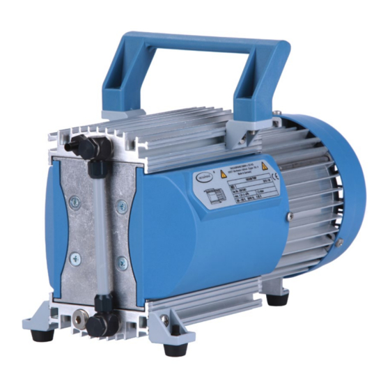
- Page 1 1 of 72 Technology for Vacuum Systems Instructions for use MD 1 VARIO-SP MD 1 Diaphragm pumps...
- Page 2 VACUU•LAN (US-Reg.No 3,704,401), VACUU•BUS , VACUU•CONTROL ® ® ® Peltronic , VARIO (US-Reg.No 3,833,788), VACUUBRAND (US-Reg.No ® ® ® 3,733,388) and also the shown company logos are registered trademarks of VACUUBRAND GMBH + CO KG in Germany and/or other countries.
- Page 3 page 3 of 72 Achtung: Die vorliegende Betriebsanleitung ist nicht in allen EU-Sprachen verfügbar. Der Anwender darf die beschriebenen Geräte nur dann in Betrieb nehmen, wenn er die vorliegende Anleitung versteht oder eine fachlich korrekte Übersetzung der voll- ständigen Anleitung vorliegen hat. Die Betriebsanleitung muss vor Inbetriebnahme der Geräte vollständig gelesen und verstanden werden, und alle geforderten Maß- nahmen müssen eingehalten werden.
- Page 4 page 4 of 72 Bemærk: Denne manual foreligger ikke på alle EU sprog. Brugeren må ikke be- tjene apparatet hvis manualen ikke er forstået. I det tilfælde skal en teknisk korrekt oversættelse af hele manual stilles til rådighed. Manual skal være gennemlæst og forstået før apparatet betjenes og alle nødvendige forholdsregler skal tages.
- Page 5 page 5 of 72 Figyelem! Ez a kezelési utasítás nem áll rendelkezésre az EU összes nyelvén. Ha a felhasználó nem érti jelen használati utasítás szövegét, nem üzemeltetheti a készüléket. Ez esetben a teljes gépkönyv fordításáról gondoskodni kell. Üzembe helyezés előtt a kezelőnek végig kell olvasnia, meg kell értenie azt, továbbá az üzemeltetéshez szükséges összes mérést el kell végeznie.
- Page 6 page 6 of 72 Attentie: Deze gebruiksaanwijzing is niet in alle talen van de EU verkrijgbaar. De gebruiker moet niet met dit apparaat gaan werken als voor hem/haar de gebruiks- aanwijzing niet voldoende duidelijk is. Bij gebruik van deze apparatuur is het nood- zakelijk een technisch correcte vertaling van de complete gebruiksaanwijzing te hebben.
- Page 7 page 7 of 72 Varning: Denna instruktion är inte tillgänglig på alla språk inom EU. Användaren får inte starta utrustningen om hon/han inte förstår denna instruktion. Om så är fallet måste en tekniskt korrekt instruktion göras tillgänglig. Instruktionen måste läsas och förstås helt före utrustningen tas i drift och nödvändiga åtgärder göres.
-
Page 8: Table Of Contents
Abbreviations ..................26 Pump parts ..................26 Replacing the device fuse (only MD 1 C/US) ........30 Replacing the fuse on the circuit board (only MD 1 VARO-SP) ..31 Use and operation ............33 Installation ..................33 Vacuum connection (inlet) ..............33 Connecting the outlet ............... -
Page 9: Safety Information
Make operating personnel aware of dangers arising from the pump and the pumped substances. VACUUBRAND disclaims any liability for inappropri- ate use of these pumps and for damage from failure to follow instructions contained in this manual. - Page 10 page 10 of 72 ➨ DANGER indicates a hazardous situation which, if not avoided, will result in death or serious injury. + WARNING indicates a hazardous situation which, if not avoided, could result in death or serious injury. • CAUTION indicates a hazardous situation which, if not avoided, could result in minor or moderate injury.
-
Page 11: General Information
page 11 of 72 General information Remove all packing material from the packing box. Re- NOTICE move the product from its packing-box and retain all pack- aging until the equipment is inspected and tested. Re- move the protective caps from the inlet and outlet ports and retain for future use. -
Page 12: Setting Up And Installing The Equipment
page 12 of 72 + Comply with all notes on correct vacuum and electri- cal connections; see section „Use and operation“, pg. + Do not use the pump to generate pressure. + The pumps are designed for ambient temperatures during operation between +50°F and +104°F (+10°C and +40°C). - Page 13 page 13 of 72 ➨ Pumps with 24 V DC motor: The pump has no on/off switch. The user has to provide a suitable line discon- nector. The supply cable (pumps with AC motor) may be fitted with a molded European IEC plug or a plug suitable for your local electrical supply.
- Page 14 page 14 of 72 • Connect hoses gas tight at inlet and outlet of the pump. • Ensure that no foreign objects can be drawn into the pump. • Check the power source and the pump’s rating plate to be sure that the power source and the equipment match in voltage, phase, and frequency.
-
Page 15: Ambient Conditions
page 15 of 72 quired actions and adopt suitable safety measures. Ambient conditions ➨ Do not reach for this product if it has fallen into liquid. There is a risk of deadly electrical shock. Unplug the system immediately. + Do not use this product in an area where it can fall or be pulled into water or other liquids. - Page 16 page 16 of 72 are approved for the pumping of potentially explo- sive atmospheres according to their ATEX classifica- tion imprinted on their rating plate, but they are not approved for operation in potentially explosive at- mospheres (see section „ Important information: Equipment marking (ATEX)“, pg.
-
Page 17: Safety During Operation
page 17 of 72 substances, see section „Technical data“, pg. 24. When changing the substances pumped, we recom- mend purging the pump with air or inert gas prior to changing the pumped media. Purging the pump will pump out residues and it will reduce the possibility of reactions of the pumped substances with each other and with the pump’s materials. - Page 18 page 18 of 72 + Comply with applicable regulations when disposing of chemicals. Take into consideration that chemicals may be contaminated. Take adequate precautions to pro- tect people from the effects of dangerous substances (chemicals, thermal decomposition products of fluoro- elastomers).
-
Page 19: Maintenance And Repair
page 19 of 72 Provide appropriate protective measures to allow for the possibility of failure and malfunction. The protective mea- sures must also allow for the requirements of the respec- tive application. Pumps with AC motor: In case of overload, the motor is shut down by a self-hold thermal cutout in the winding. - Page 20 20 of 72 For details and for the online ”Instructions for repair” man- ual see www.vacuubrand.com. In normal use, the lifetime of the diaphragms and valves is typically 15,000 operating hours. Bearings have a typi- cal durability of 40000 h. Motor capacitors have a typi-...
- Page 21 page 21 of 72 + Vent the pump before starting maintenance. Isolate the pump and other components from the vacuum system. Allow sufficient cooling of the pump. Drain condensate, if applicable. Ensure that maintenance is done only by suitably trained NOTICE and supervised technicians.
-
Page 22: Important Information: Equipment Marking (Atex)
The overall category of the equipment depends on the connected com- ponents. If the connected components do not comply with the classifi- cation of the VACUUBRAND equipment, the specified category of the VACUUBRAND equipment is no longer valid. Vacuum pumps and vacuum gauges in category 3 are intended for con- nection to equipment in which during normal operation explosive atmo- spheres caused by gases, vapors or mists normally don’t occur;... - Page 23 page 23 of 72 • The equipment is designated for an ambient and gas inlet temperature during operation of +10 to +40°C. Never exceed these ambient and gas inlet temperatures. If pumping / measuring gases which are not potentially explosive, extended gas inlet temperatures are permissible. See instructions for use, section “Gas inlet temperatures”...
-
Page 24: Technical Data
24 V DC current limitation thermal cutout, (temperature manual reset Motor protection sensor on the MD 1 C/US: addi- circuit board) tional fuse 2.5AT fuse 7 AF Degree of protection IEC 529 IP 42 IP 20 hose nozzle for tubing I.D. 1/4” (6 mm) Inlet G 1/8”... -
Page 25: Wetted Parts
(d) In case of supply voltage below 100V, the lock of the cutout might be restricted. (e) Pumps with voltage changeover switch: IP 40 (f) Measurement according to EN ISO 2151:2004 and EN ISO 3744:1995 at 230V/50Hz respec- tively at 1500rpm (MD 1 VARIO-SP) and ultimate vacuum with silencer at outlet. Wetted parts Components... -
Page 26: Gas Inlet Temperatures
page 26 of 72 Gas inlet temperatures Permitted range of gas Operating condition Inlet pressure temperatures at inlet > 75 Torr (100 mbar) ➨ 50 °F to 104 °F Continuous operation (high gas load) (+10°C to +40°C) < 75 Torr (100 mbar) ➨... - Page 27 27 of 72 MD 1 MD 1 C/US pump with dual-voltage motor...
- Page 28 28 of 72 MD 1 VARIO-SP Ensure sufficient venting of the pump!
- Page 29 page 29 of 72 Only pumps with dual-voltage motor: Voltage selection switch: 1. Disconnect the electrical power cord. 2. Use a screw driver to adjust the voltage selection switch at the terminal box of the pump to the supply voltage: ”115/120”...
-
Page 30: Replacing The Device Fuse (Only Md 1 C/Us)
30 of 72 Replacing the device fuse (only MD 1 C/US) ➨ Switch off the pump. ➨ Disconnect the electrical power cord before un- screwing the fuse holder. Identify and eliminate the cause of failure before switch- ing on the pump again. -
Page 31: Replacing The Fuse On The Circuit Board (Only Md 1 Varo-Sp)
31 of 72 Replacing the fuse on the circuit board (only MD 1 VARO-SP) ➨ Separate the pump from mains. ➨ Wait until live parts are discharged. ➨ Identify and eliminate the cause of failure prior to re- start. - Page 32 page 32 of 72 Remove the defective fuse with a tweezer and replace by a new one of the same type. Layout circuit board Fuse F 7 AF, 125 V, 2 x 7 mm Assemble cover after replac- ing the fuse. Screw cover.
-
Page 33: Use And Operation
page 33 of 72 Use and operation Installation Remove the product from its packing-box. Read the document ”Safety information for Safety information for vacuum equipment vacuum equipment” and observe the in- structions contained therein! Sicherheitshinweise für Vakuumgeräte Safety information for vacuum equipment Avis de sécurité... - Page 34 page 34 of 72 • Reduce the transmission of vibration. Pre- vent mechanical load due to rigid pipelines. Insert elastic hoses or flexible elements as couplings between the pump and rigid pipes. Note: Flexible elements will compress or flatten when evacuated if not designed for use under vacuum.
-
Page 35: Connecting The Outlet
page 35 of 72 When assembling, ensure vacuum-tightness. After as- NOTICE sembly, check the whole system for leaks. Use a suitable valve to isolate the pump from the vacuum application. This is to allow the pump to warm up before pumping condensable vapors and to clean the pump after use before it is switched off. -
Page 36: Electrical Connection
✔ Electrical connection MD 1 (AC motor) Plug in the power cord. • Check the power source and the pump’s O ➨ I rating plate to be sure that the power source and the equipment match in voltage, phase, and frequency. - Page 37 Connect the supply voltage and the control signal to the pump’s control line (see „Control- ling the MD 1 VARIO-SP“, pg. 38). Switch the supply voltage and, if required, the control signal on.
-
Page 38: Controlling The Md 1 Vario-Sp
38 of 72 Controlling the MD 1 VARIO-SP Connecting the cable: The control line contains four differently colored wires. wire in control line assignment +24V DC (supply voltage, max 7A) blue GND (24V) PWM: 5V to max. 24V or voltage input: 0V to 10V DC (max. - Page 39 page 39 of 72 Attention: Electrostatic sensitive device! All work related to the circuit board must be carried out in a ESD protected area or under ESD protective measures! size 2 Slide the cover aside carefully and only as far as necessary.
- Page 40 page 40 of 72 Layout of circuit board terminal board (ST1A / ST1B), connection of control line trimming potentiometer (supply voltage and control signal; see print on the circuit board) Terminal board (Connection of the control line on the circuit board) Voltage supply: Terminal ST1A Supply voltage...
- Page 41 page 41 of 72 External setting of the motor speed via voltage input: Voltage input: analog 0V ..10V DC (max. 24V !) ➨ Connect the black and the white wire ac- cordingly to the terminal board ST1B (see table above). 0V to 10V: Linear increase of the motor speed (0 rpm (at 0V) to 2400 rpm (at 10V))
- Page 42 page 42 of 72 Notes regarding the motor speed Pumping at high motor speed increases the pumping speed of the pump. Ensure sufficient cooling of the pump! Pumping at low motor speed increases the lifetime of diaphragms and valves! The pump attains the best ultimate vacuum in the low speed range be- tween approx.
-
Page 43: During Operation
page 43 of 72 During operation ➨ Vent and dispose of potentially dangerous gases or vapors at the outlet of the pump appropriately. + Due to the high compression ratio, the pump might generate overpressure at the outlet. Check pressure compatibility with system components (e.g., exhaust tubing or exhaust valve) at the outlet. - Page 44 page 44 of 72 Do not start the pump if the pressure difference between NOTICE inlet and outlet ports exceeds max. 16.0 psi (1.1 bar). Attempts to start the pump at higher pressure difference may cause stalling and damage of the motor. Prevent internal condensation, transfer of liq- condensate / dust uids or dust.
-
Page 45: Shutdown & Storage
page 45 of 72 • Note: In case of supply voltage below 100V, the lock of the breaker may not latch and the pump might re- start on its own after sufficient cooling. Take appropri- ate precautions, if an automatic restart of the pump may lead to a dangerous situation. -
Page 46: Accessories
Small flange KF DN 16 / G 1/8” ..............20637425 Hose nozzle DN 6 mm / G 1/8” ..............20637745 Hose nozzle DN 10/6 mm / G 1/8”.............20636062 For additional accessories such as vacuum valves, small-flange components, vac- uum gauges or vacuum controllers, refer to www.vacuubrand.com... -
Page 47: Troubleshooting
page 47 of 72 Troubleshooting Fault Possible cause Remedy ❑ Pump does not ➨ Electrical power cord ✔ Plug in power cord. start or stops im- not plugged in, electri- Check fuse. Check elec- mediately. cal supply failure? trical supply voltage. ➨... - Page 48 page 48 of 72 Fault Possible cause Remedy ❑ Pump too noisy. ➨ Atmospheric or high ✔ Connect hose or silencer pressure at the pump to pump outlet. Be careful inlet? not to cause outlet over- pressure, especially with condensable vapors. ➨...
-
Page 49: Replacing Diaphragms And Valves
➨ Never operate the pump if covers or other parts of the pump are disassembled. ➨ Before starting maintenance, disconnect the electri- cal power cord (MD 1 with AC motor), respectively the control line (MD 1 VARIO-SP). Wait two minutes after isolating the equipment from AC power or from supply voltage to allow the capacitors to discharge. - Page 50 - Regular maintenance will improve the lifetime of the pump and also protect both users and the environment. Service kit for MD 1 ..................20696824 (diaphragms, valves, diaphragm key, silicone rubber tube for silencer) + Service only one side of the pump at a time to avoid the mixing of parts.
- Page 51 page 51 of 72 Tools required (metric): - Diaphragm key width 46 mm - Open end wrench width 15 / 16 mm - 4 mm wide Allen key - Phillips screwdriver size 2...
-
Page 52: Checking Diaphragms And Valves
page 52 of 72 Checking diaphragms and valves Position Component Housing cover Valves Head cover Diaphragm clamping disc with square head screw Diaphragm Diaphragm support disc Washers Connecting rod Housing... - Page 53 page 53 of 72 15 mm size 2...
- Page 54 page 54 of 72 + Clean. 20696264...
-
Page 55: Replacing The Diaphragm
page 55 of 72 Replacing the diaphragm... - Page 56 page 56 of 72 + Pay attention to number of washers!
- Page 57 page 57 of 72 + Pay attention to number of washers!
-
Page 58: Replacing The Valves And Assembling The Pump Heads
page 58 of 72 Replacing the valves and assembling the pump heads... - Page 59 page 59 of 72 + Screw in diagonally at first slightly, then tighten. + 4.4 ft.lbf (6 Nm)
- Page 60 page 60 of 72 + Maintain all pump heads in the same way. 15 / 16 mm size 2...
- Page 61 page 61 of 72 Checking the ultimate vacuum ➨ A fter any intervention at the equipment (e.g., repair / maintenance) the ultimate vacuum of the pump has to be checked. Only if the pump achieves its specified ultimate vacuum, the pump’s leak rate is low enough to ensure that no explosive atmospheres will occur in the inte- rior of the equipment.
-
Page 62: Repair - Maintenance - Return - Calibration
3 or 4. These devices cannot be checked, maintained or re- paired. Also decontaminated devices must not returned to VACUUBRAND due to a residual risk. The same conditions apply to on-site work. No repair, maintenance, return or calibration is possi- ble unless the correctly completed health and safety clearance form is returned. - Page 63 page 63 of 72 If you do not wish a repair on the basis of our quotation, the device may be returned to you disassembled and at your expense. In many cases, the components must be cleaned in the factory prior to repair. For cleaning we use an environmentally friendly water based process.
-
Page 64: Warranty
64 of 72 Warranty VACUUBRAND shall be liable for insuring that this prod- uct, including any agreed installation, has been free of de- fects at the time of the transfer of risk. VACUUBRAND shall not be liable for the consequences... -
Page 65: Health And Safety Clearance Form
* Contact the VACUUBRAND service absolutely before dispatching the device. ** Devices which have been in contact with biological substances of risk level 3 or 4 cannot be checked, main- tained or repaired. Also decontaminated devices must not returned to VACUUBRAND due to a residual risk. ☐... -
Page 66: Ec Declaration Of Conformity Of The Machinery
Bevollmächtigter für die Zusammenstellung der technischen Unterlagen / Person authorised to compile the technical file / Personne autorisée à constituer le dossier technique: Dr. F. Gitmans · VACUUBRAND GMBH + CO KG · Alfred-Zippe-Str. 4 · 97877 Wertheim · Germany Wertheim, 11.04.2019 . - Page 67 Bevollmächtigter für die Zusammenstellung der technischen Unterlagen / Person authorised to compile the technical file / Personne autorisée à constituer le dossier technique: Dr. F. Gitmans · VACUUBRAND GMBH + CO KG · Alfred-Zippe-Str. 4 · 97877 Wertheim · Germany Wertheim, 11.04.2019 .
- Page 68 page 68 of 72 This certificate is only valid for pumps with the respec- tive mark (Licensed Test mark) on the pump rating plate.
- Page 69 page 69 of 72 This certificate is only valid for pumps with the respec- tive mark (Licensed Test mark) on the pump rating plate.
-
Page 70: China Rohs
China RoHS DECLARATION OF CONFORMITY – China RoHS 2 VACUUBRAND GMBH + CO KG has made reasonable efforts to ensure that hazardous mate- rials and substances may not be used in its products. In order to determine the concentration of hazardous substances in all homogeneous materials of the subassemblies, a “Product Conformity Assessment”... - Page 71 (Pb), mercury (Hg), cadmium (Cd), hexavalent chromium (Cr+VI), polybrominated biphenyls (PBB), and polybrominated diphenyl ethers (PBDE). Products manufactured by VACUUBRAND may enter into further devices (e.g., rotary evaporator) or can be used together with other appliances (e.g., usage as booster pumps).
- Page 72 Alfred-Zippe-Str. 4 · 97877 Wertheim / Germany T +49 9342 808-0 · F +49 9342 808-5555 info@vacuubrand.com · www.vacuubrand.com VACUUBRAND GMBH + CO KG - Technology for Vacuum Systems - © 2019 VACUUBRAND GMBH + CO KG Printed in Germany Manual-no.: 20901047 / 04/11/2019...
Need help?
Do you have a question about the MD 1 and is the answer not in the manual?
Questions and answers