Advertisement
Available languages
Available languages
Quick Links
Montage CALEA Online allgemein
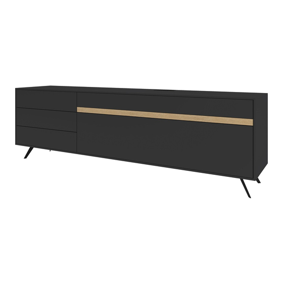
Bild 1 Beispielwände
CE1003
Achtung!
Hängeelemente exakt nach Vorgabe montieren!
Alle kippgefährdete Elemente mit den mitgelieferten
Kippsicherungen befestigen!
Bild 2, Kippsicherungen montieren!
+/-
. Montage CALEA_Online_DE+EN_allg. ab R5952.xlsx 14.03.2022/EFF
Rundkopf-
schraube 4x17
Zylinderkopf-
schraube 5,5x70
CE1016L/R
Niveliergleiter in die
vorgesehenen Bohrungen
eindrücken und Schränke
ausrichten
qualifiziertes
Fachpersonal
CE1002
Bitte beachten!
Bei allen U-Schränken 5-8R, wird ein
Befestigungswinkel mit Metallzapfen als
Kippsicherung montiert. Hierbei wird
Dübel Ø 8mm
eine Senkschraube 5x60mm und ein
Kunststoffdübel Durchm. 8mm
verwendet. Nur bei Schrägmontage
deckt die 13mm Abdeckplatte den
Beschlag ab.
CE1012
CE1013
CE1015
Seite 1/26
Advertisement

Related Manuals for GWINNER CALEA CE1003


Summary of Contents for GWINNER CALEA CE1003
- Page 1 Montage CALEA Online allgemein Bild 1 Beispielwände qualifiziertes Fachpersonal CE1003 CE1002 Achtung! Bitte beachten! Hängeelemente exakt nach Vorgabe montieren! Alle kippgefährdete Elemente mit den mitgelieferten Kippsicherungen befestigen! Bild 2, Kippsicherungen montieren! Rundkopf- schraube 4x17 Bei allen U-Schränken 5-8R, wird ein Befestigungswinkel mit Metallzapfen als Kippsicherung montiert.
- Page 2 Bild 3, Schränke verbinden, Abdeckplatten montieren CE1003 Stauraum für Kabel Trafo usw. Befestigung Abdeckplatten 13mm an markierten Punkten von innen! (Senkschraube 4x 27mm und Abdeck-Kappen in Korpusfarbe) Verbindungsschraube M4x 28 mit Hülsenmutter Bild 4, Gestellteile verbinden+ befestigen Beispiel CE1003, CE1006 ähnlich CE1008, CE1009, CE1015 Verbindung Gestellteile...
- Page 3 Bild 5, Wandpaneel bohren CE1003 3x Dübel 8mm bohren und Wandhaken eindrehen Die mitgelieferten Dübel sind für folgende Untergründe geeignet: Beton, Vollsteine, Lochsteine, Hohlblocksteine. Bei abweichendem Untergrund ist das Befestigungsmaterial entsprechend auszuwählen. Bild 6, Wandpaneel einhängen CE1003 Justierung Wandpaneele Wandpaneel einhängen Neigung Wandpaneel mit Gabelschlüssel SW 8...
- Page 4 Bild 7, Abdeckplatten+ Beleuchtung montieren CE1002 Verbindungsschraube M4x 28 mit Hülsenmutter Befestigung Abdeckplatten 13mm an markierten Hängeschranke Punkten von innen! 1 Raster (Senkschraube 4x 27mm und Abdeck-Kappen in Korpusfarbe) Detail von hinten mit LED Beleuchtung "LEDSET5" bei KD-Wunsch 4-seitig LED-Profile aufkleben, oben+ unten L=2112mm oben+ unten L=1050mm...
- Page 5 Bild 8, Kombi CE1002 bohren Zylinderkopfschraube CE1002 5,5x70 5x Distanzplatte + Dübel 8mm 75x 75x 8mm Bei H1-Schrank mit Beleuchtung Zylinderkopfschraube 5,5x70 + Dübel 8mm + Wandschienen Holzbohrer WP5L/ WP5R Ø8mm Die mitgelieferten Dübel sind für folgende Untergründe geeignet: Beton, Vollsteine, Lochsteine, Hohlblocksteine.
- Page 6 Bild 10, Abdeckplatte unten ausrichten Beispiel CE1011 ähnlich CE1005, CE1007, CE1012, CE1013, CE1018, CE1028, CE1029, CE1030 Niveliergleiter in die vorgesehenen Bohrungen eindrücken und Schränke ausrichten Bild 11 CE1011 Befestigung Abdeckplatten 13mm an markierten Punkten von innen! (Senkschraube 4x 27mm und Abdeck- Kappen in Korpusfarbe) Abdeck-Kappe vernickelt Ø5mm, für nicht verwendete...
- Page 7 Bild 13, Abdeckplatte+ Füße montieren CE1001 Verbindungsschraube M4x 28 mit Hülsenmutter Befestigung Abdeckplatten 13mm an markierten Punkten von innen! (Senkschraube 4x 27mm und Abdeck-Kappen in Korpusfarbe) Niveliergleiter in die vorgesehenen Bohrungen eindrücken und Schränke ausrichten Bild 14, Hängeschränke bohren CE1001 3x Distanzplatte 75x 75x 8mm Bei H1-Schrank...
- Page 8 Bild 15, Abdeckplatten+ Beleuchtung montieren CE1001 Befestigung Abdeckplatten 13mm an markierten Punkten von innen! (Senkschraube 4x 27mm und Abdeck-Kappen in Korpusfarbe) Hängeschrank 1 Raster Detail von hinten mit LED Beleuchtung "LEDSET4" bei KD-Wunsch 4-seitig LED-Profile aufkleben, oben+ unten L=2112mm Profile seitlich L=171mm (Q-Line Mini Opal) Kabelauslass innen!
- Page 9 Bild 16, Schränke einhängen CE1001 Justierung der Hängeschränke Rote Schraube Nr. 3 festziehen, Aushängesicherung! Bohr- /Einbaumaße Wandborde mit Holzboden CE1020L/R CE1021L/R andere Einbauhöhen siehe Auftrags-Servicecard (Grafik) Die mitgelieferten Dübel sind für folgende Untergründe geeignet: Beton, Vollsteine, Lochsteine, Hohlblocksteine. Bei abweichendem Untergrund ist das Befestigungsmaterial entsprechend auszuwählen. Einstellung Frontspalt mit Push Push-Beschlag am Schrank montiert,...
- Page 10 Ausrichten der Türen durch Nachstellen der Scharniere Banddemontage ausrichten der Tür in senkrechter Richtung Ein- bzw. Ausschalter der Tür- Dämpfung! öffnen Tiefenverstellung Bandabdeckung: Bei gekröpften Bändern, gekröpfte Abdeckung verwenden ausrichten der Tür mit der Verstellschraube in waagerechter Richtung Schubkasten Höhen- Feinjustierung Schubkasten Seiten- Feinjustierung...
- Page 11 Schubkasten Neigung verstellen Schubkasten Frontspalt einstellen Schubkasten aushängen Schubkasten einhängen . Montage CALEA_Online_DE+EN_allg. ab R5952.xlsx 14.03.2022/EFF Seite 11/26...
- Page 12 Beleuchtungsplan CE-Online ohne FKS Wichtiger Hinweis zur LED-Beleuchtung: Anschluß der Leuchten nur an Sicherheits- trafos nach EN 61558 (VDE 570), 12 Volt Achtung, max. Belastung vom Trafo Gleichspannung (DC). beachten! Eine Überlastung vom Trafo verkürzt die Betriebsdauer! Defekt!!! EVG-LED, 6 fach-Verteiler, 12V-DC (weißes Stecksysem), 15 Watt, 230V L.
- Page 13 Beleuchtungsplan CE-Online mit FKS4 Wichtiger Hinweis zur LED-Beleuchtung: Achtung, max. Belastung vom Trafo Anschluß der Leuchten nur an Sicherheits- beachten! Eine Überlastung vom Trafo trafos nach EN 61558 (VDE 570), 12 Volt verkürzt die Betriebsdauer! Defekt!!! Gleichspannung (DC). LED-Glaskantenband "LN165"/ "LN120" L.
- Page 14 General CALEA Online assembly instructions Image 1 Example walls Qualified specialist personnel CE1003 CE1002 Caution! Please note! Follow the specifications carefully when fitting wall units. Secure any elements that may tip with the anti-tip mechanisms supplied. Image 2 Fitting the anti-tip mechanism 4x17 fillister- head screw On all 5-8-increment U cabinets, a fixing...
- Page 15 Image 3 Joining cabinets, fitting cover panels CE1003 Storage compartment for cables, transformer, etc. Secure the 13-mm cover panels at the marked points from the inside. (4x27mm countersunk screw and cover caps in the carcase colour) M4x28 connecting screw with sleeve nut Image 4 Joining and securing base elements Example CE1003, CE1006 similar to...
- Page 16 Image 5 Drilling the wall panel CE1003 Drill three 8-mm wall plugs and screw in the wall hook The wall plugs supplied are suitable for the following sub-surfaces: Concrete, solid brick, ventilating brick, hollow concrete blocks. If there is a different subsurface, select an appropriate fixing material. Image 6 Hanging the wall panel CE1003 Adjusting...
- Page 17 Image 7 Fitting cover panels and lighting CE1002 M4x28 connecting screw with sleeve nut Secure the 13-mm cover panels at the marked points from the Wall units inside. 1 increment (4x27mm countersunk screw and cover caps in the carcase colour) Detailed view of rear with LED "LEDSET5"...
- Page 18 Image 8 Drilling the CE1002 combination Cylinder-head screw CE1002 5.5x70 5x distance and 8-mm wall plug spacers 75 x 75 x 8 mm For H1 cabinet with lighting 5.5x70 cylinder-head screw and 8-mm wall plug + wall rails Wood drill WP5L/WP5R Ø8 mm The wall plugs supplied are suitable for the following sub-surfaces: Concrete, solid brick,...
- Page 19 Image 10 Aligning the lower cover panel Example CE1011 similar to CE1005, CE1007, CE1012, CE1013, CE1018, CE1028, CE1029, CE1030 Push the levelling gliders into the intended holes and align the cabinets Image 11 CE1011 Secure the 13-mm cover panels at the marked points from the inside.
- Page 20 Image 13 Fitting the cover panel and feet CE1001 M4x28 connecting screw with sleeve nut Secure the 13-mm cover panels at the marked points from the inside. (4x27mm countersunk screw and cover caps in the carcase colour) Push the levelling gliders into the intended holes and align the cabinets Image 14 Drilling the wall units...
- Page 21 Image 15 Fitting cover panels and lighting CE1001 Secure the 13-mm cover panels at the marked points from the inside. (4x27mm countersunk screw and cover caps in the carcase colour) Wall unit 1 increment Detailed view of rear with LED "LEDSET4"...
- Page 22 Image 16 Hanging the cabinets CE1001 Adjusting the wall units Tighten the red screw no. 3, safety catch. Drilling/installation dimensions for wall shelves with wooden shelves CE1020L/R CE1021L/R For other installation heights, see order service card (graphic) The wall plugs supplied are suitable for the following sub-surfaces: Concrete, solid brick, ventilating brick, hollow concrete blocks.
- Page 23 Align the doors by adjusting the hinges Fitting the hinge Align the door vertically off switch for door soft-close. Open Depth adjustment Hinge cover: Use the offset cover for offset hinges Align the door horizontally using the adjusting screw Drawer-height fine adjustment Drawer side fine adjustment...
- Page 24 Adjust drawer angle Adjust drawer front gap Remove the drawer from its runners Fit the drawer back on its runners . Montage CALEA_Online_DE+EN_allg. ab R5952.xlsx 14.03.2022/EFF Seite 24/26...
- Page 25 Important information about LED lighting: CE Online lighting plan without radio remote control Only connect the lights to the safety transformers in accordance with EN 61558 Caution: Note the maximum transformer (VDE 570) using 12-volt direct current (DC). load. Overloading the transformer reduces its service life.
- Page 26 CE Online lighting plan with FKS4 Important information about LED lighting: Caution: Note the maximum transformer Only connect the lights to the safety load. Overloading the transformer transformers in accordance with EN 61558 reduces its service life. Fault! (VDE 570) using 12-volt direct current (DC). LED glass edge strip "LN165"/ "LN120"...
Need help?
Do you have a question about the CALEA CE1003 and is the answer not in the manual?
Questions and answers