Advertisement
Quick Links
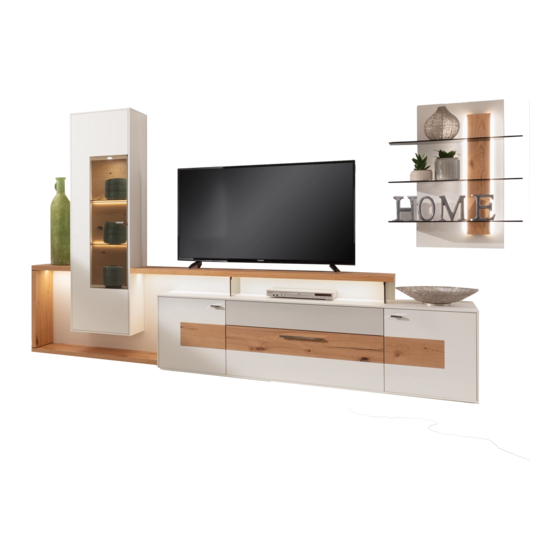
GENERAL INSTALLATION
MEDIA CONCEPT
FROM R6150 ONWARDS
IMAGE 1, Example walls MC969K, HB8-11, SB4-1
PLEASE NOTE!
CAUTION! Follow the specifications carefully when fitting wall units. Secure all
elements that may tip with the anti-tip mechanisms supplied.
IMAGE 2, fitting the anti-tip mechanism
4x17
fillisterhead
screw
5.5x70
cylinderhead screw
Push the levelling gliders
into the intended holes and
align the cupboards
GENERAL MEDIA CONCEPT INSTALLATION
Wall plug,
dia. 8mm
+/-
Qualified specialist personnel
On all 4-increment and 8-increment U
cupboards, a fixing bracket with metal
pins is fitted as an anti-tip mechanism.
A 5x60 mm countersunk screw and an
8-mm-dia. plastic wall plug is used
to do so. The 13-mm cover panel
only covers the fittings on angled
assemblies.
1
Advertisement

Related Manuals for GWINNER MEDIA CONCEPT MC969K


Summary of Contents for GWINNER MEDIA CONCEPT MC969K
- Page 1 GENERAL INSTALLATION MEDIA CONCEPT FROM R6150 ONWARDS Qualified specialist personnel IMAGE 1, Example walls MC969K, HB8-11, SB4-1 PLEASE NOTE! CAUTION! Follow the specifications carefully when fitting wall units. Secure all elements that may tip with the anti-tip mechanisms supplied. IMAGE 2, fitting the anti-tip mechanism On all 4-increment and 8-increment U cupboards, a fixing bracket with metal pins is fitted as an anti-tip mechanism.
- Page 2 IMAGE 3, fitting the cover panels and feet MC969K Secure the 13-mm cover panels at the marked points from the inside. Use 4x27 mm countersunk screws and cover caps Push the levelling gliders into the intended holes and align the cupboards, removing the fronts if necessary IMAGE 4, pre-assembling the rear-panel cover pane Screw the bottom rear panel...
- Page 3 IMAGE 6 Six dia. 8x50 Connect the supporting section panel to the wooden supporting section side panel from below using two Seko Spax 5x 80 screws Adjust the rear panel in the groove Connect the rear panel to the supporting section panel and side panel at a right angle! IMAGE 7 Drill dowels 8mm and...
- Page 4 MC969K Senkschraube 4x 27mm und Abdeck- Kappen 2x Einschraub- IMAGE 8 dübel Rastex Two Rastex obere Justierschraube = screw-in dowels Secure the 13-mm cover Tiefenverstellung panels at the marked points from the inside. untere Justierschraube = Use 4x27 mm countersunk Höhenverstellung screws and cover caps Upper adjustment screw...
- Page 5 Nut für Beleuchtungs- Kabel Bild 9B, Montage LED-Band an obere Spangenplatte 176cm Kabel mit Kabelclip MC969K IMAGE 9B, Fitting the lighting in the upper chipboard 176 cm befestigen+ Nut für Beleuchtungs- Beleuchtungskabel in Kabel Slot for lighting cable Korpus verlegen! MC969K Kabel mit Kabelclip befestigen+...
- Page 6 IMAGE 11, secure the glass shelf to the wall panel Slide the glass shelf into the wall panel SW 5 Securely fix the glass shelf in place and adjust the angle. IMAGE 12, hanging wall panel Adjusting wall panels Hanging wall panels Adjust inclination of wall panel with open-end...
- Page 7 IMAGE 13, adjust push fittings Example with sound cover Removable cable cover with brush seal Push-fittings fitted to the cupboard, adjustable using the magnetic locking system Push the cover to open it. IMAGE 14, drilling the wall units and wall panels Combi MC917 with supporting sections SP67 Drill the 8-mm wall plug and 5.5x70 cylinder-head screw...
- Page 8 IMAGE 15, secure the glass shelf to the wall panel Slide the glass shelf into the wall panel Securely fix the glass shelf in place and adjust the angle. SW 5 IMAGE 16 Upper adjustment screw = depth adjustment Lower adjustment screw Adjusting the = height adjustment wall units –...
- Page 9 IMAGE 17 Secure the 13-mm cover panels at the marked points from the inside. (4x27 mm countersunk screw and cover caps in the carcase colour) Fit nickel-plated cover caps (dia. 5 mm) over the unused connecting holes in the cupboard sides. M4x28 connecting screw with sleeve nut IMAGE 18, fitting and aligning the plinth box...
- Page 10 IMAGE 20, drilling the hanging shelf (shelf height grid) Drilling/installation dimensions for hanging shelves All holes dia. 8, for KU 8-mm wall plug Increment heights (1 incr. = 176 mm) 162.5 162.5 1413 8R= 1454 162.5 162.5 1589 9R= 1630 162.5 41 121.5 41 121.5...
- Page 11 IMAGE 21, Hanging and aligning hanging shelves Upper adjustment screw = depth adjustment Adjusting the wall units Lower adjustment screw and hanging shelves = height adjustment Caution! Check from above that all fittings have been fitted in the rails. Short rail (125 mm) for shelf 5.5x70 cylinder- head screw...
- Page 12 Image 22, assembling the drawer divider Press in the clips Slide in the glass panels The profiles are preassembled in the drawer EK1-98, 4 glass panels 378x70x4 mm I E1-98, 4 glass panels 298x70x4 mm E2-98, 4 glass panels 298x 170x 4mm E2-65, 3 glass panels 298x170x4 mm EK1-49, EK1-65, 3 glass panels 378x70x4 mm E1-65, 3 glass panels 298x70x4 mm...
- Page 13 Handle assembly Handle assembly for doors and drawers Screw in the handle using two M4x25 plate screws. Align the doors by adjusting the hinges On/off switch Aligning the door in a of the door vertical direction Damping! Hinge covers Depth adjustment Hinge covers: Öffnen Short cover caps are used...
- Page 14 MEDIA CONCEPT height grid, wall units Drilling/installation dimensions for wall units 400 / 514 / 732 mm wode Overall height with end panels = 426 / 514 / 758 mm Increment heights (1 incr. = 1 increment = 176 mm) GENERAL MEDIA CONCEPT INSTALLATION...
- Page 15 MEDIA CONCEPT height grid, panel shelves Drilling/installation dimensions for 7-incr. & 9-incr. wall panels, straight & curved Increment heights (1 incr. = 1 increment = 176 mm) 9R= 1584 7R= 1232 2091 9R= 1584 7R= 1232 1915 9R= 1584 7R= 1232 1787 9R= 1584 7R= 1232...
- Page 16 Drilling dimensions angled shelves WI195G, WI146G, WI114G Drill the 8-mm wall plug and screw in the wall hook WI 1950 mm wide WI 1462 mm wide WI 1138 mm wide Installation height see order service card (graphic) Drilling dimension= top edge of wall panel -79mm The wall plugs supplied are suitable for the following sub-surfaces: Concrete, solid brick, ventilating brick, hollow concrete blocks.
- Page 17 MEDIA CONCEPT lighting plan without radio remote control MediaConcept lighting plan without radio remote control Important information about LED lighting: Caution, Note the maximum transformer Important information about LED lighting: Only connect the lights to the safety transformers load. Overloading the transformer reduces Only connect the lights to the safety in accordance with EN 61558 (VDE 570) using its service life.
- Page 18 MEDIA CONCEPT lighting plan with FKS4 MediaConcept lighting plan with FKS4 Important information about LED lighting: Important information about LED lighting: Caution, Note the maximum transformer Only connect the lights to the safety transformers Caution: Note the maximum Only connect the lights to the safety load.
Need help?
Do you have a question about the MEDIA CONCEPT MC969K and is the answer not in the manual?
Questions and answers