Advertisement
Quick Links
GENERAL INSTALLATION & TOS
TREVISO
FROM R5424 ONWARDS
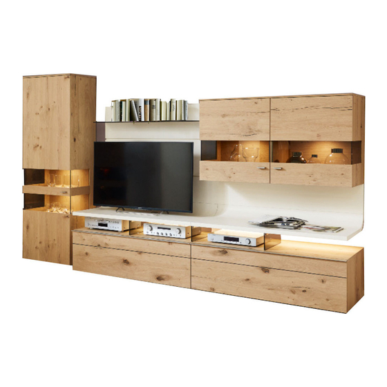
IMAGE 1 Example walls TO203 and TO201
PLEASE NOTE!
CAUTION! Follow the specifications carefully when fitting wall units. Secure all
elements that may tip with the anti-tip mechanisms supplied.
IMAGE 2, Fitting the anti-tip mechanism
4x17 fillisterhead
screw
5.5x70
cylinderhead screw
Push the levelling gliders
into the intended holes
and align the cabinets
GENERAL TREVISO + TOS ASSEMBLY
Wall plug,
dia. 8 mm
+/-
Qualified specialist personnel
On all 5-increment and 8-increment
U cabinets, a fixing bracket with metal
pins is fitted as an anti-tip mechanism.
A 5x60 mm countersunk screw and an
8 mm-dia. plastic wall plug is used to
do so. The 12-mm cover panel only co-
vers the fittings on angled assemblies.
1
Advertisement

Related Manuals for GWINNER TREVISO


Summary of Contents for GWINNER TREVISO
- Page 1 The 12-mm cover panel only co- screw vers the fittings on angled assemblies. Wall plug, dia. 8 mm 5.5x70 cylinderhead screw Push the levelling gliders into the intended holes and align the cabinets GENERAL TREVISO + TOS ASSEMBLY...
- Page 2 5.5x70 cylinder-head screw + 8-mm wall plug The wall plugs supplied are suitable for the following sub-surfaces: Concrete, solid brick, ventilating brick, hollow concrete blocks. If there is a different subsurface, select an appropriate fixing material. GENERAL TREVISO + TOS ASSEMBLY...
- Page 3 5x70 mm pan-head screws (Image 4, central hole = upper carcase edge less 49 mm) IMAGE 6 See Image 2 for information on fitting the anti-tip mechanism See Image 3 for information on fitting the cover panel GENERAL TREVISO + TOS ASSEMBLY...
- Page 4 If there is a different subsurface, select an appropriate fixing material. IMAGE 8, Hanging the wall units Adjusting the wall units – Caution! Check that all fittings have been used. Upper adjustment screw = depth adjustment Lower adjustment screw = height adjustment GENERAL TREVISO + TOS ASSEMBLY...
- Page 5 Always push the cable Fit housings to the lower sleeve in completely. wall panel using M6 stud The sleeve or screw bolts, join the panels and must not protrude. tighten the fittings. GENERAL TREVISO + TOS ASSEMBLY...
- Page 6 Fitting the handle on glass doors with double glass cut-out Fix handle with 3.5x 17 Seko screws Screw in the handle using two M4x25 6 pcs for 130 cm handle, plate screws + two cable sleeves. 9 pcs for 195 cm handle GENERAL TREVISO + TOS ASSEMBLY...
-
Page 7: Depth Adjustment
Only connect the lights to the safety transformers in accordance with EN 61558 (VDE 570) using 12-volt direct current (DC). The total power consumption of the connected lights (see type label) must not exceed the transformer nominal capacity. GENERAL TREVISO + TOS ASSEMBLY... - Page 8 ET1-65, EK1-65, E1-65, 3 glass shelves 476 / 376 / 296 x 70x4 mm Adjusting the front gap using magnets Adjust the front gap by turning the magnets using a screwdriver (On large display-unit doors & base-element flaps) GENERAL TREVISO + TOS ASSEMBLY...
- Page 9 TREVISO height grid, Wall units with base element, 2.3 increments Drilling/installation dimensions for wall units Increment heights (1 incr. = 1 increment = 176 mm) 4R= 704 4R= 704 4R= 704 1643 1643 1775 4R= 704 4R= 704 4R= 704...
- Page 10 TREVISO height grid, wall units with base element, 1.5 increment Drilling/installation dimensions for wall units Increment heights (1 incr. = 1 increment = 176 mm) 4R= 704 4R= 704 4R= 704 1643 1643 1643 4R= 704 4R= 704 4R= 704...
- Page 11 TREVISO lighting plan without radio remote control TREVISO lighting plan without radio remote control Important information about LED lighting: Caution, Note the maximum transformer Important information about LED lighting: Only connect the lights to the safety transformers Caution: Note the maximum transformer load.
- Page 12 TREVISO lighting plan with FKS4 TREVISO lighting plan with FKS4 Important information about the LED Important information about LED lighting: Caution: Note the maximum transformer Caution, Note the maximum transformer lighting: load. Overloading the transformer Only connect the lights to the safety transformers load.
Need help?
Do you have a question about the TREVISO and is the answer not in the manual?
Questions and answers