Advertisement
Quick Links
Advertisement

Related Manuals for POSIFLEX PP-8800U Series


Summary of Contents for POSIFLEX PP-8800U Series
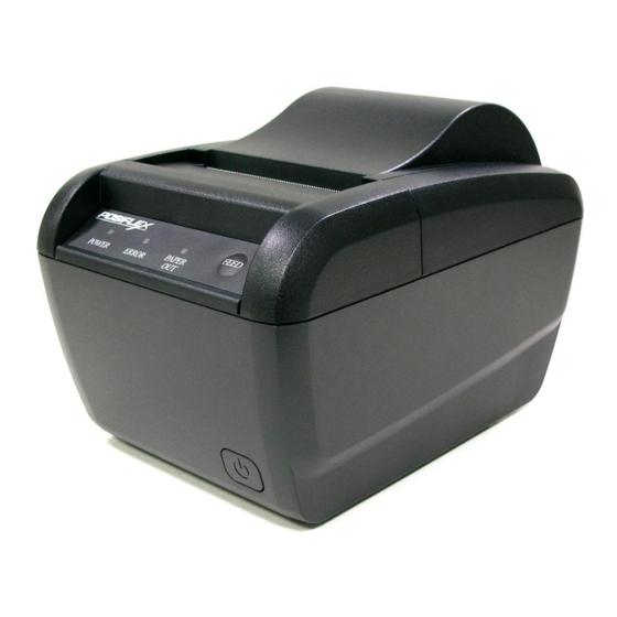
- Page 1 Assembly Disassembly Guide PP-8800U Series...
-
Page 2: Table Of Contents
Assembly Disassembly Guide Table of Contents Maintenance precautions ....................3 Preventive maintenance ....................3 Tools ..........................4 Screws List ........................4 Replacing Control Board ....................5 Replacing 3”Thermal Printer Mechanism ..............9... -
Page 3: Maintenance Precautions
Assembly Disassembly Guide Maintenance precautions -Recommend to use the absolute alcohol for wiping & cleaning. -NOT recommend to use naphtha and strongly corrosive solvents (e.g. with Ammonia, formaldehyde, acetone… included) for cleaning. Preventive maintenance Maintenance items: dust, mildew, water vapor, oil stains, oxidation. -Keep the operation environment with normal humidity &... -
Page 4: Tools
Assembly Disassembly Guide Tools Screwdriver Type Specification Photo Crosshead Point #2 ┿ #2 Screwdriver Crosshead Point #1 ┿ #1 Screwdriver Slotted Thickness ━ Screwdriver 0.4mm Nut setter Hex Across Flat 5.0 Screwdriver Screws List Parts No. Specification Photo 10684038062 BING HEAD SCREW#6/32-6L W/SW+W 10524030102 BING HEAD S-TAP SCREW ∮3-10L 10661030062 PAN HEAD SCREW M3-6L W/SW+PW 10661020052 PAN HEAD SCREW M2-5L W/SW+PW... -
Page 5: Replacing Control Board
Assembly Disassembly Guide Replacing Control Board Loosen the four screws from bottom as indicated in the picture. Screwdriver ┿ #2 Before remove the printer bottom cover, please push the power button, so it’ll be easier to take out the printer bottom cover. Remove the plastic bottom cover as picture shown. - Page 6 Assembly Disassembly Guide Unplug the cables as indicated in the picture. Loosen the three screws as indicated in the picture. Screwdriver ┿ #2 Remove the plastic power button as indicated in the picture. Change a new control board. P/N: 49775604102LN...
- Page 7 Assembly Disassembly Guide Install the new control board, then fasten three screws as indicated in the picture to fix it. P/N:10684038062 Plug the cables as indicated in the picture to the new control board. Prepare the Bottom Plate as picture shown. Place the Bottom Plate on the plastic bottom cover, the shining side facing up, as picture show.
- Page 8 Assembly Disassembly Guide Install the printer bottom cover to the main unit as picture shown. Fasten the four screws as indicated in the picture. P/N: 10524030102 Install the power button as picture shown.
-
Page 9: Replacing 3"Thermal Printer Mechanism
Assembly Disassembly Guide Replacing 3”Thermal Printer Mechanism Loosen the four screws from bottom as indicated in the picture. Screwdriver ┿ #2 Before remove the printer bottom cover, please push the power button, so it’ll be easier to take out the printer bottom cover. - Page 10 Assembly Disassembly Guide Remove the LED cable from the control board as indicated in the picture. Open the paper cover first, then push the cutter cover outward by following the direction as indicated in the picture. Loosen the four screws as indicated in the picture while removing the paper cover.
- Page 11 Assembly Disassembly Guide Unplug the thermal printer cables and the plastic power button as indicated in the picture. Loosen the four screws as indicated in the picture while removing the thermal printer mechanism. Screwdriver ┿ #2 Loosen the three screws as indicated in the picture while removing the cutter cover and ground wire.
- Page 12 Assembly Disassembly Guide Loosen the three screws as indicated in the picture. Screwdriver ┿ #2 Separate the cutter and thermal head as picture shown. Change a new cutter parts. P/N: 39775002000LN Change a new thermal head parts. P/N: 39775003000LN...
- Page 13 Assembly Disassembly Guide On the new cutter parts, separate the parts as picture shown. On the new thermal head parts, press down the blue button as indicated in the picture while releasing the roller. Attach the cutter to the terminal head as indicated in the picture.
- Page 14 Assembly Disassembly Guide Plug the FFC ZIP cable to the thermal printer mechanism as indicated in the picture. (The blue side facing out as picture shown.) Loosen the three screws from the new mechanism first. Then install the cutter cover and the ground wire. Then fasten the three screws back as indicated in the picture.
- Page 15 Assembly Disassembly Guide Fasten the three screws to fix the thermal printer mechanism as indicated in the picture. P/N: 10661030062 Fasten the ground wire on the right side as indicated in the picture. P/N: 10661030062 Plug the thermal printer cables to the control board as indicated in the picture.
- Page 16 Assembly Disassembly Guide Loosen the two screws as indicated in the picture. Then remove the roller from plastic paper cover. Screwdriver ┿ #2 Loosen the two screws as indicated in the picture while removing the roller. Screwdriver ┿ #1 Install the new bracket or roller.
- Page 17 Assembly Disassembly Guide Install the new roller to the plastic paper cover by aligning with the two locating points as indicated in the picture. Fasten the two screws to fix the roller as indicated in the picture. P/N: 10524030102 Turn the terminal printer mechanism to the same direction as picture shown, cutter facing up, while installing it to the plastic paper cover.
- Page 18 Assembly Disassembly Guide Install the plastic cutter cover as picture as picture shown. Plug the LED board cable to the control board as indicated in the picture. Prepare the Bottom Plate as picture shown. Place the Bottom Plate on the plastic bottom cover, the shining side facing up, as picture show.
- Page 19 Assembly Disassembly Guide Install the printer bottom cover to the main unit as picture shown. Fasten four screws as indicated in the picture. P/N: 10524030102 Install the power button as picture shown. Done!
Need help?
Do you have a question about the PP-8800U Series and is the answer not in the manual?
Questions and answers