Table of Contents
Advertisement
Aura Series
PP-8000 / PP-8000L / PP-8000U
THERMAL PRINTER
USER'S MANUAL
FCC Notes:
This equipment generates, uses, and can radiate radio frequency energy and, if not installed and
used in accordance with the instructions manual, may cause interference to radio communications.
It has been tested and found to comply with limits for a Class A digital device pursuant to subpart
J of Part 15 of FCC Rules, which are designed to provide reasonable protection against
interference when operated in a commercial environment. Operation of this equipment in a
residential area is likely to cause interference in which case the user at his own expense will be
required to take whatever measures to correct the interference.
CE manufacturer's Declaration of Conformity
(EC Council Directive 89/336/EEC of 3 May 1989)
This product has been designed and manufactured in accordance with the International Standards
EN50081-1/01.92 and EN50082-1/01.92 following the provisions of the Electro Magnetic
Compatibility Directive of the European Communities as of May 1989
Warranty Limits:
Warranty terminates automatically when any person other than the authorized technicians opens
the machine. The user should consult his/her dealer for the problem happened. Warranty voids if
the user does not follow the instructions in application of this merchandise. The manufacturer is by
no means responsible for any damage or hazard caused by improper application.
About This Manual:
Posiflex has made every effort for the accuracy of the content in this manual. However, Posiflex
will assume no liability for any technical inaccuracies or editorial or other errors or omissions
contained herein, nor for direct, indirect, incidental, consequential or otherwise damages, including
without limitation loss of data or profits, resulting from the furnishing, performance, or use of this
material.
This information is provided "as is" and Posiflex Technologies, Inc. expressly disclaims any
warranties, expressed, implied or statutory, including without limitation implied warranties of
merchantability or fitness for particular purpose, good title and against infringement.
The information in this manual contains only essential hardware concerns for general user and is
subject to change without notice. Posiflex reserves the right to alter product designs, layouts or
drivers without notification. The system integrator shall provide applicative notices and
arrangement for special options utilizing this product. The user may find the most up to date
information
of
the
http://www.posiflex.com.tw or http://www.posiflexusa.com
All data should be backed-up prior to the installation of any drive unit or storage peripheral.
Posiflex will not be responsible for any loss of data resulting from the use, disuse or misuse of this
or any other Posiflex product.
All rights are strictly reserved. No part of this documentation may be reproduced, stored in a
retrieval system, or transmitted in any form or by any means, electronic, mechanical, photocopying,
or otherwise, without prior express written consent from Posiflex Technologies, Inc. the publisher
of this documentation.
© Copyright Posiflex Technologies, Inc. 2009
All brand and product names and trademarks are the property of their respective holders.
P/N: 19770900020
hardware
from
web
Rev.: A0
sites:
http://www.posiflex.com
or
Part 1
Advertisement
Table of Contents

Related Manuals for POSIFLEX AURA PP-8000


Summary of Contents for POSIFLEX AURA PP-8000
- Page 1 Aura Series PP-8000 / PP-8000L / PP-8000U THERMAL PRINTER USER’S MANUAL Rev.: A0 FCC Notes: This equipment generates, uses, and can radiate radio frequency energy and, if not installed and used in accordance with the instructions manual, may cause interference to radio communications. It has been tested and found to comply with limits for a Class A digital device pursuant to subpart J of Part 15 of FCC Rules, which are designed to provide reasonable protection against interference when operated in a commercial environment.
-
Page 2: Getting Started
Posiflex integrated POS system equally perfect. The Aura PP-8000 series support two types of interface input through different sub-codes to the model number. The interfaces are RS232 for serial interface and Centronics for parallel interface. The Aura PP-8000L series connects to a LAN port of Posiflex POS systems. - Page 3 Serial cable with 9 pin D sub Female to 9 pin D sub Male connectors for Aura PP-8000 serial model Parallel cable with 25 pin D sub Male to 25 pin D sub Female connectors for Aura PP-8000 parallel model No interface cable for PP-8000L USB cable for Aura PP-8000U Length of the interface cable depends on whether the order includes the power adaptor.
-
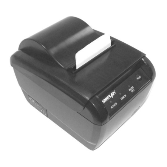
Page 4: Product Pictures
PRODUCT PICTURES Top View Top Hood Paper Exit Top Cover Paper Out LED Hood Release FEED Switch Error LED Power LED Cutter Cover Front View Bottom Cover Power Switch Bottom View Rubber Foot Wall Mount Hanging Hole Window Plate Screw Setup Window Plate Rubber Foot Part 4... - Page 5 Rear View (I/O Area for PP-8000U) USB Adaptor USB Port (I/O Area for PP-8000) Fixation Screw (I/O Area for PP-8000L) Serial Port LAN Port Power Connector Parallel Port Reset Pin Hole for LAN Peripheral Port Frame Ground Screw Spill Protect Cover Paper Exit INDICATORS ...
-
Page 6: Quick Start-Up
QUICK START-UP LOADING PAPER Desk Top Application Release Button Pix. 3 Pix. 1 Pix. 2 Remove the spill protect cover if the option is on. Press down the hood release button to release the top hood as in Pix. 1. Raise the released hood wide open manually as in Pix. - Page 7 in setup window the switch position 1 to OFF, and position 2 to ON leaving the rest unchanged as factory default setting. Parallel Connection The parallel connector is a 25-PIN D sub Male connector at the leftmost location in the connector area for PP-8000. Apply the female end of the parallel cable at this port for parallel application.
- Page 8 (CCBLA-238) is used instead, this port can control two cash drawers of above models. When the printer is used as a kitchen printer, please use this port for kitchen bell connection instead. Power Connection The power connector is a 3-PIN jack between the peripheral connector and the parallel connector for PP-8000.
-
Page 9: Special Adjustments
SPECIAL ADJUSTMENTS Paper Near End Sensor The near end Paper Roll Shaft Hold sensor for paper roll in the printer is able to Sensor Block have the printer work with paper rolls of Sensor Position Adjust several bobbin sizes. Please refer to the picture at right for the Support Roller inside of the paper roll... -
Page 10: Installing Driver
front edge inside the paper exit slot. INSTALLING DRIVER There will always be a Posiflex Product Information CD or DVD or a separate CD of similar nature but specifically created for the product delivered. Please find the appropriate subfolder from the non-specific Posiflex Product Information CD or DVD and check the information file like “readme”... -
Page 11: General Cleaning
OPERATION GUIDE MAINTENANCE GUIDE LINES Always turn off and disconnect power before opening the cover. The areas around the print head and motor become very hot during and just after printing, DO NOT touch them. When handling the interior of the thermal printer, please pay attention not to be hurt by any sharp edge of the metal parts. - Page 12 Printing Problems Nothing can be printed with ERROR LED flashing – Most possible cause for the flashing Error LED is that the printer has been printing for quite a period of time and the print head temperature become too high. After few minutes under normal ventilation, the print head should be able to cool down and the Error LED will stop flashing.
- Page 13 resolve the auto cutter problems per description in next item and then come back to deal with the paper jam. Never force open the top hood. Please also clear away any contaminants accumulated in the cutter track above the thermal elements.
-
Page 14: Useful Tips
when finish. The lock up of the print hood can then be released after this problem solved. Please use manual cutter as temporary alternative measure once the auto cutter malfunctioned. Advanced Analysis Tool This printer supports Hexadecimal Dump for experienced user to view exactly what data is received by the printer. - Page 15 a lot of power or causes great electrical noises, such as a copier, electric motors or a coffee maker. Do not use thermal paper containing Sodium (Na+), Potassium (K+) and Chlorine (Cl-) ions that can harm the print head thermal elements. ...
-
Page 16: Specifications
SPECIFICATIONS PRINTER ITEM SPECIFICATION Printing method Thermal sensitive line dot method Effective printing width 64 mm Thermal head configuration 512 dots / line Printing speed 220 mm / sec. max. Paper feed method Friction auto-feed Paper load method Drop and use Auto-cutter capability Partial cut (1 point at center left) Manual cutter... -
Page 17: Further Technical Information
FURTHER TECHNICAL INFORMATION PRINTER SETUP On bottom cover of the Aura series thermal printer, there is screwed a metal plate for setup window. In this window, there is a 8 position DIP switch for printer setup. Please use proper tool to change the switch setting when necessary. -
Page 18: Advanced Setup
to host only when input buffer is full. When it is set to OFF, busy signal is sent to host whenever the input buffer is full or an off line status occurs. Therefore, signals including the paper near end detect will generate busy signal to the host. Consequently, the printing may be stopped even when there is still a long way to go before the paper roll is actually exhausted. - Page 19 some cases, the printer may have to engage brake frequently waiting for next command resulting in trembling. When this switch is set to OFF, the printer starts printing only when more graphical data from Windows driver are collected thus performing a much smoother printing operation. Switch position 2 is usually set to OFF for use with 80 mm paper width.
- Page 20 Wall Mount Application In wall mount application, the option kit will include screws, plastic cotters and a paper roll shaft. Screws and cotters are to be inserted to holes drilled on wall 80 mm apart center to center horizontally with the non-threaded part of the screw remain above the cotter to hang the printer bottom at holes arrowed in the left picture below.
Need help?
Do you have a question about the AURA PP-8000 and is the answer not in the manual?
Questions and answers