Table of Contents
Advertisement
Quick Links
Advertisement
Table of Contents
Troubleshooting

Related Manuals for Draper 22108


Summary of Contents for Draper 22108
- Page 1 Original Instructions Version 1 12/24V DIESEL TRANSFER PUMP 22108...
-
Page 2: Preface
All photographs and drawings within this manual are document is part of the product; retain it for the life supplied by Draper Tools to help illustrate correct of the product, passing it on to subsequent holders. operation of the product. -
Page 3: Table Of Contents
2. Contents 1. Preface 1.1 Product Reference 1.2 Revisions 1.3 Understanding the Safety Content 1.4 Copyright © Notice 2. Contents 3. Warranty 4. Product Introduction 4.1 Scope 4.2 Specification 4.3 Permitted Liquids 4.4 Performance 5. Health and Safety Information 6. Identification and Unpacking 6.1 Product Overview 6.2 What’s in The Box? 6.3 Packaging... -
Page 4: Warranty
This warranty period covers parts and labour for 12 months from the date of Your Draper Tools guarantee is not effective until you can purchase. Where tools have been hired out, the warranty produce, upon request, a dated receipt or invoice to period covers 90 days from the date of purchase. -
Page 5: Product Introduction
Any other application beyond operate or maintain the product, and retain it for later use. the conditions established for use will be considered misuse. Draper Tools accepts no responsibility for improper use of this product. 4.2 Specification Stock No. -
Page 6: Performance
4. Product Introduction 4.4 Performance The performance of the pump is subject to the distance above the source tank that the pump body is positioned. Input voltage (V) Flow rate (L/min) Absorption (AU) Pressure (bar) Position A (maximum flow rate) Position B (rated conditions) Position C... -
Page 7: Health And Safety Information
Important: DO NOT use this product if it is damaged − ALWAYS ensure that the on/off switch is in the in any way. Contact Draper Tools to discuss repair and “off” position when connecting or disconnecting replacement options. the power supply. -
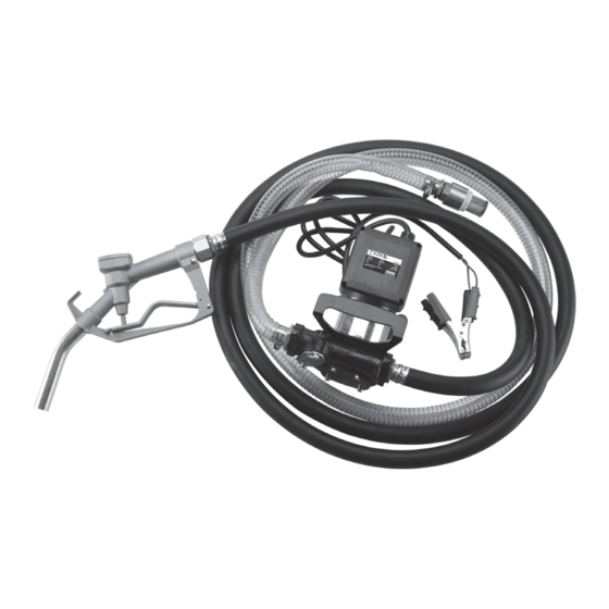
Page 8: Identification And Unpacking
6. Identification and Unpacking 6.1 Product Overview (11) (10) (12) (14) (17) (18) (15) (13) (16) Carry handle Nozzle (15) Pump outlet Fuse access cover On/off switch (16) Rotor access plate Hose clamps (10) Outlet hose (17) Trigger Filter access plate (11) Pickup filter (18) Trigger lock button Inlet hose... -
Page 9: What's In The Box
If any part is occurred during shipment. damaged or missing, do not attempt to use the product. Please contact the Draper Helpline; contact details can be found at the back of this manual. (C2) -
Page 10: Preparation And Assembly
7. Preparation and Assembly Important: Read and understand all the safety instructions listed in this manual before attempting to assemble, operate or maintain this product. ALWAYS ensure that all hose attachments are tightly secured to prevent diesel leakage. 1. Attach the inlet hose (C3) (11) Fig. - Page 11 7. Preparation and Assembly 2. Attach the outlet hose: a. Ensure that each end of the outlet hose (D) is clean and fitted with an O-ring (D2) seal. Fig. 5− b. Attach one end of the outlet hose to the pump outlet (15), marked with OUT around the opening on the pump (Fig.
-
Page 12: Operating Instructions
Squeeze the trigger to the appropriate position Where the pump is positioned below the source tank, and hold it in place (Fig. 6). Draper Tools recommends using an anti-siphon valve For slower speeds, squeeze the trigger (not supplied) on the outlet hose. -
Page 13: Maintenance & Troubleshooting
To clean the internal filter: out by authorised and suitably qualified personnel. Important: ALWAYS drain the pump and hoses into suitable containers before sending the pump to Draper Tools or its agents for repair or replacement. WARNING! ALWAYS ensure that the trigger is released,... -
Page 14: Replacing The Fuse
9. Maintenance and Troubleshooting 9.3 Replacing the Fuse The pump is fitted with a 30A standard blade fuse. To replace the fuse: Fig. 10− 1. Unscrew and remove the fuse access cover (2) (Fig. 10). (20) Fig. 11− 2. Carefully remove the fuse (20) from the holder (Fig. -
Page 15: Troubleshooting
Remove the rotor access plate (16) and examine the rotor. DO NOT use the product if it is damaged. The motor is faulty. Contact Draper Tools to discuss repair and replacement options. The motor turns slowly when There is low voltage across the Check the pump connections to the battery and switched on. -
Page 16: Disposal
10. Disposal At the end of its working life, or when it can no longer be repaired, drain and dispose of the pump according to local regulations. Contact your local authority for details of collection schemes in your area. In all circumstances: • DO NOT dispose of this product with domestic waste. -
Page 17: Explanation Of Symbols
11. Explanation of Symbols UK Conformity Assessed Read the instruction manual Warning! European Conformity WEEE – Waste Electrical & Electronic Equipment Do not incinerate or throw onto fire Do not dispose of Waste Electrical & Electronic Equipment in with domestic rubbish Do not abandon in the environment Wear suitable eye protection Wear protective gloves... - Page 18 Notes – 18 –...
- Page 19 Notes – 19 –...
- Page 20 General Enquiries: +44 (0) 23 8026 6355 General Fax: +44 (0) 23 8026 0784 Service / Warranty Repair Agents For aftersales servicing or warranty repairs, please contact the Draper Tools Product Helpline for details of an agent in your area. © Published by Draper Tools Limited...
Need help?
Do you have a question about the 22108 and is the answer not in the manual?
Questions and answers