Hanna Instruments HI 8510 Instruction Manual
Panel mounted ph and orp indicators and controllers
Hide thumbs
Also See for HI 8510:
- Instruction manual (70 pages) ,
- Instruction manual (68 pages) ,
- Instruction manual (48 pages)

Related Manuals for Hanna Instruments HI 8510


Summary of Contents for Hanna Instruments HI 8510
- Page 1 Instruction Manual HI 8510 • HI 8512 HI 8710 • HI 8711 HI 8720 Panel Mounted pH and ORP Indicators and Controllers w w w. h a n n a i n s t . c o m...
-
Page 2: Table Of Contents
WARRANTY WARRANTY WARRANTY HI 8510, HI 8512, HI 8710, HI 8711 and HI 8720 are guaranteed for two years against defects in workmanship and materials when used for their intended purpose and maintained according to instructions. Electrodes and probes are guaranteed for six months. This warranty is limited to repair or replacement free of charge. -
Page 3: Preliminary Examination
GENERAL DESCRIPTION GENERAL DESCRIPTION GENERAL DESCRIPTION HI 8510 and HI 8512 pH and ORP panel-mounted indicators, and HI 8710, HI 8711 and HI 8720 pH and ORP controllers, are ideal for process control monitoring in a wide range of industrial applications. -
Page 4: Mechanical Dimensions
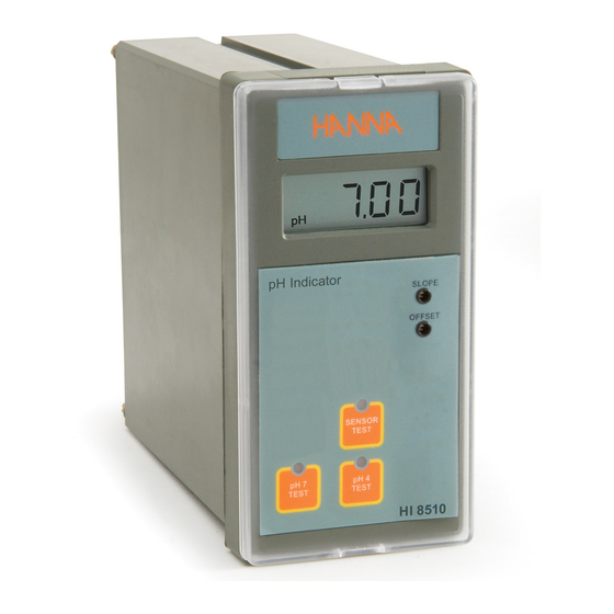
MECHANICAL DIMENSIONS MECHANICAL DIMENSIONS MECHANICAL DIMENSIONS MECHANICAL DIMENSIONS MECHANICAL DIMENSIONS The meters are provided with a black anodized aluminum body, front and back panels in shockproof ABS plastic and a transparent splash-proof front cover. Front view of the panel-mounted unit The dimensions show the cutout size for the installation. -
Page 5: Functional Description Hi 8510
FUNCTIONAL DESCRIPTION HI 8510 FUNCTIONAL DESCRIPTION HI 8510 FUNCTIONAL DESCRIPTION HI 8510 FUNCTIONAL DESCRIPTION HI 8510 FUNCTIONAL DESCRIPTION HI 8510 FRONT PANEL Keypad SENSOR TEST To display the mV reading of the electrode and, therefore, verify its working condition pH 7 TEST... - Page 6 REAR PANEL HI 8510 1. BNC socket for pH electrode 2. Input from amplified electrode 3. Connections for Pt100 temperature sensor 4. Power supply terminals 5. Fuse holder 6. Recorder output terminals 7. Connection to the transmiter 8. Power for amplified electrode 9.
-
Page 7: Functional Description Hi 8512
FUNCTIONAL DESCRIPTION HI 8512 FUNCTIONAL DESCRIPTION HI 8512 FUNCTIONAL DESCRIPTION HI 8512 FUNCTIONAL DESCRIPTION HI 8512 FUNCTIONAL DESCRIPTION HI 8512 FRONT PANEL Keypad 0 mV TEST To verify the instrument calibration at 0 mV 1000 mV TEST To verify the slope at 1000 mV Note: Each time a key is pressed the corresponding LED is turned ON. - Page 8 REAR PANEL HI 8512 1. BNC socket for ORP electrode 2. Input from amplified electrode 3. Power supply terminals 4. Fuse holder 5. Recorder output terminals 6. Connection to the transmitter 7. Power for amplified electrode 8. Connection for matching pin 9.
-
Page 9: Functional Description Hi 8710
FUNCTIONAL DESCRIPTION HI 8710 FUNCTIONAL DESCRIPTION HI 8710 FUNCTIONAL DESCRIPTION HI 8710 FUNCTIONAL DESCRIPTION HI 8710 FUNCTIONAL DESCRIPTION HI 8710 FRONT PANEL Keypad To set the pH dosage limit To enter measurement mode and to enable MEASURE diagnostic tests SENSOR TEST To display electrode mV reading and verify its working condition ΔALARM... - Page 10 SET/COARSE To coarsely adjust the setpoint SET/FINE To finely adjust the setpoint LEDs ACID Shows that acid dosage is active (blinking) ALK. Shows that alkaline dosage is active blinking) ΔALARM Indicates an active alarm (blinking) DOSAGE MODE SWITCH Blinks when the dosing switch is in OFF or ON position.
- Page 11 REAR PANEL HI 8710 1. BNC socket for pH electrode 2. Input from amplified electrode 3. Connections for Pt100 temperature sensor 4. Connections for dosing pump 5. Reduc/Oxid dosage consent terminals 6. Alarm contacts 7. Power supply terminals 8. Fuse holder 9.
-
Page 12: Functional Description Hi 8711
FUNCTIONAL DESCRIPTION HI 8711 FUNCTIONAL DESCRIPTION HI 8711 FUNCTIONAL DESCRIPTION HI 8711 FUNCTIONAL DESCRIPTION HI 8711 FUNCTIONAL DESCRIPTION HI 8711 FRONT PANEL Keypad ALK. SET To set the working point of basic dosage ACID SET To set the working point of acid dosage MEASURE To enter measurement mode and to enable diagnostic tests... - Page 13 Trimmers SLOPE For Slope calibration OFFSET For Offset calibration ΔALARM To set the tolerance of the alarm ALK. SET To coarsely adjust alkaline setpoint COARSE To finely adjust alkaline setpoint FINE ACID SET To coarsely adjust acid setpoint COARSE To finely adjust acid setpoint FINE LEDs ALK.
- Page 14 REAR PANEL HI 8711 1. BNC socket for pH electrode 2. Input from amplified electrode 3. Connections for Pt100 temperature sensor 4. Connections for dosing pump for acid 5. Connections for dosing pump for base 6. Alarm contacts 7. Power supply terminals 8.
-
Page 15: Functional Description Hi 8720
FUNCTIONAL DESCRIPTION HI 8720 FUNCTIONAL DESCRIPTION HI 8720 FUNCTIONAL DESCRIPTION HI 8720 FUNCTIONAL DESCRIPTION HI 8720 FUNCTIONAL DESCRIPTION HI 8720 FRONT PANEL Keypad To set the working point of ORP dosage MEASURE To enter measurement mode and to enable diagnostic tests ΔALARM To display and set the alarm tolerance 0 mV TEST... - Page 16 Trimmers For ORP calibration To display and set the alarm tolerance ΔALARM SET/COARSE To coarsely adjust the setpoint SET/FINE To finely adjust the setpoint LEDs OXID Show that the oxidant dosage is active (Blinking) RED. Show that the reductant dosage is active (Blinking) Indicate an active alarm ΔALARM...
- Page 17 REAR PANEL HI 8720 1. BNC socket for ORP electrode 2. Input from amplified electrode 3. Oxid/Reduc dosage consent terminals 4. Connections for dosing pump 5. Alarm contacts 6. Power supply terminals 7. Fuse holder 8. OXID/RED. dosage selection terminals 9.
-
Page 18: Specifications
SPECIFICATIONS SPECIFICATIONS SPECIFICATIONS SPECIFICATIONS SPECIFICATIONS HI 8510 c e l o r t s n a t i m r e t 0 0 . 0 0 . 1 0 . ± 0 . 0 ) C ° ± C °... - Page 19 HI 8710 c e l o r t r e t 0 0 . 0 0 . 1 0 . ± 2 0 . ) C ° ± 5 . 0 C ° 8 6 / ) C ° ± 5 0 .
- Page 20 N I S A / F O T U N O / s h t c e l e n o i t h c t i I S O u j d b a t s f , e l m o r n i m n i m...
-
Page 21: Initial Preparation
INITIAL PREPARATION INITIAL PREPARATION INITIAL PREPARATION INITIAL PREPARATION INITIAL PREPARATION • • • • • Connect a 3-wire cable to the power supply terminal according to the voltage level as indicated, and pay particular attention to the correct line, earth and neutral connections. •... - Page 22 Connect the “+” wire of the recorder to the terminal 1 on the instrument and the other wire (common) to terminal 2 for 4-20 mA recorder output or to terminal 3 for 0-20 mA recorder output. Note: Only one recorder output connection is possible. In order to avoid malfunction leave the unused terminal unconnected.
- Page 23 • • • • • ALK. contact (HI 8711) (see picture, terminals 3 and 4): these contacts are used to connect the dosing pump for base, and act as a switch for the power to the drive. • • • • • CONSENT contacts (HI 8710 and HI 8720, see picture, terminals 3 and 4): these contacts (max.
-
Page 24: Operational Guide
OPERATIONAL GUIDE OPERATIONAL GUIDE OPERATIONAL GUIDE OPERATIONAL GUIDE OPERATIONAL GUIDE All instrument settings are made via front panel keys and trimmers. When a key is pressed, the corresponding LED lights up to show the operating function. If the LED blinks before pressing the key, it will change the blinking style. - Page 25 Using a small screwdriver adjust the COARSE and FINE trimmers to display the desired set value. SET POINTS (HI 8711) To set the working point for alkaline dosage, press the ALK. SET key and the display will show the set value for alkaline dosage. The ALK. SET LED will turn ON if alkaline dosage is deactivated or change blinking style.
- Page 26 Note: The ALK. and the ACID setpoints can be set on the entire range 0.00 pH to 14.00 pH using COARSE and FINE trimmers. In order to avoid erroneous situations the ALK. setpoint value should not exceed the ACID setpoint value. ALARMS (HI 8710, HI 8711 and HI 8720) To set the alarm tolerance, press ΔALARM key and the display will show the current value.
- Page 27 The actual pH or ORP value of the test solution is displayed. When acid dosage is active, the ACID LED lights up, while during alkaline dosage, the ALK. LED turns on (HI 8710 only). When oxidant dosage is active, the OXID LED lights up, while during reductant dosage, the RED.
-
Page 28: Ph Calibration
Two DOSAGE MODE switches are designed for HI8711, one for ACID and the other for ALK. channels. If for any reason one of them is in OFF position the corresponding dosing relay is deactivated. The alarm relay will be activated only in accordance with the other channel. The ALARM LED will work as in AUTO mode. - Page 29 Rinse pH electrode and the reference thermometer thoroughly with pH 4.01 rinsing solution, then immerse them in pH 4.01 (HI 7004) or pH 10.01 (HI 7010) buffer solution. Note: For accurate readings, use pH 4.01 if you are going to measure acid samples or pH 10.01 for alkaline measurements.
-
Page 30: Ph Values At Various Temperature
p p p p p H VALUES AT VARIOUS TEMPERATURE H VALUES AT VARIOUS TEMPERATURE H VALUES AT VARIOUS TEMPERATURE H VALUES AT VARIOUS TEMPERATURE H VALUES AT VARIOUS TEMPERATURE Temperature has an effect on the pH. The calibration buffer solutions are affected by temperature changes to a lesser degree than normal solutions. -
Page 31: Ph Diagnostic Tests
H DIAGNOSTIC TESTS H DIAGNOSTIC TESTS H DIAGNOSTIC TESTS HI 8510, HI 8710 and HI 8711 are provided with autodiagnostic functions that allow to check and troubleshoot any malfunctioning. The functions are made via front panel keys to isolate the cause of malfunction whether it is due to pH electrode contamination, internal offset circuit or amplifier circuit. - Page 32 C) Amplifier Circuit Test Press the pH 4 TEST key and the display should show a value within the 3.30 to 4.30 pH range, to verify the amplifier circuit of the meter. The corresponding LED turns on.
-
Page 33: Orp Diagnostic Tests
ORP DIAGNOSTIC TESTS ORP DIAGNOSTIC TESTS ORP DIAGNOSTIC TESTS ORP DIAGNOSTIC TESTS ORP DIAGNOSTIC TESTS HI 8512 and HI 8720 are ORP controllers provided with autodiagnostic functions that allow to check and troubleshoot any malfunctioning. The functions are made via front panel keys to isolate the cause of malfunction. -
Page 34: Led Indication
LED INDICATION LED INDICATION LED INDICATION LED INDICATION LED INDICATION All LEDs above the keys indicate the state of each function, whether it is active or the display is indicating the mode. For HI 8711 only Each LED can be in one of the following states: A) Light on The mode is displayed on the LCD but is not active, e.g. -
Page 35: Taking Redox Measurements
TAKING REDOX MEASUREMENTS TAKING REDOX MEASUREMENTS TAKING REDOX MEASUREMENTS TAKING REDOX MEASUREMENTS TAKING REDOX MEASUREMENTS Redox measurements allow the quantification of the solution oxidizing/ reducing power, and are commonly expressed in mV. Oxidation may be defined as the process during which a molecule (or an ion) loses electrons and reduction as the process by which electrons are gained. - Page 36 Oxidizing pre-treatment: immerse the electrode for some minutes in HI 7092 solution. If no pre-treatment is performed, the electrode will have long response times. If working with refillable electrodes, always check the internal electrolyte level and refillwith HI 7071 solution, if necessary (the level must be at least 2.5 cm below the filling hole).
-
Page 37: Electrode Maintenance
ELECTRODE MAINTENENCE ELECTRODE MAINTENENCE ELECTRODE MAINTENENCE ELECTRODE MAINTENENCE ELECTRODE MAINTENENCE PREPARATION PROCEDURE Remove the protective cap. DO NOT BE ALARMED IF ANY SALT DEPOSITS ARE PRESENT. This is normal with electrodes and they will disappear when rinsed with water. During transport tiny air bubbles may form inside the glass bulb, and the electrode cannot function properly under these conditions. - Page 38 Refill the electrode with fresh electrolyte solution (HI 7071 for single junction electrodes or HI 7082 for double junction). Allow the elec- trode to stand upright for 1 hour. Follow the above "Storage Procedure". AmpHel ® is a registered Trademark of "Hanna Instruments"...
- Page 39 CLEANING PROCEDURE • General Soak in HI 7061 general cleaning solution for approximately 1 hour. Removal of films, dirt or deposits on the membrane/junction: • Protein Soak in Hanna HI 7073 protein cleaning solution for 15 minutes. • Inorganic Soak in Hanna HI 7074 inorganic cleaning solution for 15 minutes.
-
Page 40: Suggested Installations
® signal, drastically reducing susceptibility to noise and drift. The sealed electrode body can stand a moisture up to 100% RH without any effect on the signal. AmpHel ® is a registered Trademark of "Hanna Instruments"... - Page 41 If the needed installation distance is greater than 50 m (165'), it is necessary the use of a transmitter. HANNA instruments offers a full line of pH and ORP transmitters with or ® without display. AmpHel ® is a registered Trademark of "Hanna Instruments"...
-
Page 42: Accessories
ACCESSORIES ACCESSORIES ACCESSORIES ACCESSORIES ACCESSORIES pH CALIBRATION SOLUTIONS HI 7004M pH 4.01 buffer solution, 230 mL HI 7004L pH 4.01 buffer solution, 500 mL HI 7006M pH 6.86 buffer solution, 230 mL HI 7006L pH 6.86 buffer solution, 500 mL HI 7007M pH 7.01 buffer solution, 230 mL HI 7007L... - Page 43 pH ELECTRODES HI 1090T Screwcap PG13.5 connector, double junction, glass body HI 1110S Screw connector, single junction, glass body HI 1130B/3 BNC connector, 3 m (9.9') cable, single junction, glass body HI 1110T Screwcap PG13.5 connector, double junction, glass body HI 1114S Screw connector, double junction, plastic body HI 1134B/3...
- Page 44 HI 1210T Screwcap PG13.5 connector, double junction, plas- tic body HI 1910B BNC connector, 1 m (3.3') cable, double junction, plastic body, built-in amplifier HI 1911B BNC connector, 1 m (3.3') cable, double junction, plastic body, built-in amplifier HI 1912B BNC connector, 1 m (3.3') cable, double junction, plastic body, built-in amplifier HI 1912B/5...
- Page 45 ORP ELECTRODES HI 2930B/5 BNC connector, 5 m (16.5') cable, Pt, plastic body, built-in amplifier HI 3110S Screw connector, Pt, glass body HI 3130B/3 BNC connector, 3 m (9.9') cable, Pt, glass body HI 3110T Screwcap PG13.5 connector, Pt, glass body HI 3115S Screw-type connector, side-arm, Pt, glass body HI 3135B/3...
- Page 46 HI 3932B/5 BNC connector, 5 m (16.5') cable, Pt, plastic body, built-in amplifier HI 4110S Screw connector, Au, glass body HI 4130B/3 BNC connector, 3 m (9.9') cable, Au, glass body BNC connector, 5 m (16.5') cable, Au, plastic body, HI 4932B/5 built-in amplifier OTHER ACCESSORIES...
- Page 47 24 VAC or 60 VDC. To avoid damage or burns, do not perform any measurement in microwave ovens. HANNA instruments reserves the right to modify the design, construction and appearance of its products without advance notice.
- Page 48 Hanna Instruments Inc. Highland Industrial Park 584 Park East Drive Woonsocket, RI 02895 USA Local Sales and Customer Service office Hanna Instruments United States Inc. Highland Industrial Park 584 Park East Drive Woonsocket, RI 02895 USA Tel. (800) 426 6287 Fax (401) 765 7575 www.hannainst.com/usa...
Need help?
Do you have a question about the HI 8510 and is the answer not in the manual?
Questions and answers