Table of Contents
Advertisement
Quick Links
Advertisement
Table of Contents

Related Manuals for Hanna Instruments IRIS HI801


Summary of Contents for Hanna Instruments IRIS HI801
- Page 1 HI801 VISIBLE SPECTROPHOTOMETER...
- Page 2 Hanna Instruments representative near you at www.hannainst.com. All rights are reserved. Reproduction in whole or in part is prohibited without the written consent of the copyright owner, Hanna Instruments Inc., Woonsocket, Rhode Island, 02895, USA.
-
Page 3: Table Of Contents
1. PRELIMINARY EXAMINATION ............................. 2. SAFETY MEASURES ................................3. SPECIFICATIONS ................................4. DESCRIPTION ................................... 4.1. GENERAL DESCRIPTION .............................. 4.2. FUNCTIONAL DESCRIPTION ............................4.3. PRINCIPLE OF OPERATION ............................4.4. OPTICAL SYSTEM ................................ 5. OPERATING MODE ................................5.1. START UP ................................... 5.2. - Page 4 6.4.5. DILUTION FACTOR .............................. 6.4.6. VIAL TYPE ................................. 6.4.7. NUMBER OF TIMERS ............................6.4.8. TIMER SETTING ..............................6.4.9. MULTI WAVELENGTH FORMULA .......................... 6.4.10. CALIBRATION ..............................7. METHODS ..................................7.1. FACTORY METHODS ..............................7.2. USER METHODS ............................... 7.3. FAVORITE METHODS ..............................7.4.
-
Page 5: Preliminary Examination
1. PRELIMINARY EXAMINATION Remove the instrument and accessories from the packaging and examine them carefully to make sure that no damage has occurred during shipping. Notify your nearest Hanna Customer Service Center if damage is observed. Each HI801 iris spectrophotometer is supplied with: •... -
Page 6: Specifications
3. SPECIFICATIONS Wavelength Range 340-900 nm Wavelength Resolution 1 nm Wavelength Accuracy ±1.5 nm Photometric Range 0.000-3.000 Abs 5 mAbs at 0.000-0.500 Abs Photometric Accuracy 1% at 0.500-3.000 Abs transmittance (%) Measurement Mode absorbance concentration 10 mm square 50 mm rectangular Sample Cell 16 mm round 22 mm round... -
Page 7: Description
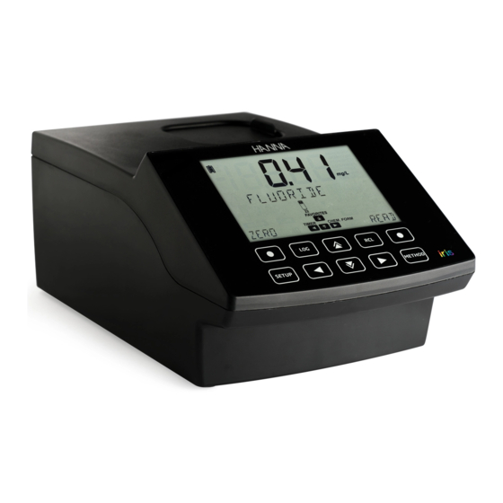
4. DESCRIPTION 4.1.GENERAL DESCRIPTION HI801 iris visible spectrophotometer is a compact and versatile instrument with a split beam optical system. It features a visible wavelength range from 340 to 900 nm. The meter features an internal reference system, that reduces errors caused by lamp intensity and temperature fluctuations. - Page 8 KEYPAD DESCRIPTION The keypad contains 8 direct keys and 2 functional keys with the following functions: Functional keys. Press to perform the function displayed above it on the LCD. Press to access the METHOD menu. Press to move up in a menu to increment a value or to access the FAVORITE METHODS from the MAIN SCREEN. Press to go back to a previous level of the menu, scroll through letter places in the method creation process or to access the TIMER MENU on the MAIN SCREEN.
- Page 9 LCD DESCRIPTION Description Battery Indicator and Charging Status Warning Indicator Timer Indicator Wavelength Indicator Tags used to indicate the selected wavelength or timer Vial type indicator for the selected method* Lamp Status Indicates the Active Menu Indicates Navigation Level in Menus Indicates Arrow Key is Active Calibration Indicator Auto Logging Enabled...
-
Page 10: Principle Of Operation
4.3. PRINCIPLE OF OPERATION Absorption of light is a typical phenomenon of interaction between electromagnetic radiation and matter. A spectrophotometer separates electromagnetic radiation (white light) into its component wavelengths and selectively measures the intensity of the radiation after it passes through a sample. The white light is passed through a prism to disperse the light into bands of color. -
Page 11: Optical System
4.4. OPTICAL SYSTEM Optical System Block Diagram A tungsten halogen lamp is used as the light source for the entire working range of the meter (340 nm to 900 nm). The tungsten halogen lamp produces a white light that is passed to a diffraction grating. The diffraction grating splits the polychromatic white light into the visible color spectrum, allowing for specific wavelengths to be selected. -
Page 12: Operating Mode
5. OPERATING MODE 5.1. START UP When the instrument is powered on, all the LCD tags will be visible for several seconds before the auto-diagnostic tests run. This process will take several seconds, during this time the progress will be displayed on the screen. Once these tests are completed the main screen will be displayed. -
Page 13: Cuvette Adapters
Battery fully charged (connected to power adapter) Battery near 0% (no external power adapter) 5.3. CUVETTE ADAPTERS The HI801 iris spectrophotometer is designed to work with five different cuvettes: • 22 mm round • 16 mm round • 13 mm vial •... - Page 14 5. The meter is ready for use. Always utilize the selected adapter for both "Zero" and "Read" measurements as specified in the method instructions. WARNING: Improper use of the vial adapters could cause irreversible damage to the meter. Always use the flowing precautions when using vial adapters.
-
Page 15: Methods
Factory methods were developed by Hanna Instruments. These methods are pre-programmed with all of the information needed to run an analysis. These methods are calibrated for the selected wavelength, vial type and reagent set, see page 37 for more information. -
Page 16: Data Management
5.6. DATA MANAGEMENT The meter can hold up to 9999 measurements. Data can be reviewed on the screen or transferred to a PC. LOG DATA Data can be saved in two different ways: If Automatic Log is enabled the meter automatically saves the reading. The is shown on the display when this feature is enabled, see page 17 for more information. -
Page 17: Meter Setup
To view the options in the selected submenu press the To return to the main screen press the key. 6.1. METER SETUP Use the key to select METER SETUP, press the key to enter the menu. METER SETUP allows you to modify the meter's general functionality, these settings do not affect the measurement. 6.1.1. -
Page 18: Sample Id
6.1.4. SAMPLE ID Option: ON or OFF If this option is ON the user will be prompted to enter a sample ID when a measurement is saved. 6.1.5. BEEPER Use the key to access the beeper submenu. The available options are: KEY PRESS, ERRORS and TIMERS. KEY PRESS Option: ON or OFF If this option is ON, a short beep is heard every time an active key is touched, a... -
Page 19: Letter Scroll
6.1.7. LETTER SCROLL Option: LETTER SCROLL or WORD SCROLL Press the EDIT key to change the scrolling text. Use the key to select the desired type. Press the CFM key to save the type or the CLR key to return to the setup menu without saving. 6.1.8. - Page 20 DATE FORMAT Option: DD/MM/YYYY, MM/DD/YYYY or YYYY/MM/DD Press the EDIT key to change the date format. Press the key to select the desired date format. Press the CFM key to confirm the date or the CLR key to return to the previous screen without saving.
-
Page 21: Cuvette Detection
6.1.10. CUVETTE DETECTION Option: On or OFF If this option is ON, automatic cuvette detection is enabled. If the wrong cuvette is used an error message will be displayed. If this option is OFF, the indicated cuvette must be used with the factory methods to get a valid measurement. -
Page 22: System Info
6.2.1. SYSTEM INFO This option displays the instrument's serial number, firmware version and baseboard version. Use the key to access the system info menu. Use the key to scroll the displayed information. Use the key to return to the system check menu. 6.2.2. -
Page 23: Lamp History
6.2.5. LAMP HISTORY Press the key to view the number of hours the lamp has been running. Press the RESET key to restart the counter. This should be performed after replacing the lamp. Use the key to return to the system check menu. 6.3. -
Page 24: Reports
USER METHODS Option: Import All or Export All This option allows users to import or export all user methods to/from a USB flash drive. Press the key. Import All will be displayed. Use the key to select the desired option. Insert a USB flash drive and press the CFM key. The process will start automatically, the display will show the progress. - Page 25 BY SAMPLE ID (if enabled) This option allows users to generate and export reports by sample ID. Press the key. The select Sample ID screen is shown. Press the EDIT key to edit the sample ID. Use the key to highlight the digit to be modified.
- Page 26 Press the key to select the file type. The selected file type will be displayed on the screen. Press the EDIT key to change the file type. Use the to select the file type. Press the CFM key to confirm the file type or the CLR key to return to the previous screen without saving.
-
Page 27: Connect To Pc
Press the key to select the file type. The selected file type will be displayed on the screen. Press the EDIT key to change the file type. Use the to select the file type. Press the CFM key to confirm the file type or the CLR key to return to the previous screen without saving. -
Page 28: Method Settings (User Methods Only)
6.4. METHOD SETTINGS (USER METHODS ONLY) Method Settings allows you to modify the settings and calibration curve for to the selected user method. These settings affect the measurement. 6.4.1. MEASUREMENT UNIT Option: None, %T, ABS, ppm, mg/L, ppt, °f, °e, ppb, meq/L, µg/L, PCU, Pfund, pH, mV, dKH, °dH or meq/kg This option allows you to select the measurement unit. -
Page 29: Dilution Factor
6.4.5. DILUTION FACTOR Option: 001 to 100 This option allows the user to set the dilution factor used in sample preparation. This allows samples with high concentrations that are outside the measurement range to be measured. If the sample is not diluted enter a factor of 001. Press the EDIT key to modify the dilution factor. -
Page 30: Timer Setting
6.4.8. TIMER SETTING Option: 00:00 to 59:59 This options allows you to select the timer length. Press the EDIT key to modify the time. Use the key to highlight the digit to be modified. Press the key to set the desired value. U n t i t l e d 1 Press the CFM key to confirm the time or the CLR key to return to the method settings menu without saving. - Page 31 FACTORS The meter will only display and use the factor needed for the selected equation. Use the to select the factor. Press the EDIT key to modify the value. Use the key to highlight the digit to be modified. Press the keys to set the desired value.
-
Page 32: Calibration
6.4.10. CALIBRATION Option: Measure Standards or Manual ABS Entry This option allows users to calibrate user methods by measuring the absorbance of known standards or manually entering absorbance values. Calibrations can contain up to 10 points. Note: This option is only available if a concentration unit is selected (i.e. mg/L, meq/kg, etc.). A calibration cannot be entered for methods using absorbance or % transmittance or multiwavelength methods. - Page 33 Press NO to return to the last calibration point screen or press YES to exit calibration. Press the CFM key to continue. Insert the zero cuvette and press the ZERO key. Insert the first standard and press the READ key. Press the CFM key to save the value and continue or the REDO key to repeat the measurement.
- Page 34 This procedure can be repeated until 10 calibration points have been added. Edit concentration point Measure Abs point MANUAL ABS ENTRY This allows users to enter the absorbance of standards with a known concentration. Up to 10 points can be used to calibrate the method.
- Page 35 Press the EDIT key to modify the absorbance for the first standard. Use the key to highlight the digit to be modified. Press the keys to set the desired value. Press CFM to confirm the value or CLR to return to the method settings menu without saving. To set a negative abs value highlight the first digit and use to select designed value.
- Page 36 VIEW CALIBRATION After a calibration has been completed the calibration data can be viewed using View Calibration. A linear regression is done by the instrument for the saved calibration points, the meter will apply the best straight-line fit to the calibration points. The available options are: SLOPE, OFFSET, R-SQUARED, and CALIBRATION POINTS.
-
Page 37: Methods
7. METHODS Option: FACTORY METHODS, USER METHODS, FAVORITE METHODS (if enabled) and CREATE NEW In order to run an analysis a method needs to be loaded. Use the key to scroll through the available options. The number of methods will be displayed on the lower left side of the screen. Press the key to return to the main screen. -
Page 38: User Methods
7.2. USER METHODS Up to 100 user methods can be stored on the instrument. Use the key to scroll through the methods. To view the methods by ID press the VIEW key. Press the CFM key to load the selected method. To view additional information press the key. -
Page 39: Favorite Methods
7.3. FAVORITE METHODS Frequently used methods can be tagged as a favorite method, see page 17 for additional information. Favorite methods can be both factory and user methods. Up to 30 methods can be tagged as favorites. Once a method has been tagged as a favorite it will appear in the Favorite Method list for easy access when the key is pressed. -
Page 40: Warning And Error Messages
8. WARNING AND ERROR MESSAGES 8.1. WARNING MESSAGES FACTORY METHODS FULL The maximum number of factory methods have been added. The maximum number of user methods have been added. At least 1 user method USER METHODS FULL needs to be deleted before a new one can be created. FAVORITE METHODS FULL The maximum number of favorite methods have been added. -
Page 41: Errors
8.2. ERRORS These types of events are continuously monitored and if one or more occurred it will put the instrument in ERROR mode to avoid unpredictable behavior. The "Err" is displayed on LCD, followed by the internal code of the error. This screen will block the access to the other screens. If a system error occurs, contact Hanna Technical Support and provide the displayed code. -
Page 42: Abbreviations
9. ABBREVIATIONS US Environmental Protection Agency ºC degree Celsius ºF degree Fahrenheit μg/L micrograms per liter (ppb) mg/L milligrams per liter (ppm) Percent Transmittance Absorbance parts per million (mg/L) parts per thousand (g/L) parts per billion (μg/L) ºf French degree (Hardness) ºe English degree (Hardness) ºdH... -
Page 43: Accessories
10. ACCESSORIES Code Description HI7408011 16 mm cuvette adapter HI7408012 10 mm cuvette adapter HI7408013 13 mm vial adapter HI7408014 replacement lamp HI7408015 replacement battery HI7408016 USB Flash Drive HI75110/15 115 VAC to 15 VDC power adapter, USA plug HI75220/15 230 VAC to 15 VDC power adapter, European plug HI920013 USB cable for PC connection... -
Page 44: Spare Parts
11. SPARE PARTS 11.1. BATTERY REPLACEMENT To replace or remove the battery use a Phillips head screwdriver to loosen the screw in the base of the battery cover (a). Remove the battery cover (b). Pull the battery out (c). Always check the polarity when reinserting. The positive (+) sign should be on the top (d). -
Page 45: Lamp Replacement
11.2. LAMP REPLACEMENT Only hold the lamp by the metal holder. DO NOT TOUCH THE PINS OR THE QUARTZ GLASS! Ensure the instrument is off before continuing. To remove the Tungsten Halogen Lamp follow the steps below. (a) Use a Phillips head screwdriver to remove the screw on the lamp cover and remove the cover. (b) Remove the two screws in the bottom on the lamp holder using a Phillips head screwdriver. -
Page 46: Recommendations For Users
Recommendations Before using this product make sure that they are entirely suitable for your specific application and for the environment in which they are used. for Users Operation of these instruments may cause interferences to other electronic equipment. Take all necessary steps to correct such interferences. -
Page 47: Warranty
Damage due to accidents, misuse, tampering or lack of prescribed maintenance is not covered. If service is required, contact your local Hanna Instruments Office. If under warranty, report the model number, date of purchase, serial number and the nature of the problem. If the repair is not covered by the warranty, you will be notified of the charges incurred. If the instrument is to be returned to Hanna Instruments, first obtain a Returned Goods Authorization number from the Technical Service department and then send it with shipping costs prepaid. - Page 48 World Headquarters Hanna Instruments Inc. Highland Industrial Park 584 Park East Drive Woonsocket, RI 02895 USA www.hannainst.com Local Office HannaNorden AB Energigatan 15 B SE-434 37 Kungsbacka SWEDEN Phone: +46 300 404018 Fax: +46 300 14122 e-mail: infp@hannanorden.com MAN801 Printed in ROMANIA...
Need help?
Do you have a question about the IRIS HI801 and is the answer not in the manual?
Questions and answers