Table of Contents
Advertisement
Quick Links
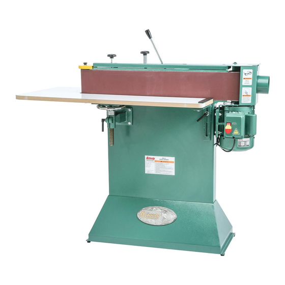
MODEL G0512
6" X 80" EDGE SANDER
w/WRAP-AROUND TABLE
OWNER'S MANUAL
(For models manufactured since 12/22)
COPYRIGHT © MAY, 2003 BY GRIZZLY INDUSTRIAL, INC., REVISED JANUARY, 2023 (CS)
WARNING: NO PORTION OF THIS MANUAL MAY BE REPRODUCED IN ANY SHAPE
OR FORM WITHOUT THE WRITTEN APPROVAL OF GRIZZLY INDUSTRIAL, INC.
#528603624 PRINTED IN TAIWAN
V2.01.23
***Keep for Future Reference***
Advertisement
Table of Contents

Related Manuals for Grizzly G0512


Summary of Contents for Grizzly G0512
- Page 1 OWNER'S MANUAL (For models manufactured since 12/22) COPYRIGHT © MAY, 2003 BY GRIZZLY INDUSTRIAL, INC., REVISED JANUARY, 2023 (CS) WARNING: NO PORTION OF THIS MANUAL MAY BE REPRODUCED IN ANY SHAPE OR FORM WITHOUT THE WRITTEN APPROVAL OF GRIZZLY INDUSTRIAL, INC.
- Page 2 This manual provides critical safety instructions on the proper setup, operation, maintenance, and service of this machine/tool. Save this document, refer to it often, and use it to instruct other operators. Failure to read, understand and follow the instructions in this manual may result in fire or serious personal injury—including amputation, electrocution, or death.
-
Page 3: Table Of Contents
Table of Contents INTRODUCTION ..........2 SECTION 5: ACCESSORIES ......31 Contact Info............ 2 SECTION 6: MAINTENANCE ......33 Manual Accuracy ........... 2 Schedule ............33 Identification ........... 3 Cleaning & Protecting ........33 Controls & Components ......... 4 Cleaning Sanding Belt ......... 33 Machine Data Sheet ........ -
Page 4: Introduction
ID label (see below). This information is required for us to provide proper tech support, and it helps us determine if updated documentation is available for your machine. Manufacture Date Serial Number Model G0512 (Mfd. Since 12/22) -
Page 5: Identification
Manual Before Operating Sander a) Wear eye protection. b) Support workpiece with backstop or worktable. c) Maintain ⁄ " maximum clearance between table and sanding belt. d) Avoid kickback by sanding in accordance with directional arrows. Model G0512 (Mfd. Since 12/22) -
Page 6: Controls & Components
C. ON/OFF Paddle Switch w/Removable Key: injury when operating this machine. Turns motor ON and OFF. Remove yellow key to disable switch. Model G0512 (Mfd. Since 12/22) - Page 7 Belt Tension Lever: Moves away from motor to tension sanding belt; moves toward motor to release sanding belt tension. Figure 4. Location of back stop. Back Stop: Supports workpiece so it does not follow belt travel. Model G0512 (Mfd. Since 12/22)
-
Page 8: Machine Data Sheet
Machine Data Sheet MACHINE DATA SHEET Customer Service #: (570) 546-9663 · To Order Call: (800) 523-4777 · Fax #: (800) 438-5901 MODEL G0512 6" X 80" EDGE SANDER W/ WRAP‐AROUND TABLE Product Dimensions: Weight................................235 lbs. Width (side-to-side) x Depth (front-to-back) x Height............... 52-1/2 x 24 x 48-3/4 in. - Page 9 The information contained herein is deemed accurate as of 1/4/2023 and represents our most recent product specifications. Model G0512 PAGE 2 OF 2 Due to our ongoing improvement efforts, this information may not accurately describe items previously purchased. Model G0512 (Mfd. Since 12/22)
-
Page 10: Section 1: Safety
Never operate under the influence of drugs or injury or blindness from flying particles. Everyday alcohol, when tired, or when distracted. eyeglasses are NOT approved safety glasses. Model G0512 (Mfd. Since 12/22) - Page 11 Make sure they are properly installed, you experience difficulties performing the intend- undamaged, and working correctly BEFORE ed operation, stop using the machine! Contact our operating machine. Technical Support at (570) 546-9663. Model G0512 (Mfd. Since 12/22)
-
Page 12: Additional Safety For Edge Sanders
-10- Model G0512 (Mfd. Since 12/22) -
Page 13: Section 2: Power Supply
To reduce the risk of these hazards, avoid over- loading the machine during operation and make 6-15 PLUG sure it is connected to a power supply circuit that meets the specified circuit requirements. Grounding Pin Figure 6. NEMA 6-15 plug and receptacle. -11- Model G0512 (Mfd. Since 12/22) - Page 14 If you ever notice that a cord or plug is damaged or worn, discon- nect it from power, and immediately replace it with a new one. -12- Model G0512 (Mfd. Since 12/22)
- Page 15 Figure 8. Location of motor junction box cover and screw. Install L5-30 plug on power cord, according to plug manufacturer's instructions. — If plug manufacturer's instructions are not available, NEMA standard L5-30 plug wir- ing provided on Page 45. -13- Model G0512 (Mfd. Since 12/22)
-
Page 16: Section 3: Setup
IMPORTANT: Save all packaging materials until in injury. you are completely satisfied with the machine and have resolved any issues between Grizzly or the shipping agent. You MUST have the original pack- aging to file a freight claim. It is also extremely helpful if you need to return your machine later. -
Page 17: Inventory
K. Table Lock Handles ........3 L. Tap Screws #8 x ⁄ " ......... 19 M. Phillips Head Screws 10-24 x ⁄ " ....4 N. Flat Washers ⁄ " ......... 6 Figure 12. Fasteners. -15- Model G0512 (Mfd. Since 12/22) -
Page 18: Cleanup
Figure 13. T23692 Orange Power Degreaser. Repeat Steps 2–3 as necessary until clean, then coat all unpainted surfaces with a quality metal protectant to prevent rust. -16- Model G0512 (Mfd. Since 12/22) -
Page 19: Site Considerations
Only install in an Shadows, glare, or strobe effects that may distract access restricted location. or impede the operator must be eliminated. Electrical Connection Dust Port 24" Min. 30" 52½" Figure 14. Minimum working clearances. -17- Model G0512 (Mfd. Since 12/22) -
Page 20: Assembly
Figure 15), then stand machine upright. Machine Foot (1 of 4) Figure 17. Installing sanding belt on rollers. Move belt tension lever away from motor to tension belt. Tighten tension/tracking lock knob. Figure 15. Machine foot installed on base. -18- Model G0512 (Mfd. Since 12/22) -
Page 21: Power Connection
Always make sure the ON/OFF switch on the machine is turned OFF before connecting power. NOTICE The Model G0512 is prewired for 220V. If you plan to operate the machine at 110V, Figure 19. Roller guard secured to top of idler the motor must be rewired and an L5-30 roller. -
Page 22: Test Run
Follow Steps 3–5 as described in Pre- working correctly. This safety feature must Tracking Belt on Page 27 to pre-track sand- work properly before proceeding with ing belt. operations. Call Tech Support for help. -20- Model G0512 (Mfd. Since 12/22) -
Page 23: Installing Table
Loosen all (4) table lock handles, use table height handwheel to lower leadscrew table bracket all the way down (see Figure 26), then adjust L-brackets as far down as they will go. Idler Motor L-Bracket L-Bracket Figure 23. L-bracket identification. -21- Model G0512 (Mfd. Since 12/22) - Page 24 13. Remove clamp from leadscrew table bracket. 14. Place square against front center of table and platen (see Figure 27). Platen Figure 29. Using hex wrench as gauge to Square position table. Table Figure 27. Square against table and platen. -22- Model G0512 (Mfd. Since 12/22)
-
Page 25: Dust Collection
⁄ " tap screws. Figure 32. Example of dust hose attached to dust port. Tug hose to make sure it does not come off. Note: A tight fit is necessary for proper per- formance. -23- Model G0512 (Mfd. Since 12/22) -
Page 26: Section 4: Operations
Regardless of the content in this sec- in this manual are easier to understand. tion, Grizzly Industrial will not be held liable for accidents caused by lack of training. Due to the generic nature of this overview, it is not intended to be an instructional guide. -
Page 27: Workpiece Inspection
Always support workpiece against table and back stop when sanding. Use extreme care to provide a safe distance between belt and any body parts. -25- Model G0512 (Mfd. Since 12/22) -
Page 28: Choosing Sanding Belts
Sanding Belts tension (see Figure 33). Belt Tension Tension/ The Model G0512 uses a 6" x 80" sanding belt. Lever Tracking Lock Knob We recommend using aluminum-oxide sand- ing belts for best results. The grit you choose will depend on the condition and species of wood, and the level of finish you wish to achieve. -
Page 29: Pre-Tracking Belt
Gloves could be caught in injured if they touch moving sanding moving parts. surfaces. To reduce this risk, wear gloves while manually pushing belt. Checking/Adjusting Belt Proceed Tracking on Page 28 to complete belt tracking. -27- Model G0512 (Mfd. Since 12/22) -
Page 30: Checking/Adjusting Belt Tracking
Close and latch dust port cover. drive roller, proceed to Step 4. Install roller guard. Drive Roller Sanding Belt Figure 39. Sanding belt even with top of drive roller (dust port removed for clarity). -28- Model G0512 (Mfd. Since 12/22) -
Page 31: Adjusting Table Height
Tighten table lock handles to secure. Support workpiece against back stop and slowly feed workpiece into moving belt with light, even pressure. Maintain control of workpiece, as shown in Figures 42–43. DO NOT force workpiece against belt. -29- Model G0512 (Mfd. Since 12/22) -
Page 32: Contour Sanding
Figure 44, move workpiece profile along roller contour until you achieve desired shape. DO NOT force workpiece against belt. Figure 43. Typical end sanding operation. Figure 44. Typical contour sanding operation. -30- Model G0512 (Mfd. Since 12/22) -
Page 33: Section 5: Accessories
HP Oscillating Spindle Sander These belts feature tough aluminum oxide grain Nothing beats the versatility of this sander when and are sized for the Model G0512. it comes to sanding the edges of contoured or irregularly-shaped workpieces. It features a 14" x 20"... - Page 34 4" dust ports. D4206 D4216 D4256 W1053 W1007 W1317 W1017 Figure 48. G0860 1 ⁄ HP Portable Air Figure 49. Dust collection accessories. Compressor. www.grizzly.com 1-800-523-4777 order online at or call -32- Model G0512 (Mfd. Since 12/22)
-
Page 35: Section 6: Maintenance
Glue used to hold the grit to the belt will rub off onto the Cleaning the Model G0512 is relatively easy. workpiece, causing burns and interference with Vacuum excess wood chips and sawdust, and final finishing. -
Page 36: Lubrication
Table Height Leadscrew Figure 52. T26419 Syn-O-Gen Synthetic Grease. Figure 54. Location of table height leadscrew. -34- Model G0512 (Mfd. Since 12/22) -
Page 37: Section 7: Service
5. Fix/replace fan cover; replace loose/damaged fan. 6. Centrifugal switch needs adjustment/at fault. 6. Adjust/replace if at fault. 7. Motor bearings at fault. 7. Test by rotating shaft; rotational grinding/loose shaft requires bearing replacement. -35- Model G0512 (Mfd. Since 12/22) - Page 38 1. Clean (Page 33) or replace belt (Page 26). Snake-shaped 1. Sanding belt loaded with sawdust, resin, and/ marks on or pitch. workpiece. 2. Replace sanding belt (Page 26). 2. Sanding belt damaged. -36- Model G0512 (Mfd. Since 12/22)
-
Page 39: Adjusting Belt Tensioner
Guard Install sanding belt and examine effect of ten- sion adjustment on belt. Repeat Steps 5–7, if necessary. Figure 56. Location of roller guard and knob. Close dust port cover and install roller guard. -37- Model G0512 (Mfd. Since 12/22) -
Page 40: Resetting Tension Shaft Spring
Note: It may be necessary to slightly adjust tension nut to make table fit. 14. Install and track sanding belt, then close dust Figure 59. Location of roller guard and knob. port cover and install roller guard. -38- Model G0512 (Mfd. Since 12/22) -
Page 41: Checking/Adjusting Parallel Belt Tracking
Wrench 12mm ........... 1 Hex Wrench 3, 8mm ........1 Ea. et should still be attached to table. Level 12" ............1 Remove sanding belt. Loosen (2) cap screws shown in Figure 64 approximately half a turn. -39- Model G0512 (Mfd. Since 12/22) -
Page 42: Platen-To-Roller Adjustments
Straightedge 12" ..........1 11. Install table. Measuring Tape or Calipers ......1 12. Place level on table to check table is level side to side and front to back. Adjust height of L-brackets as necessary. -40- Model G0512 (Mfd. Since 12/22) - Page 43 Figure 69. Checking gap between bottom of platen graphite and drive roller. — If gap between straightedge and drive roller is approximately ⁄ " at top and bot- tom, neither platen nor drive roller need to be adjusted. -41- Model G0512 (Mfd. Since 12/22)
- Page 44 Tighten fasteners from Step 2, being careful 10. Install roller cover and dust port. not to move motor from its corrected position. Repeat Steps 5–6 of Checking Platen-to- Roller Relationships beginning on Page 40. -42- Model G0512 (Mfd. Since 12/22)
- Page 45 Repeat Steps 5–6 of Checking Platen-to- Roller Relationships beginning on Page 40. Repeat Steps 7–8 of Checking Platen-to- Roller Relationships beginning on Page 40. -43- Model G0512 (Mfd. Since 12/22)
-
Page 46: Section 8: Wiring
Technical Support at (570) 546-9663. The photos and diagrams included in this section are best viewed in color. You can view these pages in color at www.grizzly.com. -44- Model G0512 (Mfd. Since 12/22) -
Page 47: Wiring Diagram
6-15 Plug Switch (as recommended) Ground Neutral Ground 110 VAC L5-30 Plug (Rewired for 110V) (as recommended) Figure 73. Motor junction box wiring (220V). Figure 74. Start capacitor wiring. READ ELECTRICAL SAFETY -45- Model G0512 (Mfd. Since 12/22) ON PAGE 44! -
Page 48: Section 9: Parts
SECTION 9: PARTS We do our best to stock replacement parts when possible, but we cannot guarantee that all parts shown are available for purchase. Call (800) 523-4777 or visit www.grizzly.com/parts to check for availability. Main 51AV2 71-1 71-2 71-4... - Page 49 STAR KNOB SMALL P0512050 TAP SCREW #8 X 3/4 P0512115 IDLER ROLLER COVER 51A P0512051A TABLE SUPPORT BRACKET (A) P0512116 FLAT WASHER 1/4 BUY PARTS ONLINE AT GRIZZLY.COM! -47- Model G0512 (Mfd. Since 12/22) Scan QR code to visit our Parts Store.
-
Page 50: Labels & Cosmetics
Safety labels help reduce the risk of serious injury caused by machine hazards. If any label comes off or becomes unreadable, the owner of this machine MUST replace it in the original location before resuming operations. For replacements, contact (800) 523-4777 or www.grizzly.com. BUY PARTS ONLINE AT GRIZZLY.COM! -48- Model G0512 (Mfd. -
Page 51: Warranty & Returns
WARRANTY & RETURNS Grizzly Industrial, Inc. warrants every product it sells for a period of 1 year to the original purchaser from the date of purchase. This warranty does not apply to defects due directly or indirectly to misuse, abuse, negligence, accidents, repairs or alterations or lack of maintenance.
Need help?
Do you have a question about the G0512 and is the answer not in the manual?
Questions and answers